fuse SUBARU TRIBECA 2009 1.G Service Manual Online
[x] Cancel search | Manufacturer: SUBARU, Model Year: 2009, Model line: TRIBECA, Model: SUBARU TRIBECA 2009 1.GPages: 2453, PDF Size: 46.32 MB
Page 2146 of 2453
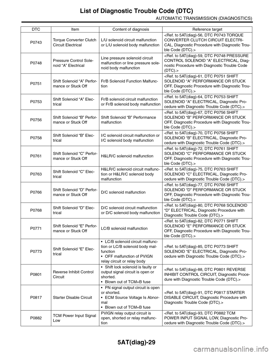
5AT(diag)-29
List of Diagnostic Trouble Code (DTC)
AUTOMATIC TRANSMISSION (DIAGNOSTICS)
P0743To r q u e C o n v e r t e r C l u t c h
Circuit Electrical
L/U solenoid circuit malfunction
or L/U solenoid body malfunction
CAL, Diagnostic Procedure with Diagnostic Trou-
ble Code (DTC).>
P0748Pressure Control Sole-
noid “A” Electrical
Line pressure solenoid circuit
malfunction or line pressure sole-
noid body malfunction
nostic Procedure with Diagnostic Trouble Code
(DTC).>
P0751Shift Solenoid “A” Perfor-
mance or Stuck Off
Fr/B Solenoid Function Malfunc-
tion
OFF, Diagnostic Procedure with Diagnostic Trou-
ble Code (DTC).>
P0753Shift Solenoid “A” Elec-
trical
Fr/B solenoid circuit malfunction
or Fr/B solenoid body malfunction
cedure with Diagnostic Trouble Code (DTC).>
P0756Shift Solenoid “B” Perfor-
mance or Stuck Off
Shift Solenoid “B” Performance
malfunction
OFF, Diagnostic Procedure with Diagnostic Trou-
ble Code (DTC).>
P0758Shift Solenoid “B” Elec-
trical
I/C solenoid circuit malfunction or
I/C solenoid body malfunction
cedure with Diagnostic Trouble Code (DTC).>
P0761Shift Solenoid “C” Perfor-
mance or Stuck OffH&LR/C solenoid malfunction
OFF, Diagnostic Procedure with Diagnostic Trou-
ble Code (DTC).>
P0763Shift Solenoid “C” Elec-
trical
H&LR/C solenoid circuit malfunc-
tion or H&LR/C solenoid body
malfunction
cedure with Diagnostic Trouble Code (DTC).>
P0766Shift Solenoid “D” Perfor-
mance or Stuck OffD/C solenoid malfunction
OFF, Diagnostic Procedure with Diagnostic Trou-
ble Code (DTC).>
P0768Shift Solenoid “D” Elec-
trical
D/C solenoid circuit malfunction
or D/C solenoid body malfunction
Diagnostic Trouble Code (DTC).>
P0771Shift Solenoid “E” Perfor-
mance or Stuck OffLC/B solenoid malfunction
OFF, Diagnostic Procedure with Diagnostic Trou-
ble Code (DTC).>
P0773Shift Solenoid “E” Elec-
trical
•LC/B solenoid circuit malfunc-
tion or LC/B solenoid body mal-
function
•OFF malfunction of PVIGN
relay circuit or relay body
cedure with Diagnostic Trouble Code (DTC).>
P0801Reverse Inhibit Control
Circuit
•Shift lock solenoid is faulty or
output signal circuit is open or
shorted.
•Blown out of TCM+B fuse
dure with Diagnostic Trouble Code (DTC).>
P0817 Starter Disable Circuit
•PN signal output circuit is open
or shorted.
•ECM Source Voltage Is Abnor-
mal
•Blown out of TCM+B fuse
Diagnostic Trouble Code (DTC).>
P0882TCM Power Input Signal
Low
PVIGN relay output circuit is
open, shorted or relay malfunc-
tion
cedure with Diagnostic Trouble Code (DTC).>
DTC Item Content of diagnosis Reference target
Page 2206 of 2453
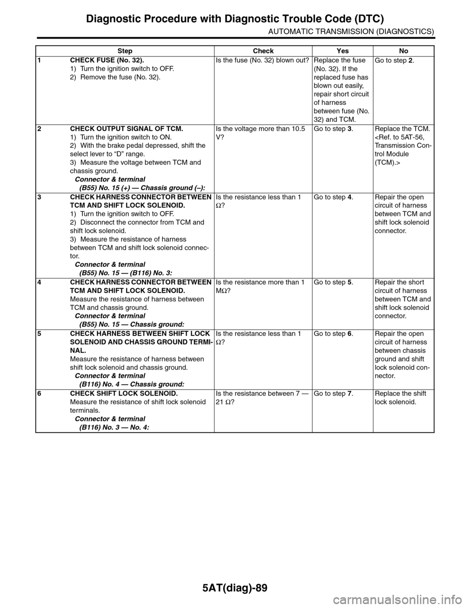
5AT(diag)-89
Diagnostic Procedure with Diagnostic Trouble Code (DTC)
AUTOMATIC TRANSMISSION (DIAGNOSTICS)
Step Check Yes No
1CHECK FUSE (No. 32).
1) Turn the ignition switch to OFF.
2) Remove the fuse (No. 32).
Is the fuse (No. 32) blown out? Replace the fuse
(No. 32). If the
replaced fuse has
blown out easily,
repair short circuit
of harness
between fuse (No.
32) and TCM.
Go to step 2.
2CHECK OUTPUT SIGNAL OF TCM.
1) Turn the ignition switch to ON.
2) With the brake pedal depressed, shift the
select lever to “D” range.
3) Measure the voltage between TCM and
chassis ground.
Connector & terminal
(B55) No. 15 (+) — Chassis ground (–):
Is the voltage more than 10.5
V?
Go to step 3.Replace the TCM.
trol Module
(TCM).>
3CHECK HARNESS CONNECTOR BETWEEN
TCM AND SHIFT LOCK SOLENOID.
1) Turn the ignition switch to OFF.
2) Disconnect the connector from TCM and
shift lock solenoid.
3) Measure the resistance of harness
between TCM and shift lock solenoid connec-
tor.
Connector & terminal
(B55) No. 15 — (B116) No. 3:
Is the resistance less than 1
Ω?
Go to step 4.Repair the open
circuit of harness
between TCM and
shift lock solenoid
connector.
4CHECK HARNESS CONNECTOR BETWEEN
TCM AND SHIFT LOCK SOLENOID.
Measure the resistance of harness between
TCM and chassis ground.
Connector & terminal
(B55) No. 15 — Chassis ground:
Is the resistance more than 1
MΩ?
Go to step 5.Repair the short
circuit of harness
between TCM and
shift lock solenoid
connector.
5CHECK HARNESS BETWEEN SHIFT LOCK
SOLENOID AND CHASSIS GROUND TERMI-
NAL.
Measure the resistance of harness between
shift lock solenoid and chassis ground.
Connector & terminal
(B116) No. 4 — Chassis ground:
Is the resistance less than 1
Ω?
Go to step 6.Repair the open
circuit of harness
between chassis
ground and shift
lock solenoid con-
nector.
6CHECK SHIFT LOCK SOLENOID.
Measure the resistance of shift lock solenoid
terminals.
Connector & terminal
(B116) No. 3 — No. 4:
Is the resistance between 7 —
21 Ω?
Go to step 7.Replace the shift
lock solenoid.
Page 2209 of 2453
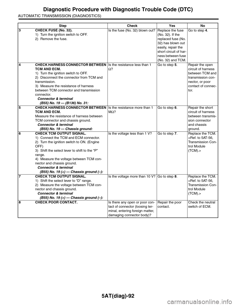
5AT(diag)-92
Diagnostic Procedure with Diagnostic Trouble Code (DTC)
AUTOMATIC TRANSMISSION (DIAGNOSTICS)
3CHECK FUSE (No. 32).
1) Turn the ignition switch to OFF.
2) Remove the fuse.
Is the fuse (No. 32) blown out? Replace the fuse
(No. 32). If the
replaced fuse (No.
32) has blown out
easily, repair the
short circuit of har-
ness between fuse
(No. 32) and TCM.
Go to step 4.
4CHECK HARNESS CONNECTOR BETWEEN
TCM AND ECM.
1) Turn the ignition switch to OFF.
2) Disconnect the connector from TCM and
transmission.
3) Measure the resistance of harness
between TCM connector and transmission
connector.
Connector & terminal
(B55) No. 19 — (B136) No. 31:
Is the resistance less than 1
Ω?
Go to step 5.Repair the open
circuit of harness
between TCM and
transmission con-
nector, or poor
contact of connec-
tor.
5CHECK HARNESS CONNECTOR BETWEEN
TCM AND ECM.
Measure the resistance of harness between
TCM connector and chassis ground.
Connector & terminal
(B55) No. 19 — Chassis ground:
Is the resistance more than 1
MΩ?
Go to step 6.Repair the short
circuit of harness
between transmis-
sion connector
and chassis
ground.
6CHECK TCM OUTPUT SIGNAL.
1) Connect the TCM and ECM connector.
2) Turn the ignition switch to ON. (Engine
OFF)
3) Shift the select lever to shift to the “P”
range.
4) Measure the voltage between TCM con-
nector and chassis ground.
Connector & terminal
(B55) No. 19 (+) — Chassis ground (–):
Is the voltage less than 1 V? Go to step 7.Replace the TCM.
trol Module
(TCM).>
7CHECK TCM OUTPUT SIGNAL.
1) Shift the select lever to “D” range.
2) Measure the voltage between TCM con-
nector and chassis ground.
Connector & terminal
(B55) No. 19 (+) — Chassis ground (–):
Is the voltage more than 10 V? Go to step 8.Replace the TCM.
trol Module
(TCM).>
8CHECK POOR CONTACT.Is there any open or poor con-
tact of connector (loosing ter-
minal, entering foreign matter,
damaging connector body)?
Repair the poor
contact.
Check the neutral
switch of ECM.
Step Check Yes No
Page 2210 of 2453
5AT(diag)-93
Diagnostic Procedure with Diagnostic Trouble Code (DTC)
AUTOMATIC TRANSMISSION (DIAGNOSTICS)
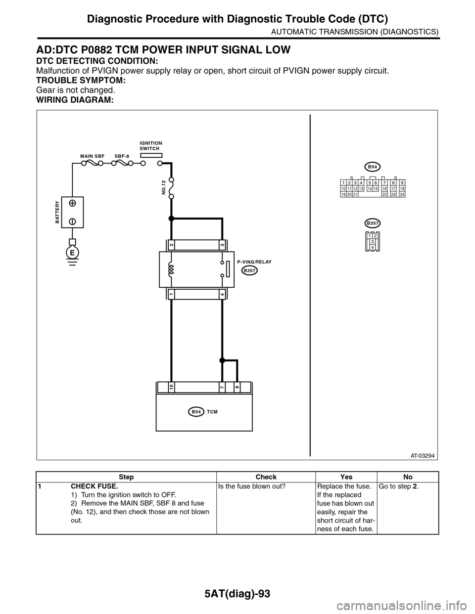
AD:DTC P0882 TCM POWER INPUT SIGNAL LOW
DTC DETECTING CONDITION:
Malfunction of PVIGN power supply relay or open, short circuit of PVIGN power supply circuit.
TROUBLE SYMPTOM:
Gear is not changed.
WIRING DIAGRAM:
AT-03294
8710
B54
B357
TCM
B54
B357
12789563410 11 1219 20 2113 14 15 16 17 18222324
MAIN SBF SBF-8
NO.12
E
32
41
1234
BATTERY
IGNITIONSWITCH
1234
1234
RELAYP-VING
Step Check Yes No
1CHECK FUSE.
1) Turn the ignition switch to OFF.
2) Remove the MAIN SBF, SBF 8 and fuse
(No. 12), and then check those are not blown
out.
Is the fuse blown out? Replace the fuse.
If the replaced
fuse has blown out
easily, repair the
short circuit of har-
ness of each fuse.
Go to step 2.
Page 2211 of 2453
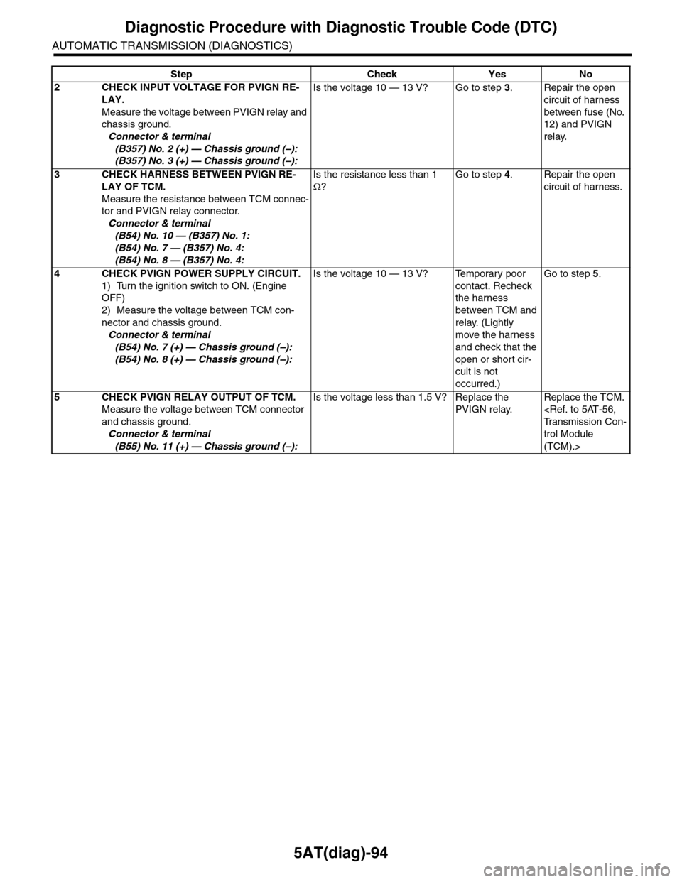
5AT(diag)-94
Diagnostic Procedure with Diagnostic Trouble Code (DTC)
AUTOMATIC TRANSMISSION (DIAGNOSTICS)
2CHECK INPUT VOLTAGE FOR PVIGN RE-
LAY.
Measure the voltage between PVIGN relay and
chassis ground.
Connector & terminal
(B357) No. 2 (+) — Chassis ground (–):
(B357) No. 3 (+) — Chassis ground (–):
Is the voltage 10 — 13 V? Go to step 3.Repair the open
circuit of harness
between fuse (No.
12) and PVIGN
relay.
3CHECK HARNESS BETWEEN PVIGN RE-
LAY OF TCM.
Measure the resistance between TCM connec-
tor and PVIGN relay connector.
Connector & terminal
(B54) No. 10 — (B357) No. 1:
(B54) No. 7 — (B357) No. 4:
(B54) No. 8 — (B357) No. 4:
Is the resistance less than 1
Ω?
Go to step 4.Repair the open
circuit of harness.
4CHECK PVIGN POWER SUPPLY CIRCUIT.
1) Turn the ignition switch to ON. (Engine
OFF)
2) Measure the voltage between TCM con-
nector and chassis ground.
Connector & terminal
(B54) No. 7 (+) — Chassis ground (–):
(B54) No. 8 (+) — Chassis ground (–):
Is the voltage 10 — 13 V? Temporary poor
contact. Recheck
the harness
between TCM and
relay. (Lightly
move the harness
and check that the
open or short cir-
cuit is not
occurred.)
Go to step 5.
5CHECK PVIGN RELAY OUTPUT OF TCM.
Measure the voltage between TCM connector
and chassis ground.
Connector & terminal
(B55) No. 11 (+) — Chassis ground (–):
Is the voltage less than 1.5 V? Replace the
PVIGN relay.
Replace the TCM.
trol Module
(TCM).>
Step Check Yes No
Page 2213 of 2453
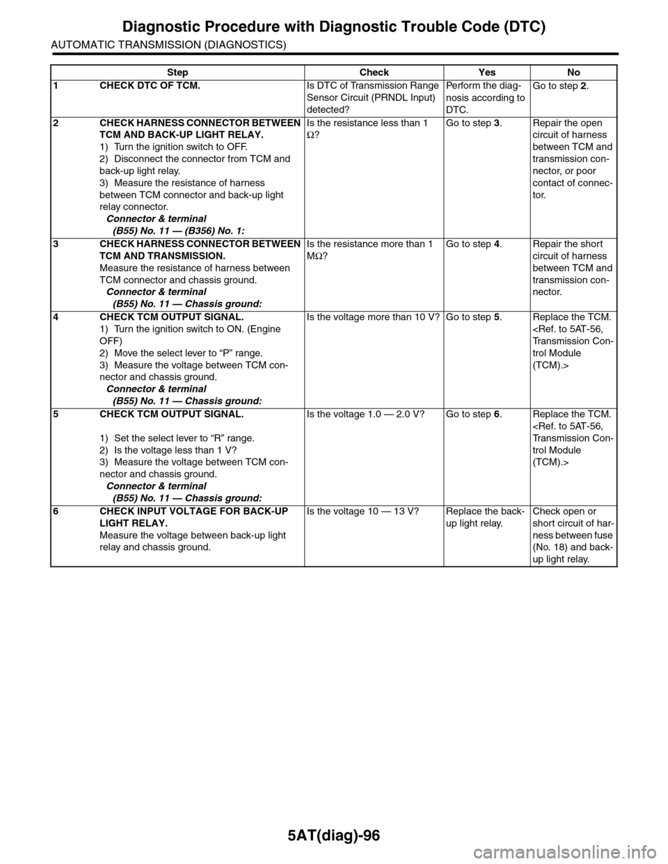
5AT(diag)-96
Diagnostic Procedure with Diagnostic Trouble Code (DTC)
AUTOMATIC TRANSMISSION (DIAGNOSTICS)
Step Check Yes No
1CHECK DTC OF TCM.Is DTC of Transmission Range
Sensor Circuit (PRNDL Input)
detected?
Pe r for m t h e d ia g -
nosis according to
DTC.
Go to step 2.
2CHECK HARNESS CONNECTOR BETWEEN
TCM AND BACK-UP LIGHT RELAY.
1) Turn the ignition switch to OFF.
2) Disconnect the connector from TCM and
back-up light relay.
3) Measure the resistance of harness
between TCM connector and back-up light
relay connector.
Connector & terminal
(B55) No. 11 — (B356) No. 1:
Is the resistance less than 1
Ω?
Go to step 3.Repair the open
circuit of harness
between TCM and
transmission con-
nector, or poor
contact of connec-
tor.
3CHECK HARNESS CONNECTOR BETWEEN
TCM AND TRANSMISSION.
Measure the resistance of harness between
TCM connector and chassis ground.
Connector & terminal
(B55) No. 11 — Chassis ground:
Is the resistance more than 1
MΩ?
Go to step 4.Repair the short
circuit of harness
between TCM and
transmission con-
nector.
4CHECK TCM OUTPUT SIGNAL.
1) Turn the ignition switch to ON. (Engine
OFF)
2) Move the select lever to “P” range.
3) Measure the voltage between TCM con-
nector and chassis ground.
Connector & terminal
(B55) No. 11 — Chassis ground:
Is the voltage more than 10 V? Go to step 5.Replace the TCM.
trol Module
(TCM).>
5CHECK TCM OUTPUT SIGNAL.
1) Set the select lever to “R” range.
2) Is the voltage less than 1 V?
3) Measure the voltage between TCM con-
nector and chassis ground.
Connector & terminal
(B55) No. 11 — Chassis ground:
Is the voltage 1.0 — 2.0 V? Go to step 6.Replace the TCM.
trol Module
(TCM).>
6CHECK INPUT VOLTAGE FOR BACK-UP
LIGHT RELAY.
Measure the voltage between back-up light
relay and chassis ground.
Is the voltage 10 — 13 V? Replace the back-
up light relay.
Check open or
short circuit of har-
ness between fuse
(No. 18) and back-
up light relay.
Page 2215 of 2453
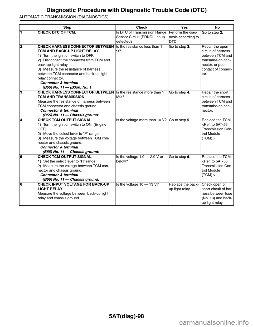
5AT(diag)-98
Diagnostic Procedure with Diagnostic Trouble Code (DTC)
AUTOMATIC TRANSMISSION (DIAGNOSTICS)
Step Check Yes No
1CHECK DTC OF TCM.Is DTC of Transmission Range
Sensor Circuit (PRNDL Input)
detected?
Pe r for m t h e d ia g -
nosis according to
DTC.
Go to step 2.
2CHECK HARNESS CONNECTOR BETWEEN
TCM AND BACK-UP LIGHT RELAY.
1) Turn the ignition switch to OFF.
2) Disconnect the connector from TCM and
back-up light relay.
3) Measure the resistance of harness
between TCM connector and back-up light
relay connector.
Connector & terminal
(B55) No. 11 — (B356) No. 1:
Is the resistance less than 1
Ω?
Go to step 3.Repair the open
circuit of harness
between TCM and
transmission con-
nector, or poor
contact of connec-
tor.
3CHECK HARNESS CONNECTOR BETWEEN
TCM AND TRANSMISSION.
Measure the resistance of harness between
TCM connector and chassis ground.
Connector & terminal
(B55) No. 11 — Chassis ground:
Is the resistance more than 1
MΩ?
Go to step 4.Repair the short
circuit of harness
between TCM and
transmission con-
nector.
4CHECK TCM OUTPUT SIGNAL.
1) Turn the ignition switch to ON. (Engine
OFF)
2) Move the select lever to “P” range.
3) Measure the voltage between TCM con-
nector and chassis ground.
Connector & terminal
(B55) No. 11 — Chassis ground:
Is the voltage more than 10 V? Go to step 5.Replace the TCM.
trol Module
(TCM).>
5CHECK TCM OUTPUT SIGNAL.
1) Set the select lever to “R” range.
2) Measure the voltage between TCM con-
nector and chassis ground.
Connector & terminal
(B55) No. 11 — Chassis ground:
Is the voltage 1.0 — 2.0 V or
below?
Go to step 6.Replace the TCM.
trol Module
(TCM).>
6CHECK INPUT VOLTAGE FOR BACK-UP
LIGHT RELAY.
Measure the voltage between back-up light
relay and chassis ground.
Is the voltage 10 — 13 V? Replace the back-
up light relay.
Check open or
short circuit of har-
ness between fuse
(No. 18) and back-
up light relay.
Page 2264 of 2453
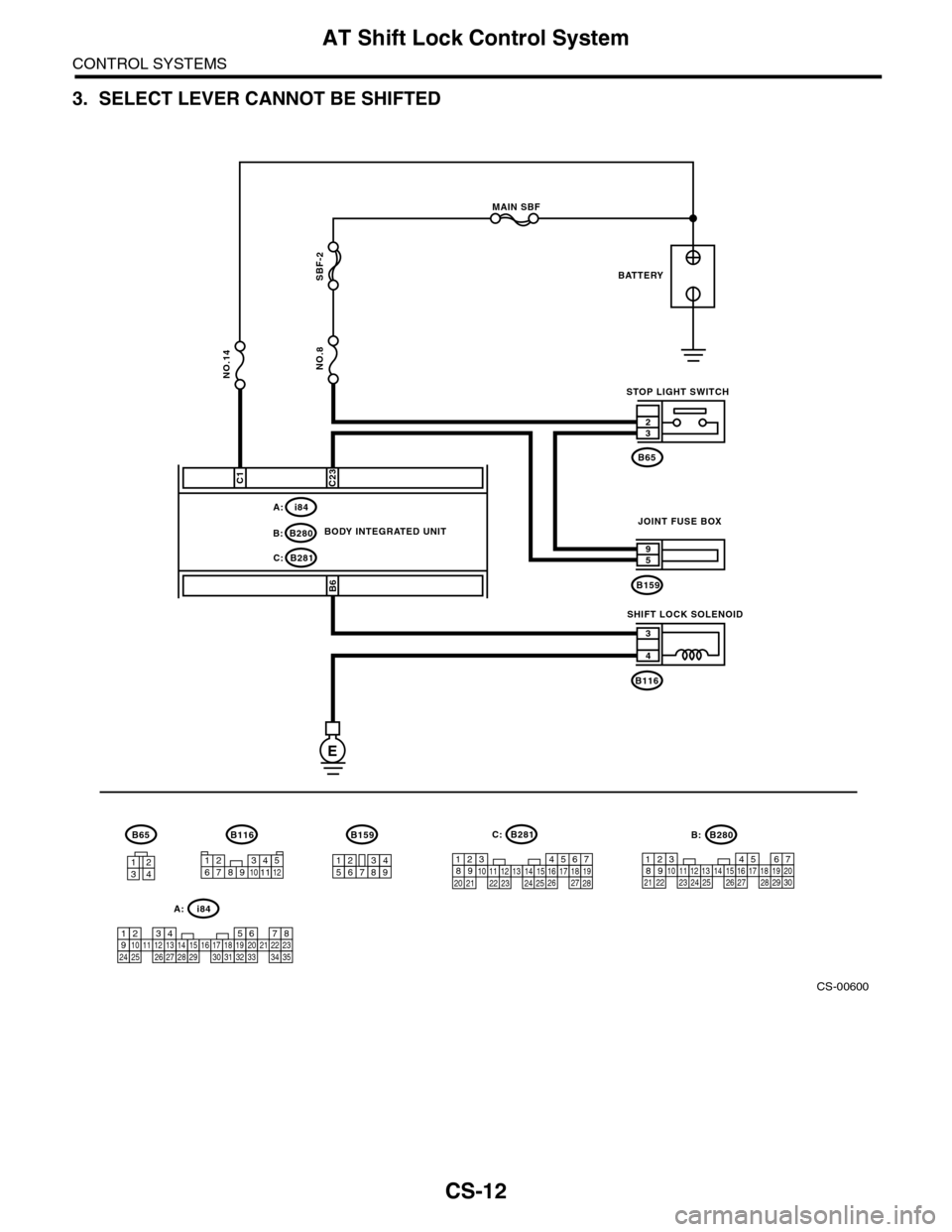
CS-12
AT Shift Lock Control System
CONTROL SYSTEMS
3. SELECT LEVER CANNOT BE SHIFTED
CS-00600
B281C:
i84A:
MAIN SBF
SBF-2
NO.8
E
B281C:
i84A:
C23
B6B159
59
B116
4
3
32
B65
BATTERY
STOP LIGHT SWITCH
BODY INTEGRATED UNITJOINT FUSE BOX
SHIFT LOCK SOLENOID
B116
1234
B65
567821943102422 23 25111213141526 27281617181920 21
1234567891011121314151617181920212223242526272829303132333435
123456789
B159
C1
NO.14
1234567891011125467821931022 231112131415242526 2716171828 29192021 30
B280B:
B280B:
Page 2266 of 2453
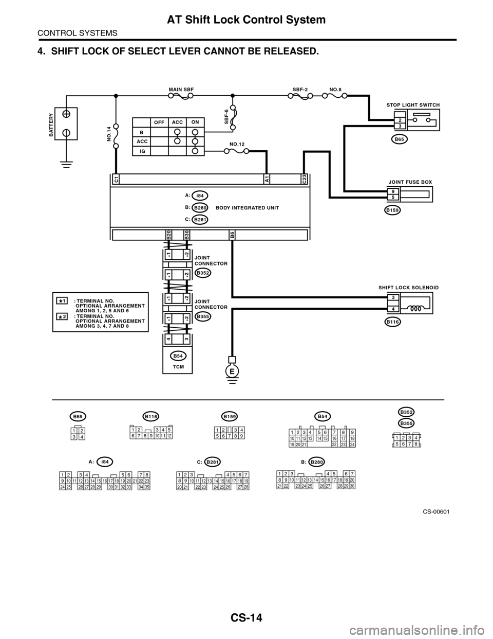
CS-14
AT Shift Lock Control System
CONTROL SYSTEMS
4. SHIFT LOCK OF SELECT LEVER CANNOT BE RELEASED.
CS-00601
NO.8
E
B280B:
B281C:
C23C1
B6
B
ACC
IG
ACCOFFON
A1
NO.12
SBF-2MAIN SBF
SBF-6
B159
59
B116
4
3
B65
B30B20
B116
1234
B65B159
123456789
567821943102422 23 25111213141526 27281617181920 21
B281
5467821931022 231112131415242526 2716171828 29192021 30
B280i84
1234567891011121314151617181920212223242526272829303132333435
i84A:
12789563410 11 1219 20 2113 14 15 16 17 18222324
B54
NO.14
A:C: B:
BODY INTEGRATED UNIT
STOP LIGHT SWITCH
SHIFT LOCK SOLENOID
JOINT FUSE BOX
32
TCM
B54
B355
B352
34561278
*1*2
*1*2
*1*2
*1*2
43
B352
JOINTCONNECTOR
B355
JOINTCONNECTOR
BATTERY
1
*
: TERMINAL NO. OPTIONAL ARRANGEMENT AMONG 1, 2, 5 AND 6: TERMINAL NO. OPTIONAL ARRANGEMENT AMONG 3, 4, 7 AND 8
123456789101112
*
2
Page 2287 of 2453
WI-3
Basic Diagnostic Procedure
WIRING SYSTEM
1. Basic Diagnostic Procedure
A: BASIC PROCEDURES
1. GENERAL DESCRIPTION
The most important purpose of diagnostics is to
quickly determine which part is malfunctioning, to
save time and labor.
2. IDENTIFICATION OF TROUBLE SYMP-
TOM
Determine what the problem is based on the symp-
tom.
3. PROBABLE CAUSE OF TROUBLE
Look at the wiring diagram and check the system’s
circuit. Then check the switch, relay, fuse, ground,
etc.
4. LOCATION AND REPAIR OF TROUBLE
1) Using the diagnostics, narrow down the causes.
2) If necessary, use a voltmeter, ohmmeter, etc.
3) Before replacing certain component parts
(switch, relay, etc.), check the power supply,
ground, for open wiring harness, poor connectors,
etc. If no problem is encountered, check the com-
ponent parts.
5. SYSTEM OPERATION CHECK
After repairing, ensure that the system operates
properly.
B: BASIC INSPECTION
1. VOLTAGE MEASUREMENT
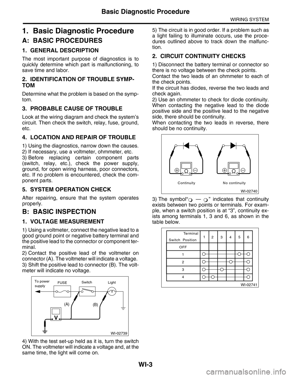
1) Using a voltmeter, connect the negative lead to a
good ground point or negative battery terminal and
the positive lead to the connector or component ter-
minal.
2) Contact the positive lead of the voltmeter on
connector (A). The voltmeter will indicate a voltage.
3) Shift the positive lead to connector (B). The volt-
meter will indicate no voltage.
4) With the test set-up held as it is, turn the switch
ON. The voltmeter will indicate a voltage and, at the
same time, the light will come on.
5) The circuit is in good order. If a problem such as
a light failing to illuminate occurs, use the proce-
dures outlined above to track down the malfunc-
tion.
2. CIRCUIT CONTINUITY CHECKS
1) Disconnect the battery terminal or connector so
there is no voltage between the check points.
Contact the two leads of an ohmmeter to each of
the check points.
If the circuit has diodes, reverse the two leads and
check again.
2) Use an ohmmeter to check for diode continuity.
When contacting the negative lead to the diode
positive side and the positive lead to the negative
side, there should be continuity.
When contacting the two leads in reverse, there
should be no continuity.
3) The symbol“ — ” indicates that continuity
exists between two points or terminals. For exam-
ple, when a switch position is at “3”, continuity ex-
ists among terminals 1, 3 and 6, as shown in the
table below.
WI-02739
To powerFUSEsupplySwitchLight
V
(A)(B)
WI-02740
Continuity No continuity
�