SUZUKI GRAND VITARA 1987 Service Repair Manual
Manufacturer: SUZUKI, Model Year: 1987, Model line: GRAND VITARA, Model: SUZUKI GRAND VITARA 1987Pages: 962, PDF Size: 27.87 MB
Page 461 of 962
![SUZUKI GRAND VITARA 1987 Service Repair Manual INSPECTION21-8. OIL PRESSURE LAMP
[Brake fluid level switch]
Use ohmmeter to check switch for resistance
and continuity.
If found defective, replace switch.
The oil pressure lamp circuit consists of t SUZUKI GRAND VITARA 1987 Service Repair Manual INSPECTION21-8. OIL PRESSURE LAMP
[Brake fluid level switch]
Use ohmmeter to check switch for resistance
and continuity.
If found defective, replace switch.
The oil pressure lamp circuit consists of t](/img/20/57437/w960_57437-460.png)
INSPECTION21-8. OIL PRESSURE LAMP
[Brake fluid level switch]
Use ohmmeter to check switch for resistance
and continuity.
If found defective, replace switch.
The oil pressure lamp circuit consists of the oil
pressure switch installed to the cylinder block
and the lamp (warning lamp) inside the combi-
nation meter.
The oil pressure switch so operates that it is
switched OFF when oil pressure is produced by
the started engine and then fed to switch.
Fig. 21-23W/R : White/Red
6 : Black
RI0 : RedlBlack
1. Battery
2. Main switch
3. Fuse4. Oil pressure lamp
6. Oil pressure switch
B/El : Black/Blue
B/W : Black/White
Y/0 : Yellow/Black
W/Y : White/Yellow
Fig. 21-24
INSPECTION
[Oil pressure switch]
Use a ohmmeter to check the switch continuity.
During engine
Running
No continuity
obtained (- 52 1
IAt Engine StopContinuity obtained
(052)
1. To wiring harness
2. Cylinder block
Fig. 21-2521-14
Page 462 of 962
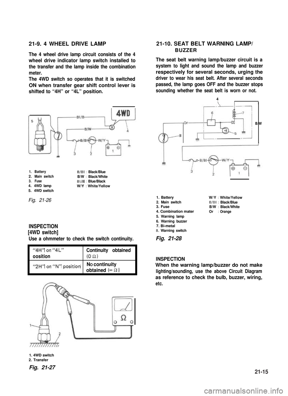
21-9. 4 WHEEL DRIVE LAMP21-10. SEAT BELT WARNING LAMP/
BUZZERThe 4 wheel drive lamp circuit consists of the 4
wheel drive indicator lamp switch installed to
the transfer and the lamp inside the combination
meter.
The 4WD switch so operates that it is switched
ON when transfer gear shift control lever is
shifted to “4H” or “4L” position.
The seat belt warning lamp/buzzer circuit is a
system to light and sound the lamp and buzzer
respectively for several seconds, urging the
driver to wear his seat belt. After several seconds
passed, the lamp goes OFF and the buzzer stops
sounding whether the seat belt is worn or not.
1.BatteryB/B1:Black/Blue2.Main switchB/W:Black/White3.FuseBI/B:Blue/Black4.4WD lampW/Y:White/Yellow5.4WD switch
Fig. 21-26
INSPECTION
[4WD switch]
Use a ohmmeter to check the switch continuity.
I
“4H” or “4L”Continuity obtained
oosition(052)I
I
#,2HM or ##N## positionNO continuity
obtained (- 52 1I
CL-
01
8
4\II
B/W
1. Battery
2. Main switch3. Fuse
4. Combination mater
5. Warning lamp
6. Warning buzzer7. Bi-metal8. Warning switch
W/Y:White/Yellow
BIBI:Black/BlueB/W:Black/White
Or:Orange
Fig. 21-28
INSPECTION
When the warning lamp/buzzer do not make
lighting/sounding, use the above Circuit Diagram
as reference to check the bulb, buzzer, wiring,
etc.
1. 4WD switch
2. Transfer
Fig. 21-2721-15
Page 463 of 962
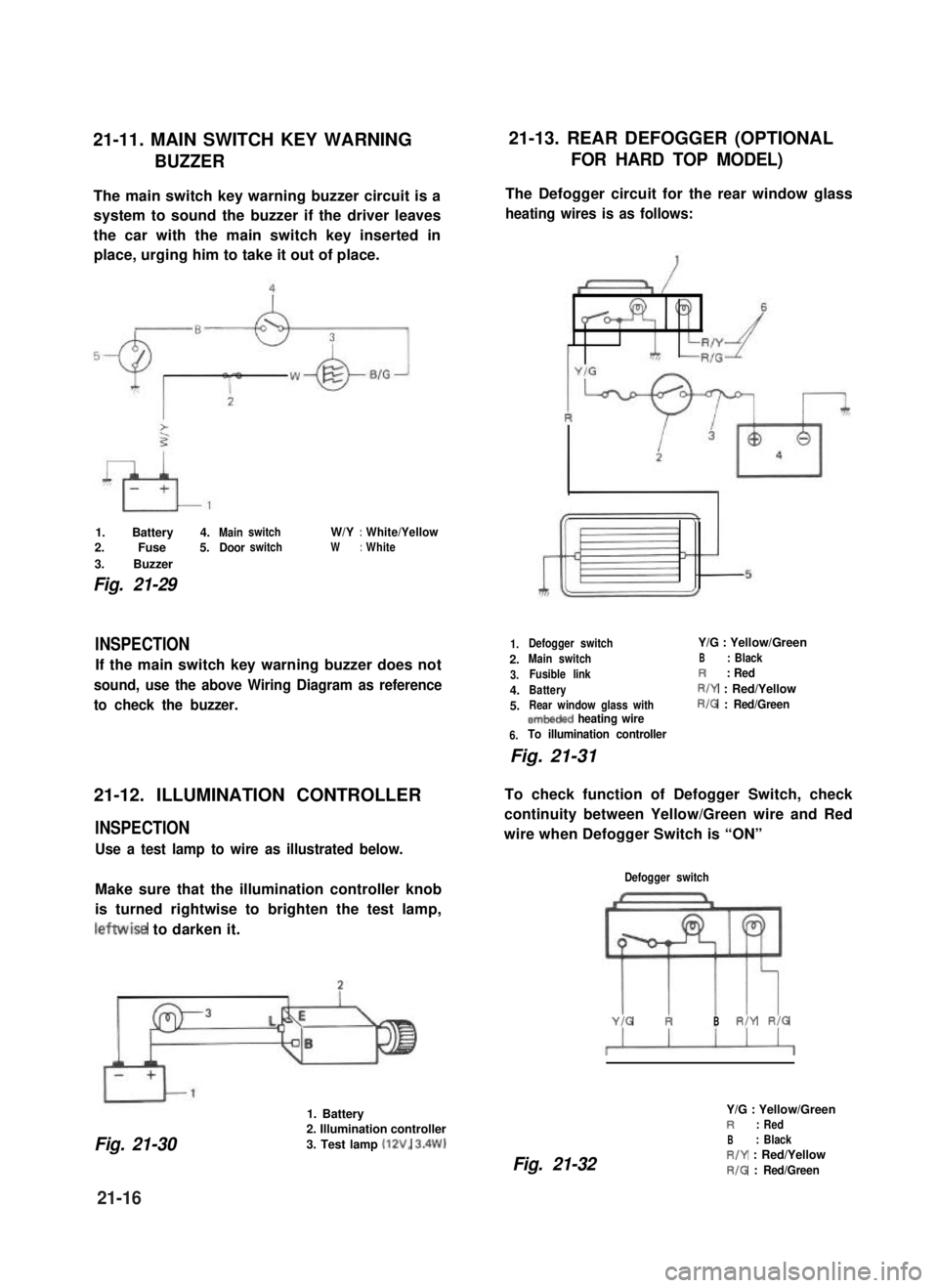
21-11. MAIN SWITCH KEY WARNING21-13. REAR DEFOGGER (OPTIONAL
BUZZERFOR HARD TOP MODEL)
The main switch key warning buzzer circuit is a
system to sound the buzzer if the driver leaves
the car with the main switch key inserted in
place, urging him to take it out of place.
1. Battery 4.MainswitchW/Y:White/Yellow
2. Fuse 5.DoorswitchW:White
3. Buzzer
Fig. 21-29
INSPECTION
If the main switch key warning buzzer does not
sound, use the above Wiring Diagram as reference
to check the buzzer.
21-12. ILLUMINATION CONTROLLER
INSPECTION
Use a test lamp to wire as illustrated below.
Make sure that the illumination controller knob
is turned rightwise to brighten the test lamp,
leftwise to darken it.
1. Battery
Fig. 21-30
2. Illumination controller
3. Test lamp (12V, 3.4W)
The Defogger circuit for the rear window glass
heating wires is as follows:
1.
2.
3.
4.
5.
6.
Defogger switchY/G : Yellow/Green
Main switchB: Black
Fusible linkR: Red
BatteryR/Y : Red/Yellow
Rear window glass withR/G : Red/Greenembeded heating wire
To illumination controller
Fig. 21-31
To check function of Defogger Switch, check
continuity between Yellow/Green wire and Red
wire when Defogger Switch is “ON”
Defogger switch
YIG RBR/Y RIG
Fig. 21-32
Y/G : Yellow/GreenR: Red
B: BlackR/Y : Red/Yellow
R/G : Red/Green
21-16
Page 464 of 962
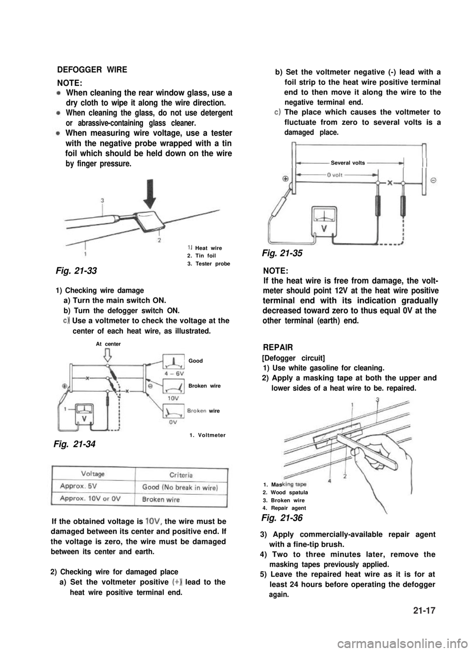
DEFOGGER WIRE
NOTE:
When cleaning the rear window glass, use a
dry cloth to wipe it along the wire direction.
When cleaning the glass, do not use detergent
or abrassive-containing glass cleaner.
When measuring wire voltage, use a tester
with the negative probe wrapped with a tin
foil which should be held down on the wire
by finger pressure.
1. Heat wire2. Tin foil
3. Tester probe
Fig. 21-33 NOTE:
1) Checking wire damage
a) Turn the main switch ON.
b) Turn the defogger switch ON.
c) Use a voltmeter to check the voltage at the
center of each heat wire, as illustrated.
At center
Good
Broken wire
B.roken wire
1. Voltmeter
Fig. 21-34
If the obtained voltage is lOV, the wire must be
damaged between its center and positive end. If
the voltage is zero, the wire must be damaged
between its center and earth.
2) Checking wire for damaged place
a) Set the voltmeter positive (+) lead to the
heat wire positive terminal end.
b) Set the voltmeter negative (-) lead with a
foil strip to the heat wire positive terminal
end to then move it along the wire to the
negative terminal end.
c) The place which causes the voltmeter to
fluctuate from zero to several volts is a
damaged place.
Several volts -_(( (
Fig. 21-35
If the heat wire is free from damage, the volt-
meter should point 12V at the heat wire positive
terminal end with its indication gradually
decreased toward zero to thus equal 0V at the
other terminal (earth) end.
REPAIR
[Defogger circuit]
1) Use white gasoline for cleaning.
2) Apply a masking tape at both the upper and
lower sides of a heat wire to be. repaired.
1. Mas
2. Wood spatula
3. Broken wire4. Repair agent
Fig. 21-36
3) Apply commercially-available repair agent
with a fine-tip brush.
4) Two to three minutes later, remove the
masking tapes previously applied.
5) Leave the repaired heat wire as it is for at
least 24 hours before operating the defogger
again.
21-17
Page 465 of 962
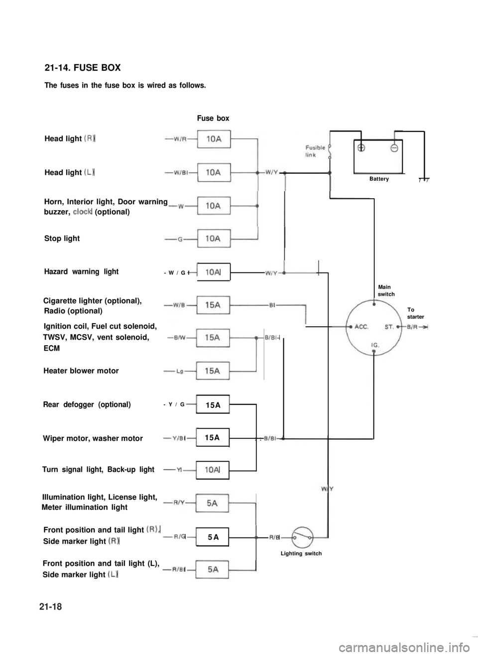
21-14. FUSE BOX
The fuses in the fuse box is wired as follows.
Head light (R)
Fuse box
Head light (L)Battery7
Horn, Interior light, Door warning
buzzer, ctock (optional)
Stop light
Hazard warning light-W/GI10AW,YI
Cigarette lighter (optional),
Radio (optional)
-w’B++-B7Ignition coil, Fuel cut solenoid,
TWSV, MCSV, vent solenoid,-B/W15A
3
BIBI-
ECM
Heater blower motor-L9
Rear defogger (optional)-Y/G15A
Wiper motor, washer motor-Y/El15A:: BIBI-
Turn signal light, Back-up light-Y10A
Illumination light, License light,
Meter illumination light
-R’y++lFront position and tail light (RI,
Side marker light (RI--RIG5A:: RIB
Lighting switch
Front position and tail light (L), --R,a,
Side marker light (L)
-t
-c
Mainswitch
Tostarter
B/R--,
-
21-18
Page 466 of 962
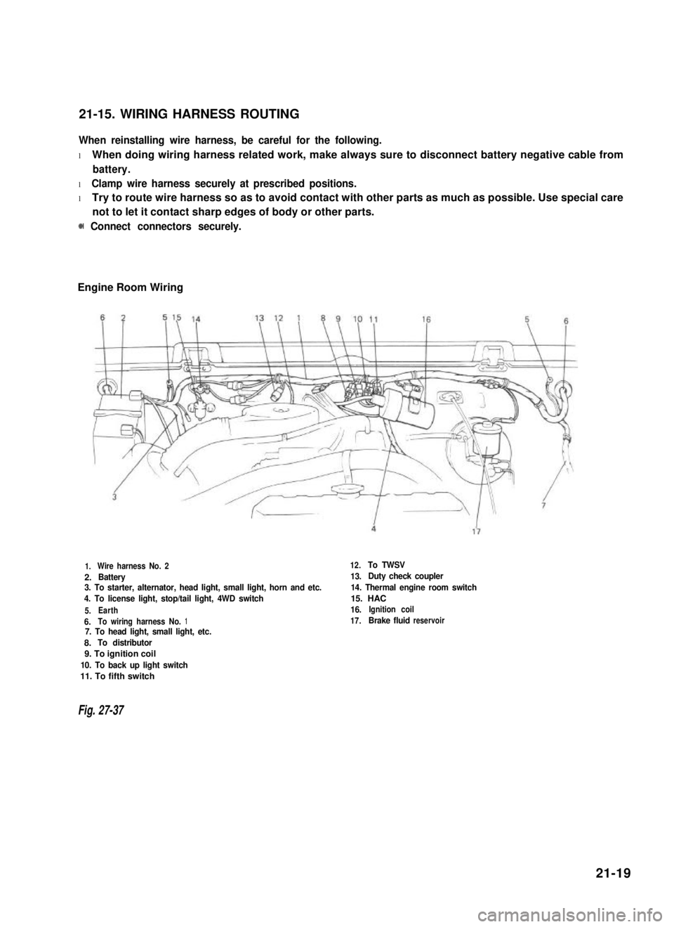
21-15. WIRING HARNESS ROUTING
When reinstalling wire harness, be careful for the following.
l When doing wiring harness related work, make always sure to disconnect battery negative cable from
battery.
l Clamp wire harness securely at prescribed positions.
l Try to route wire harness so as to avoid contact with other parts as much as possible. Use special care
not to let it contact sharp edges of body or other parts.
0 Connect connectors securely.
Engine Room Wiring
1.Wire harness No. 2
2.Battery3. To starter, alternator, head light, small light, horn and etc.
4. To license light, stop/tail light, 4WD switch
5.Earth
6.To wiring harness No.17. To head light, small light, etc.
8.To distributor
9. To ignition coil
10. To back up light switch
11. To fifth switch
12.To TWSV
13.Duty check coupler
14. Thermal engine room switch
15. HAC
16.Ignition coil
17.Brake fluidreservoir
Fig. 27-37
21-19
Page 467 of 962
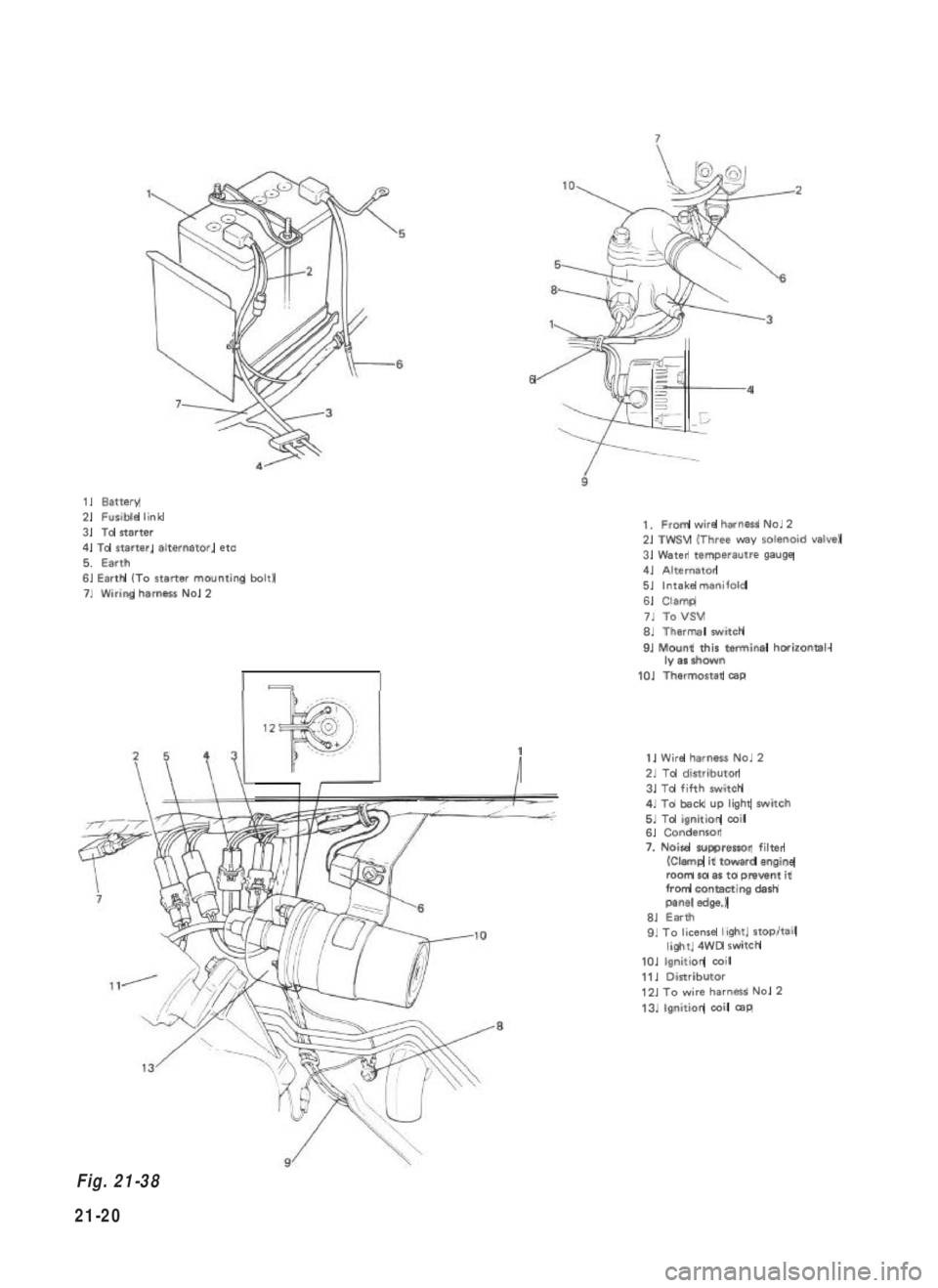
1.Battery2.Fusible link
3.To starter
4. To starter, alternator, etc
5.Earth6. Earth (To starter mounting bolt)7.Wiring harnessNo.2
64
1
I
1.From wire harnessNo.22. TWSV (Three way solenoid valve)
3. Water temperautre gauge4.Alternator5.Intake manifold
6.Clamp
7.ToVSV6.Thermal switch
9. Mount this terminal horizontal-ly as shown
10.Thermostat cap
1. Wire harness No. 2
2. To distributor
3. To fifth switch4. To back up light switch5. To ignition coil6. Condensor
7. Noise suppressor filter(Clamp it toward engineroom so as to prevent itfrom contacting dashpanel edge.)6. Earth9. To license light, stop/taillight, 4WD switch
10. Ignition coil
11. Distributor12. To wire harness No. 2
13. Ignition coil cap
Fig. 21-38
21-20
Page 468 of 962
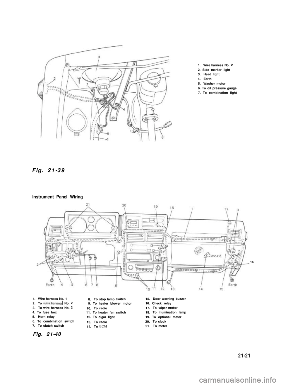
Fig. 21-39
Instrument Panel Wiring
1.Wire harness No.2
2. Side marker light3.Head light
4.Earth
5.Washer motor
6. To oil pressure gauge
7. To combination light
16
1.Wire harness No. 1
2.To wire~harness No.2
3.To wire harness No.2
4. To fuse box5.Horn relay
6. To combination switch7.To clutch switch
8.Tostop lampswitch15.Doorwarning buzzer
9. To heater blower motor16. Check relay
10.Toradio17.To wipermotor
Il. To heater fan switch18.To illumination lamp
12. To cigar light19. To optional meter
13.Toradio20.Toclock
14.ToECM21.Tometer
Fig. 21-40
21-21
Page 469 of 962
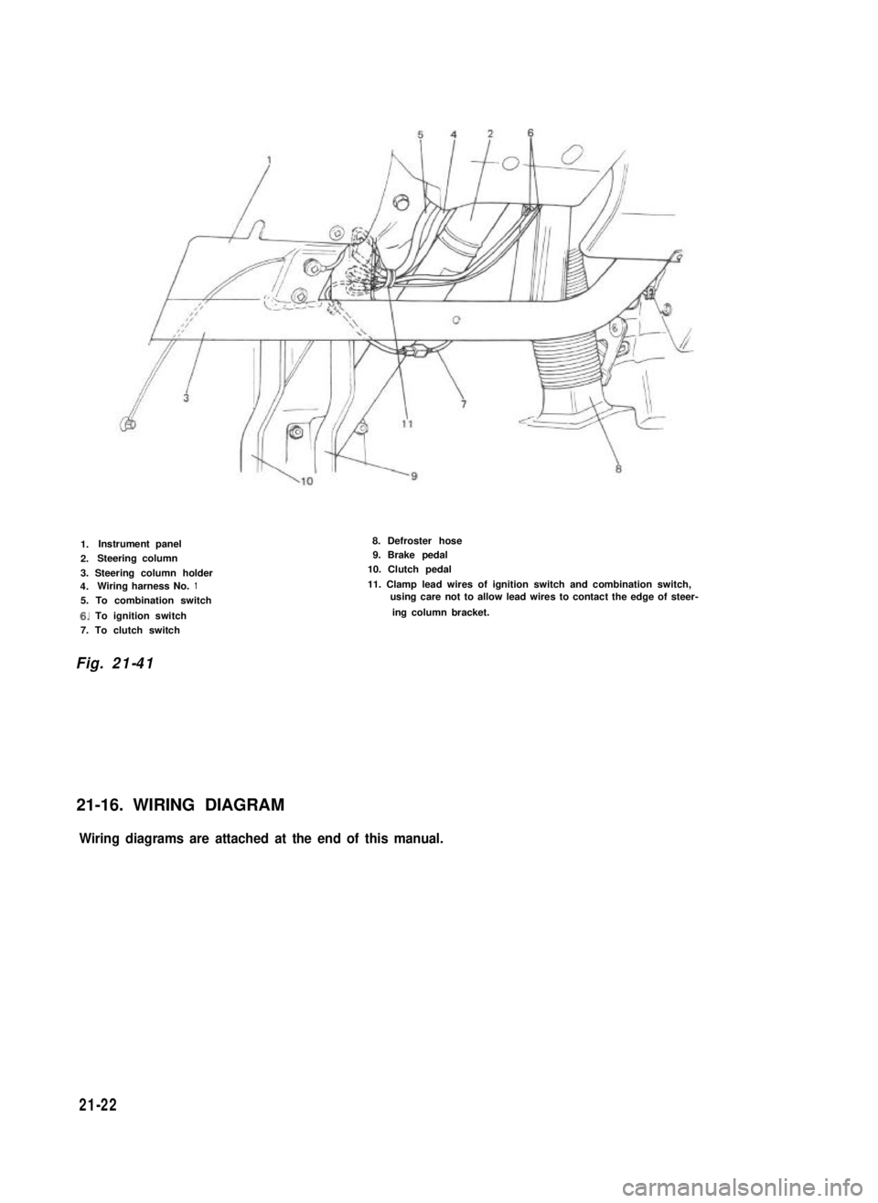
1.Instrument panel
2.Steering column
3. Steering column holder4.Wiring harness No.1
5. To combination switch
6. To ignition switch
7. To clutch switch
8. Defroster hose9. Brake pedal
10. Clutch pedal
11. Clamp lead wires of ignition switch and combination switch,using care not to allow lead wires to contact the edge of steer-
ing column bracket.
Fig. 21-41
21-16. WIRING DIAGRAM
Wiring diagrams are attached at the end of this manual.
21-22
Page 470 of 962
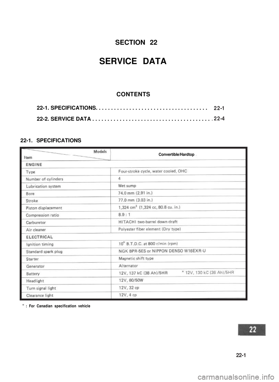
SECTION 22
SERVICE DATA
CONTENTS
22-1. SPECIFICATIONS. . . . . . . . . . . . . . . . . . . . . . . . . . . . . . . . . . . . .
22-2. SERVICE DATA . . . . . . . . . . . . . . . . . . . . . . . . . . . . . . . . . . . . . . .
22-1. SPECIFICATIONS
Convertible/Hardtop
* : For Canadian specification vehicle
22-1
22-4
22-1