SUZUKI GRAND VITARA 1987 Service Repair Manual
Manufacturer: SUZUKI, Model Year: 1987, Model line: GRAND VITARA, Model: SUZUKI GRAND VITARA 1987Pages: 962, PDF Size: 27.87 MB
Page 421 of 962
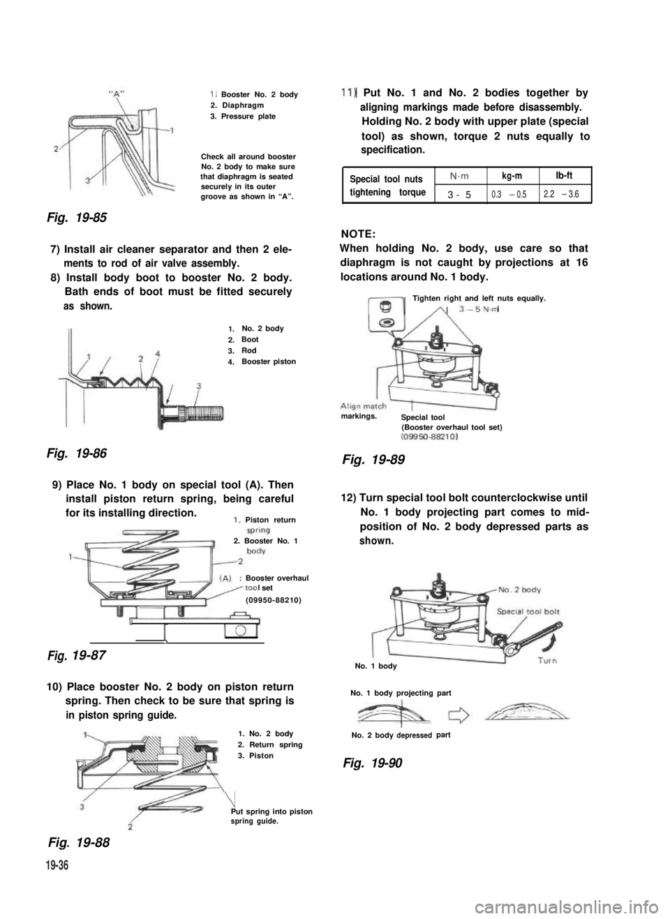
2,
Fig. 19-85
1. Booster No. 2 body2. Diaphragm
3. Pressure plate
Check all around boosterNo. 2 body to make surethat diaphragm is seatedsecurely in its outergroove as shown in “A”.
7) Install air cleaner separator and then 2 ele-
ments to rod of air valve assembly.
8) Install body boot to booster No. 2 body.
Bath ends of boot must be fitted securely
as shown.
Fig. 19-86
1.No. 2 body
2.Boot
3.Rod
4.Booster piston
9) Place No. 1 body on special tool (A). Then
install piston return spring, being careful
for its installing direction.1. Piston return
Fig.
2. Booster No. 1
:Booster overhaultool set
(09950-88210)
1
I
19-87
10) Place booster No. 2 body on piston return
spring. Then check to be sure that spring is
in piston spring guide.
Fig.. 19-88
1. No. 2 body
2. Return spring
3. Piston
\Put spring into pistonspring guide.
11) Put No. 1 and No. 2 bodies together by
aligning markings made before disassembly.
Holding No. 2 body with upper plate (special
tool) as shown, torque 2 nuts equally to
specification.
Special tool nutsN.mkg-mlb-ft
tightening torque3-50.3 - 0.52.2 - 3.6
NOTE:
When holding No. 2 body, use care so that
diaphragm is not caught by projections at 16
locations around No. 1 body.
ml
Tighten right and left nuts equally.
A 3-5N.m
markings.Special tool(Booster overhaul tool set)(08850-88210)
Fig. 19-89
12) Turn special tool bolt counterclockwise until
No. 1 body projecting part comes to mid-
position of No. 2 body depressed parts as
shown.
No. 1 body
No. 1 body projecting part
No. 2 bodydepressedpart
Fig. 19-90
19-36
Page 422 of 962
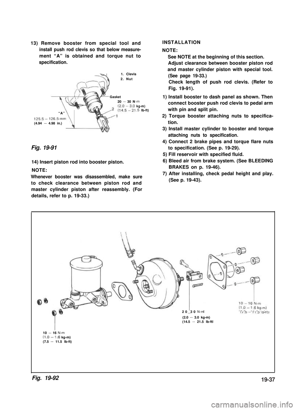
13) Remove booster from special tool and
install push rod clevis so that below measure-
ment “A” is obtained and torque nut to
specification.
-41. Clevis
2. Nut
Gasket20 - 30 N
“A”
125.5- 126.5mm(4.94 - 4.98 in.)\
.rnkg-m).5 lb-ft)
Fig. 19-91
14) Insert piston rod into booster piston.
NOTE:
Whenever booster was disassembled, make sure
to check clearance between piston rod and
INSTALLATION
NOTE:
See NOTE at the beginning of this section.
Adjust clearance between booster piston rod
and master cylinder piston with special tool.
(See page 19-33.)
Check length of push rod clevis. (Refer to
Fig. 19-91).
1) Install booster to dash panel as shown. Then
connect booster push rod clevis to pedal arm
with pin and split pin.
2) Torque booster attaching nuts to specifica-
tion.
3) Install master cylinder to booster and torque
attaching nuts to specification.
4) Connect 2 brake pipes and torque flare nuts
to specification. (See p. 19-29).
5) Fill reservoir with specified fluid.
6) Bleed air from brake system. (See BLEEDING
BRAKES on p. 19-46).
7) After installing, check pedal height and play.
(See p. 19-43).
master cylinder piston after reassembly. (For
details, refer to p. 19-33.)
20 30 N.m-(2.0 - 3.0 kg-m)(14.5 - 21.5 lb-ftl
10 - 16 N.m(1.0-1.6 kg-m)(7.5 - 11.5 lb-ft)
Fig. 19-9219-37
Page 423 of 962
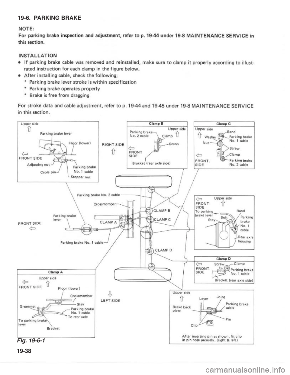
Fig. 19-6-1
19-38
19-6. PARKING BRAKE
Page 424 of 962
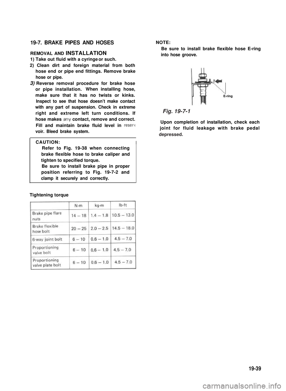
19-7. BRAKE PIPES AND HOSES
REMOVAL AND INSTALLATION
1) Take out fluid with a cyringe or such.
2) Clean dirt and foreign material from both
hose end or pipe end fittings. Remove brake
hose or pipe.
3) Reverse removal procedure for brake hose
or pipe installation.When installing hose,
make sure that it has no twists or kinks.
Inspect to see that hose doesn’t make contact
with any part of suspension. Check in extreme
right and extreme left turn conditions. If
hose makes .any contact, remove and correct.
Fill and maintain brake fluid level in reser-
voir. Bleed brake system.
NOTE:
Be sure to install brake flexible hose E-ring
into hose groove.
z+
\E-ring
Upon completion of installation, check each
joint for fluid leakage with brake pedal
CAUTION:I
Refer to Fig. 19-38 when connecting
brake flexible hose to brake caliper and
tighten to specified torque.
Be sure to install brake pipe in proper
position referring to Fig. 19-7-2 and
clamp it securely and correctly.
Tightening torque
19-39
Fig. 19-7-1
depressed.
Page 425 of 962
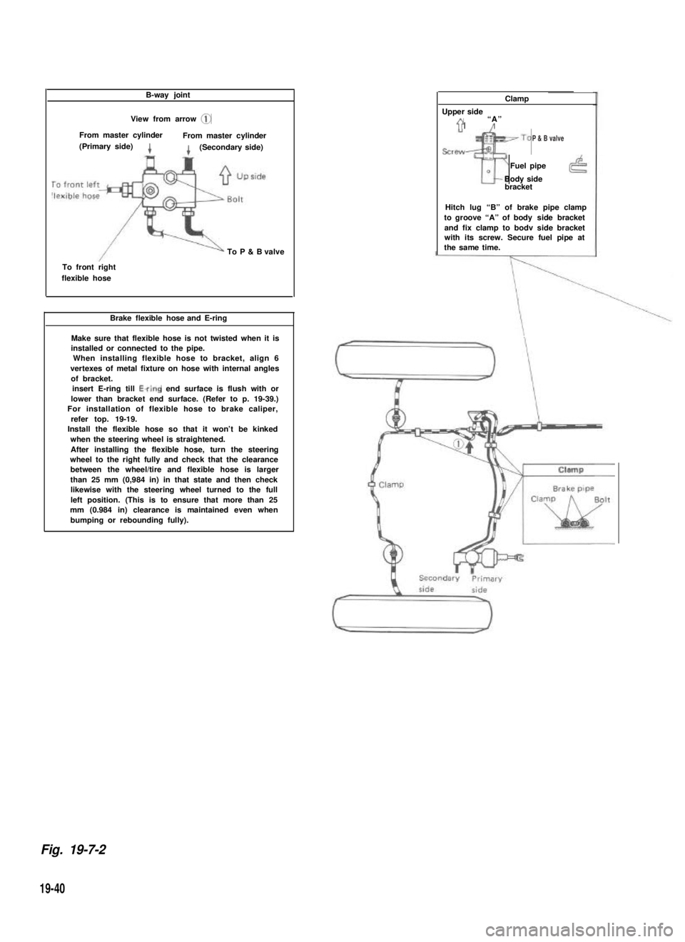
B-way joint
View from arrow @
From master cylinderFrom master cylinder(Primary side)4(Secondary side)
To P & B valve
To front rightflexible hose
Brake flexible hose and E-ring
Make sure that flexible hose is not twisted when it isinstalled or connected to the pipe.When installing flexible hose to bracket, align 6vertexes of metal fixture on hose with internal anglesof bracket.insert E-ring till Ewing end surface is flush with orlower than bracket end surface. (Refer to p. 19-39.) For installation of flexible hose to brake caliper,refer top. 19-19. Install the flexible hose so that it won’t be kinkedwhen the steering wheel is straightened.After installing the flexible hose, turn the steeringwheel to the right fully and check that the clearancebetween the wheel/tire and flexible hose is largerthan 25 mm (0,984 in) in that state and then checklikewise with the steering wheel turned to the fullleft position. (This is to ensure that more than 25mm (0.984 in) clearance is maintained even whenbumping or rebounding fully).
Clamp
Upper sideA“A”71’/
sre~~To
Tr
Fuel pipe0Body sidebracket
Hitch lug “B” of brake pipe clampto groove “A” of body side bracketand fix clamp to bodv side bracketwith its screw. Secure fuel pipe atthe same time.
Fig. 19-7-2
19-40
P & B valve
Page 426 of 962
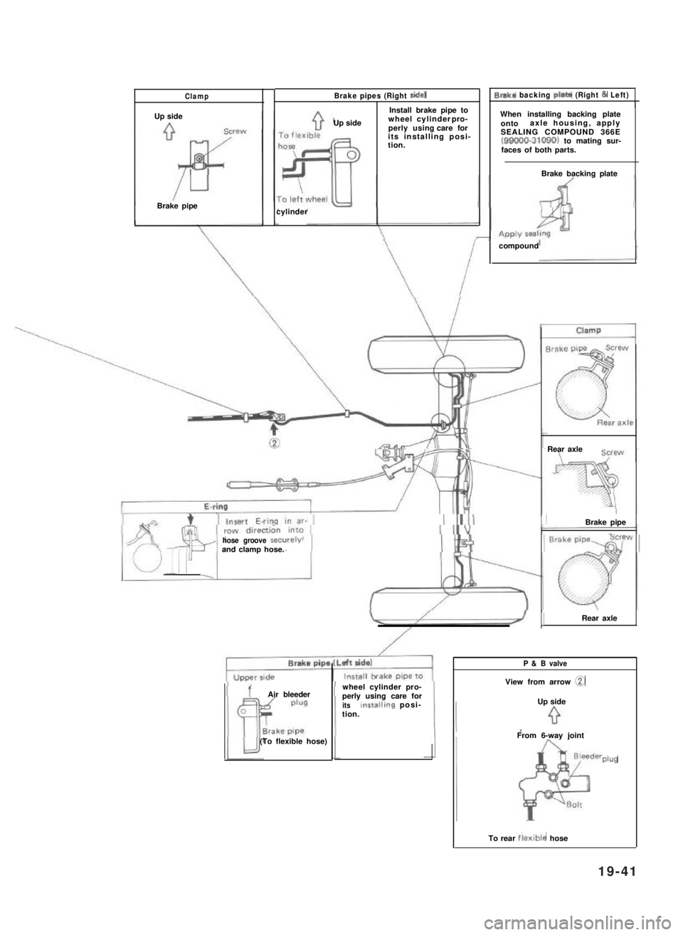
Clamp
Up side
Brake pipe
Brake pipes (Right side)
Install brake pipe to
Up sidewheel cylinder pro-perly using care forits installing posi-tion.
cylinder
Blake backing Plato (Right & Left)
When installing backing plateontoaxle housing, applySEALING COMPOUND 366E(99000-31090) to mating sur-faces of both parts.
Brake backing plate
compound
hose groove securelyand clamp hose.
Air bleeder
(To flexible hose)
wheel cylinder pro-perly using care foritsinstallrng posi-tion.
Rear axle
IBrake pipe
1Rear axle
P & B valve
View from arrow @
Up side
From 6-way joint
Plug
To rear flexible hose
19-41
Page 427 of 962
19-8. MAINTENANCE SERVICE
ROAD TESTING BRAKES
Brakes should be tested on dry, clean, smooth
and reasonably level roadway which is not
crowned. Road test brakes by making brake
applications with both light and heavy pedal
forces at various speeds to determine if the car
stops evenly and effectively.
Also drive car to see if it leads to one side or the
other without brake application. If it does,
check tire pressure, front end alignment and
front suspension attachments for looseness.
See diagnosis chart for other causes.
BRAKE FLUID LEAKS
Check master cylinder fluid levels. While a slight
drop in reservoir level does result from normal
lining wear, an abnormally low level indicates a
leak in the system.In such a case, check the
entire brake system for leakage. If even a slight
evidence of leakage is noted, the cause should be
corrected or defective parts should be replaced.
BRAKE FLUID LEVEL INSPECTION
Be sure to use particular brake fluid either as
marked on reservoir cap of that car or recom-
mended in owner’s manual which comes along
with that car.
Use of any other fluid is strictly prohibited.
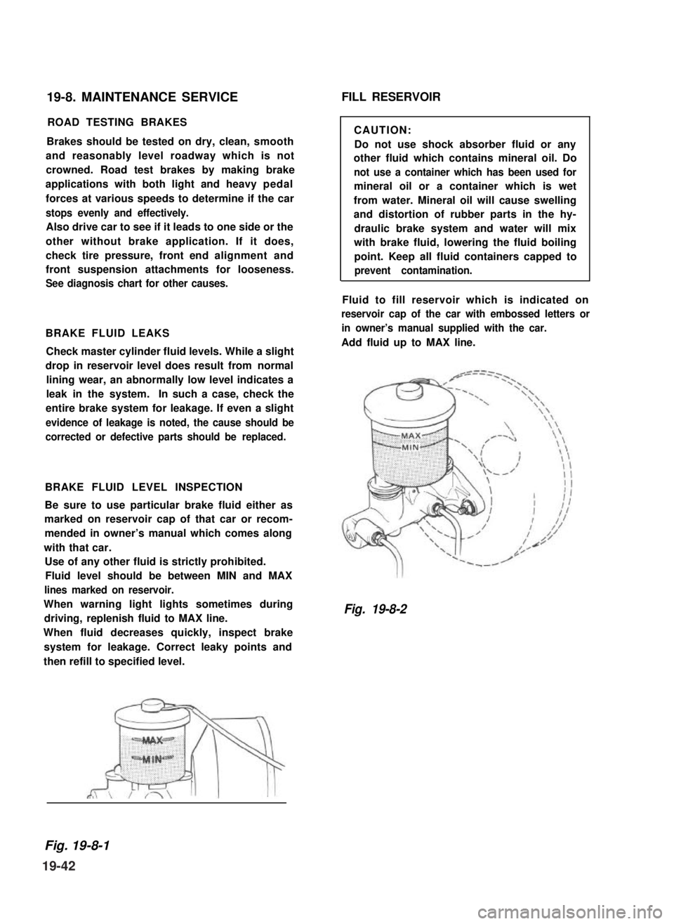
Fluid level should be between MIN and MAX
lines marked on reservoir.
When warning light lights sometimes during
driving, replenish fluid to MAX line.
When fluid decreases quickly, inspect brake
system for leakage. Correct leaky points and
then refill to specified level.
FILL RESERVOIR
CAUTION:
Do not use shock absorber fluid or any
other fluid which contains mineral oil. Do
not use a container which has been used for
mineral oil or a container which is wet
from water. Mineral oil will cause swelling
and distortion of rubber parts in the hy-
draulic brake system and water will mix
with brake fluid, lowering the fluid boiling
point. Keep all fluid containers capped to
prevent contamination.
Fluid to fill reservoir which is indicated on
reservoir cap of the car with embossed letters or
in owner’s manual supplied with the car.
Add fluid up to MAX line.
Fig. 19-8-2
Fig. 19-8-1
19-42
Page 428 of 962
BRAKE PEDAL FREE HEIGHT ADJUSTMENT
Brake pedal height is normal if brake pedal is
as high as clutch pedal.
1) When booster push rod clevis has been
reinstalled, it is important that measurement
between booster mounting surface (with a
gasket attached) and the center of clevis
pin hole is adjusted within 125.5 mm -
126.5 mm (4.94 - 4.98 in.). (See page
19-37.)
2) When stop light switch has been removed,
refer to the following STOP LIGHT SWITCH
ADJUSTMENT for proper installation.
The services in above steps 1) and 2) may
affect brake pedal height.
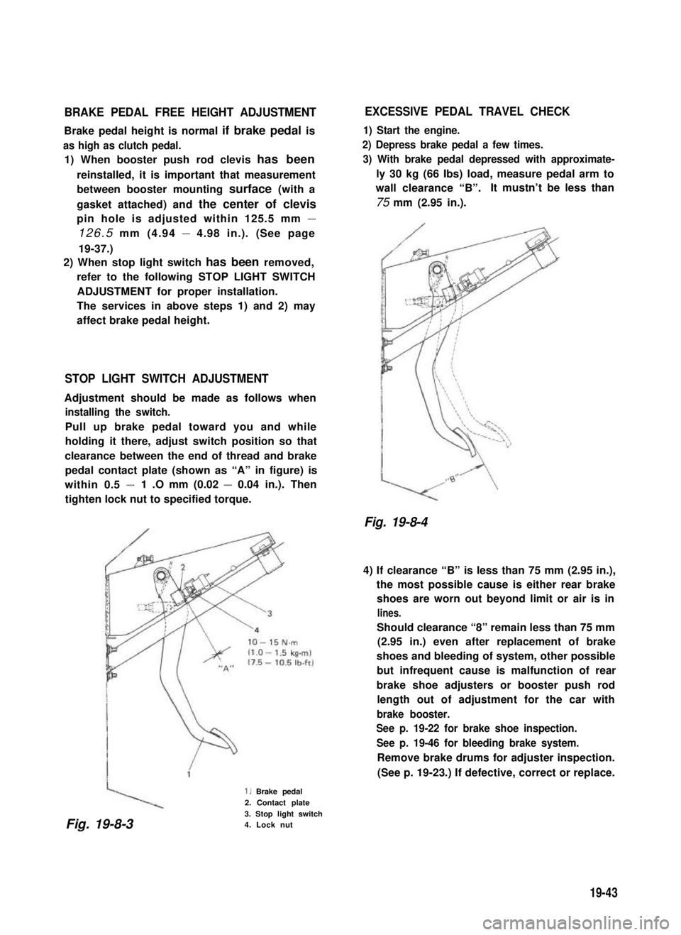
STOP LIGHT SWITCH ADJUSTMENT
Adjustment should be made as follows when
installing the switch.
Pull up brake pedal toward you and while
holding it there, adjust switch position so that
clearance between the end of thread and brake
pedal contact plate (shown as “A” in figure) is
within 0.5 -1 .O mm (0.02 - 0.04 in.). Then
tighten lock nut to specified torque.
1. Brake pedal
2. Contact plate
3. Stop light switch4. Lock nut
EXCESSIVE PEDAL TRAVEL CHECK
1) Start the engine.
2) Depress brake pedal a few times.
3) With brake pedal depressed with approximate-
ly 30 kg (66 Ibs) load, measure pedal arm to
wall clearance “B”.It mustn’t be less than
75 mm (2.95 in.).
Fig. 19-8-4
4) If clearance “B” is less than 75 mm (2.95 in.),
the most possible cause is either rear brake
shoes are worn out beyond limit or air is in
lines.
Should clearance “8” remain less than 75 mm
(2.95 in.) even after replacement of brake
shoes and bleeding of system, other possible
but infrequent cause is malfunction of rear
brake shoe adjusters or booster push rod
length out of adjustment for the car with
brake booster.
See p. 19-22 for brake shoe inspection.
See p. 19-46 for bleeding brake system.
Remove brake drums for adjuster inspection.
(See p. 19-23.) If defective, correct or replace.
Fig. 19-8-3
19-43
Page 429 of 962
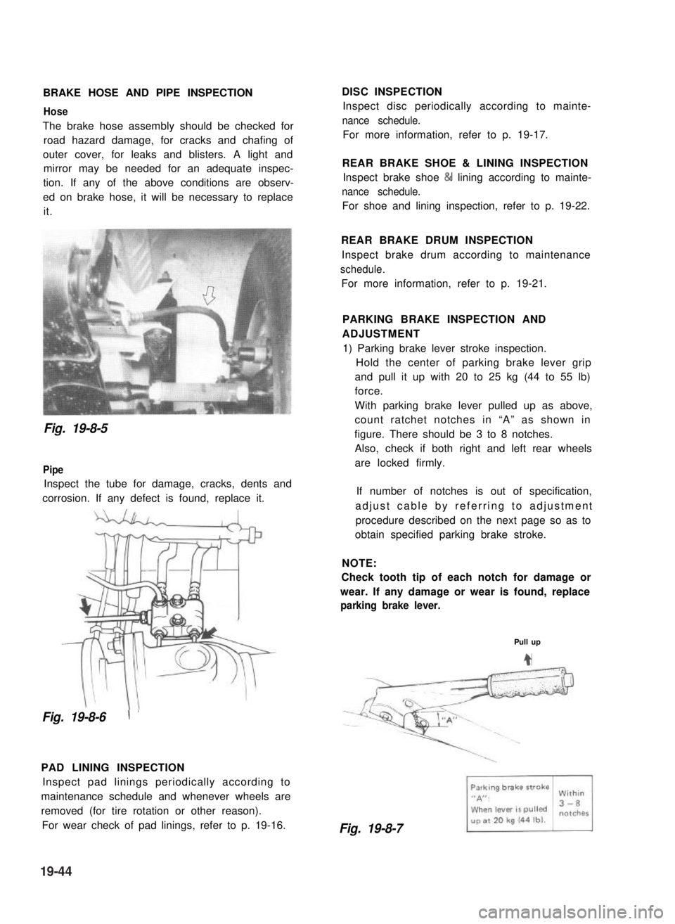
BRAKE HOSE AND PIPE INSPECTION
Hose
The brake hose assembly should be checked for
road hazard damage, for cracks and chafing of
outer cover, for leaks and blisters. A light and
mirror may be needed for an adequate inspec-
tion. If any of the above conditions are observ-
ed on brake hose, it will be necessary to replace
it.
DISC INSPECTION
Inspect disc periodically according to mainte-
nance schedule.
For more information, refer to p. 19-17.
REAR BRAKE SHOE & LINING INSPECTION
Inspect brake shoe & lining according to mainte-
nance schedule.
For shoe and lining inspection, refer to p. 19-22.
Fig. 19-8-5
Pipe
Inspect the tube for damage, cracks, dents and
corrosion. If any defect is found, replace it.
Fig. 19-8-6\ ’
PAD LINING INSPECTION
Inspect pad linings periodically according to
maintenance schedule and whenever wheels are
removed (for tire rotation or other reason).
For wear check of pad linings, refer to p. 19-16.
REAR BRAKE DRUM INSPECTION
Inspect brake drum according to maintenance
schedule.
For more information, refer to p. 19-21.
PARKING BRAKE INSPECTION AND
ADJUSTMENT
1) Parking brake lever stroke inspection.
Hold the center of parking brake lever grip
and pull it up with 20 to 25 kg (44 to 55 lb)
force.
With parking brake lever pulled up as above,
count ratchet notches in “A” as shown in
figure. There should be 3 to 8 notches.
Also, check if both right and left rear wheels
are locked firmly.
If number of notches is out of specification,
adjust cable by referring to adjustment
procedure described on the next page so as to
obtain specified parking brake stroke.
NOTE:
Check tooth tip of each notch for damage or
wear. If any damage or wear is found, replace
parking brake lever.
Pull up
4
Fig. 19-8-7
19-44
Page 430 of 962
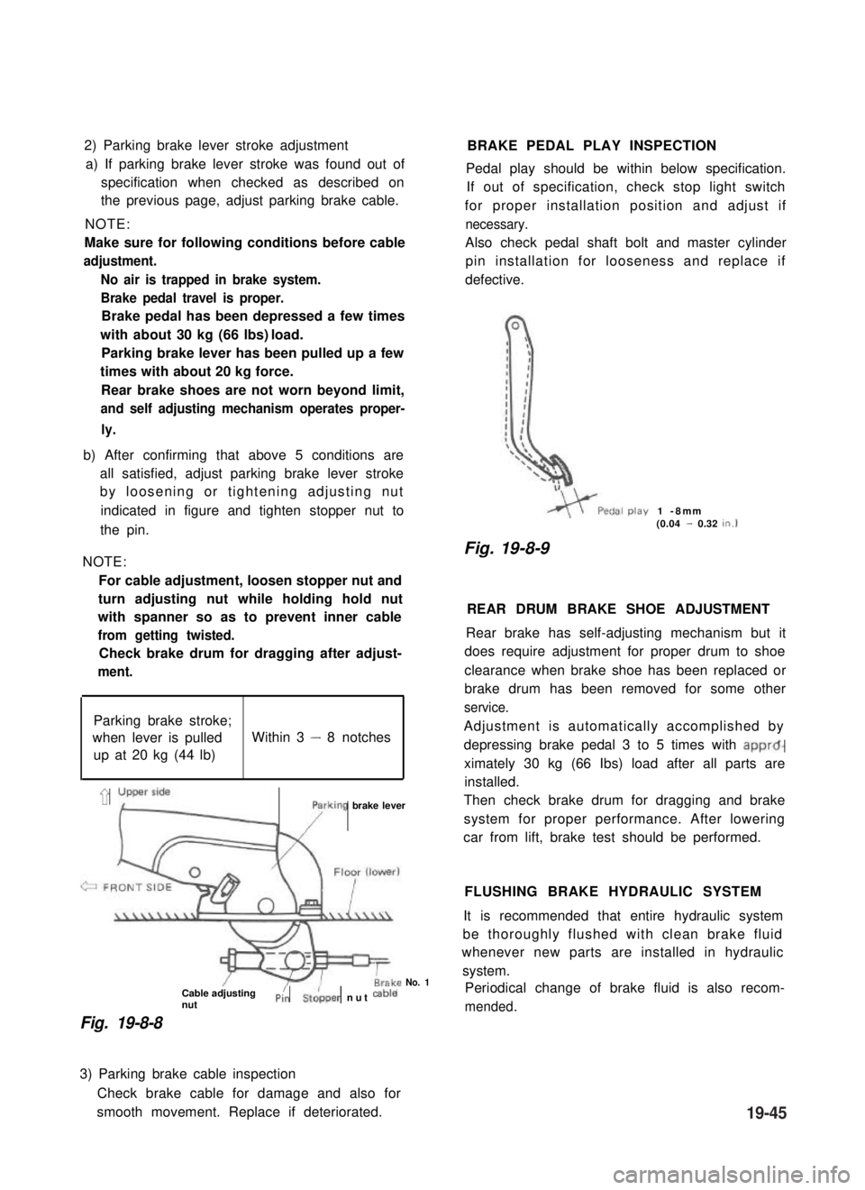
2) Parking brake lever stroke adjustment
a) If parking brake lever stroke was found out of
specification when checked as described on
the previous page, adjust parking brake cable.
NOTE:
Make sure for following conditions before cable
adjustment.
No air is trapped in brake system.
Brake pedal travel is proper.
Brake pedal has been depressed a few times
with about 30 kg (66 lbs) load.
Parking brake lever has been pulled up a few
times with about 20 kg force.
Rear brake shoes are not worn beyond limit,
and self adjusting mechanism operates proper-
ly.
b) After confirming that above 5 conditions are
all satisfied, adjust parking brake lever stroke
by loosening or tightening adjusting nut
indicated in figure and tighten stopper nut to
the pin.
NOTE:
For cable adjustment, loosen stopper nut and
turn adjusting nut while holding hold nut
with spanner so as to prevent inner cable
from getting twisted.
Check brake drum for dragging after adjust-
ment.
Parking brake stroke;
when lever is pulledWithin 3 - 8 notches
up at 20 kg (44 lb)
’ yLyFrking brake lever
Cable adjustingnutPi:St&per nut cab’e
Fig. 19-8-8
No. 1
BRAKE PEDAL PLAY INSPECTION
Pedal play should be within below specification.
If out of specification, check stop light switch
for proper installation position and adjust if
necessary.
Also check pedal shaft bolt and master cylinder
pin installation for looseness and replace if
defective.
play1 -8mm(0.04 - 0.32tn.1
Fig. 19-8-9
REAR DRUM BRAKE SHOE ADJUSTMENT
Rear brake has self-adjusting mechanism but it
does require adjustment for proper drum to shoe
clearance when brake shoe has been replaced or
brake drum has been removed for some other
service.
Adjustment is automatically accomplished by
depressing brake pedal 3 to 5 times with apprd-
ximately 30 kg (66 Ibs) load after all parts are
installed.
Then check brake drum for dragging and brake
system for proper performance. After lowering
car from lift, brake test should be performed.
FLUSHING BRAKE HYDRAULIC SYSTEM
It is recommended that entire hydraulic system
be thoroughly flushed with clean brake fluid
whenever new parts are installed in hydraulic
system.
Periodical change of brake fluid is also recom-
mended.
3) Parking brake cable inspection
Check brake cable for damage and also for
smooth movement. Replace if deteriorated.19-45