SUZUKI JIMNY 2005 3.G Service Workshop Manual
Manufacturer: SUZUKI, Model Year: 2005, Model line: JIMNY, Model: SUZUKI JIMNY 2005 3.GPages: 687, PDF Size: 13.38 MB
Page 101 of 687
Downloaded from www.Manualslib.com manuals search engine 1B-40 AIR CONDITIONING (OPTIONAL)
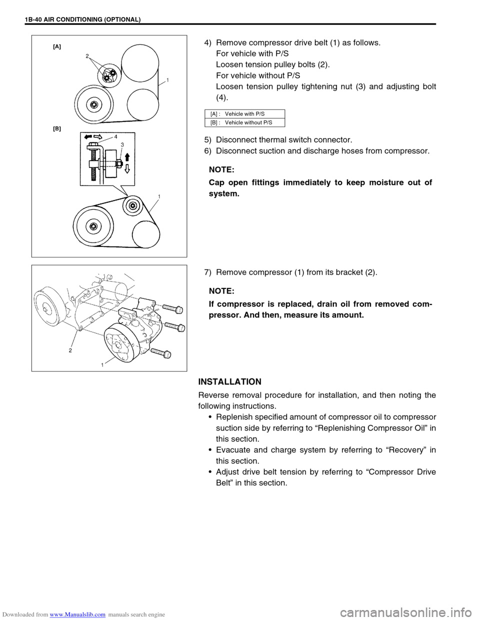
4) Remove compressor drive belt (1) as follows.
For vehicle with P/S
Loosen tension pulley bolts (2).
For vehicle without P/S
Loosen tension pulley tightening nut (3) and adjusting bolt
(4).
5) Disconnect thermal switch connector.
6) Disconnect suction and discharge hoses from compressor.
7) Remove compressor (1) from its bracket (2).
INSTALLATION
Reverse removal procedure for installation, and then noting the
following instructions.
Replenish specified amount of compressor oil to compressor
suction side by referring to “Replenishing Compressor Oil” in
this section.
Evacuate and charge system by referring to “Recovery” in
this section.
Adjust drive belt tension by referring to “Compressor Drive
Belt” in this section.
[A] : Vehicle with P/S
[B] : Vehicle without P/S
NOTE:
Cap open fittings immediately to keep moisture out of
system.
NOTE:
If compressor is replaced, drain oil from removed com-
pressor. And then, measure its amount.
Page 102 of 687
Downloaded from www.Manualslib.com manuals search engine AIR CONDITIONING (OPTIONAL) 1B-41
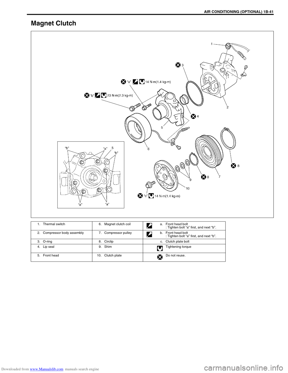
Magnet Clutch
1. Thermal switch 6. Magnet clutch coil a. Front head bolt
: Tighten bolt “a” first, and next “b”.
2. Compressor body assembly 7. Compressor pulley b. Front head bolt
: Tighten bolt “a” first, and next “b”.
3. O-ring 8. Circlip c. Clutch plate bolt
4. Lip seal 9. Shim Tightening torque
5. Front head 10. Clutch plate Do not reuse.
Page 103 of 687
Downloaded from www.Manualslib.com manuals search engine 1B-42 AIR CONDITIONING (OPTIONAL)
INSPECTION
Check clutch plate and clutch pulley for leaks of compressor
oil.
Check clutch bearing of compressor pulley for noise, wear
and grease leakage.
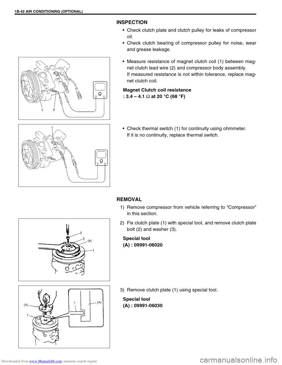
Measure resistance of magnet clutch coil (1) between mag-
net clutch lead wire (2) and compressor body assembly.
If measured resistance is not within tolerance, replace mag-
net clutch coil.
Magnet Clutch coil resistance
: 3.4 – 4.1
Ω at 20 °C (68 °F)
Check thermal switch (1) for continuity using ohmmeter.
If it is no continuity, replace thermal switch.
REMOVAL
1) Remove compressor from vehicle referring to “Compressor”
in this section.
2) Fix clutch plate (1) with special tool, and remove clutch plate
bolt (2) and washer (3).
Special tool
(A) : 09991-06020
3) Remove clutch plate (1) using special tool.
Special tool
(A) : 09991-06030
Page 104 of 687
Downloaded from www.Manualslib.com manuals search engine AIR CONDITIONING (OPTIONAL) 1B-43
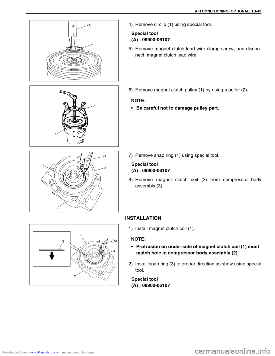
4) Remove circlip (1) using special tool.
Special tool
(A) : 09900-06107
5) Remove magnet clutch lead wire clamp screw, and discon-
nect magnet clutch lead wire.
6) Remove magnet clutch pulley (1) by using a puller (2).
7) Remove snap ring (1) using special tool.
Special tool
(A) : 09900-06107
8) Remove magnet clutch coil (2) from compressor body
assembly (3).
INSTALLATION
1) Install magnet clutch coil (1).
2) Install snap ring (3) to proper direction as show using special
tool.
Special tool
(A) : 09900-06107
NOTE:
Be careful not to damage pulley part.
NOTE:
Protrusion on under side of magnet clutch coil (1) must
match hole in compressor body assembly (2).
Page 105 of 687
Downloaded from www.Manualslib.com manuals search engine 1B-44 AIR CONDITIONING (OPTIONAL)
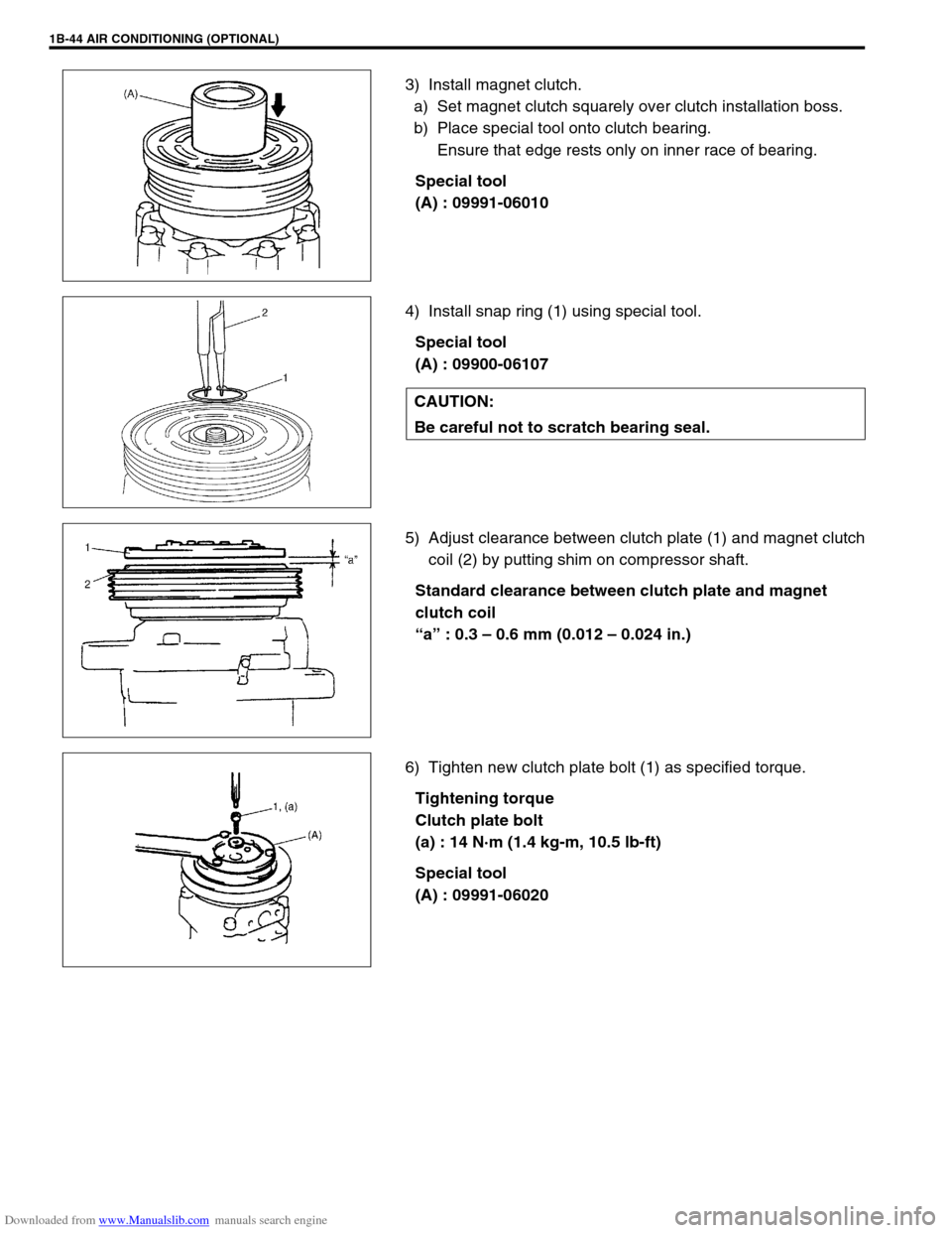
3) Install magnet clutch.
a) Set magnet clutch squarely over clutch installation boss.
b) Place special tool onto clutch bearing.
Ensure that edge rests only on inner race of bearing.
Special tool
(A) : 09991-06010
4) Install snap ring (1) using special tool.
Special tool
(A) : 09900-06107
5) Adjust clearance between clutch plate (1) and magnet clutch
coil (2) by putting shim on compressor shaft.
Standard clearance between clutch plate and magnet
clutch coil
“a” : 0.3 – 0.6 mm (0.012 – 0.024 in.)
6) Tighten new clutch plate bolt (1) as specified torque.
Tightening torque
Clutch plate bolt
(a) : 14 N·m (1.4 kg-m, 10.5 lb-ft)
Special tool
(A) : 09991-06020
CAUTION:
Be careful not to scratch bearing seal.
Page 106 of 687

Downloaded from www.Manualslib.com manuals search engine AIR CONDITIONING (OPTIONAL) 1B-45
Lip Type Seal
REMOVAL
1) Remove magnet clutch referring to “Magnet Clutch” in this
section.
2) Remove front head mounting bolts (10 pcs).
3) Remove front head (1) by pushing compressor shaft (2).
4) Remove O-ring (5).
5) Remove lip type seal from front head (1) using bearing
remover (2).
INSTALLATION
1) Press-fit lip type seal (1) into front head (2) using special
tool.
Special tool
(A) : 09991-06050
1. Front head
NOTE:
Be careful not to remove cylinder (3) from compressor
body assembly (4).
CAUTION:
Do not reuse lip seal (1) once removed from compressor.
Page 107 of 687
Downloaded from www.Manualslib.com manuals search engine 1B-46 AIR CONDITIONING (OPTIONAL)
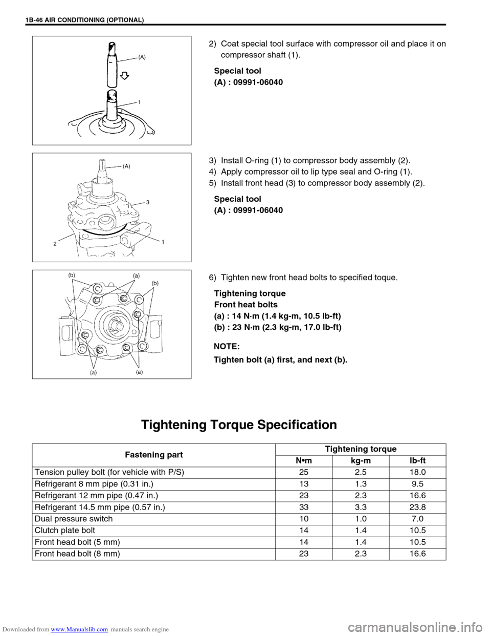
2) Coat special tool surface with compressor oil and place it on
compressor shaft (1).
Special tool
(A) : 09991-06040
3) Install O-ring (1) to compressor body assembly (2).
4) Apply compressor oil to lip type seal and O-ring (1).
5) Install front head (3) to compressor body assembly (2).
Special tool
(A) : 09991-06040
6) Tighten new front head bolts to specified toque.
Tightening torque
Front heat bolts
(a) : 14 N·m (1.4 kg-m, 10.5 lb-ft)
(b) : 23 N·m (2.3 kg-m, 17.0 lb-ft)
Tightening Torque Specification
NOTE:
Tighten bolt (a) first, and next (b).
Fastening partTightening torque
Nm kg-m lb-ft
Tension pulley bolt (for vehicle with P/S) 25 2.5 18.0
Refrigerant 8 mm pipe (0.31 in.) 13 1.3 9.5
Refrigerant 12 mm pipe (0.47 in.) 23 2.3 16.6
Refrigerant 14.5 mm pipe (0.57 in.) 33 3.3 23.8
Dual pressure switch 10 1.0 7.0
Clutch plate bolt 14 1.4 10.5
Front head bolt (5 mm) 14 1.4 10.5
Front head bolt (8 mm) 23 2.3 16.6
Page 108 of 687
Downloaded from www.Manualslib.com manuals search engine AIR CONDITIONING (OPTIONAL) 1B-47
Required Service Materials
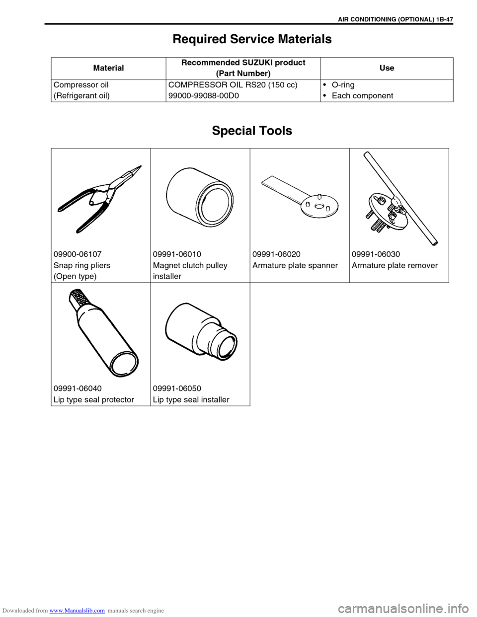
Special Tools
MaterialRecommended SUZUKI product
(Part Number)Use
Compressor oil
(Refrigerant oil)COMPRESSOR OIL RS20 (150 cc)
99000-99088-00D0O-ring
Each component
09900-06107 09991-06010 09991-06020 09991-06030
Snap ring pliers
(Open type)Magnet clutch pulley
installerArmature plate spanner Armature plate remover
09991-06040 09991-06050
Lip type seal protector Lip type seal installer
Page 109 of 687

Downloaded from www.Manualslib.com manuals search engine 1B-48 AIR CONDITIONING (OPTIONAL)
Page 110 of 687
Downloaded from www.Manualslib.com manuals search engine STEERING, SUSPENSION, WHEELS AND TIRES 3-1
6F1
6F2
6G
3
7B1
7C1
7B1
7B1
7C1
7D
7E
7F
8A
8B
8C
8D
8E
9
10
10A
10B
SECTION 3
STEERING, SUSPENSION, WHEELS AND TIRES
DIAGNOSIS . . . . . . . . . . . . . . . . . . . . . . . . . . . . . . . . . . . . . . . . . . . . . . . . . . . . . . . . . . . . . . . . . 3-1
FRONT END ALIGNMENT . . . . . . . . . . . . . . . . . . . . . . . . . . . . . . . . . . . . . . . . . . . . . . . . . . . . . . Section 3A-1
STEERING GEAR BOX AND LINKAGE . . . . . . . . . . . . . . . . . . . . . . . . . . . . . . . . . . . . . . . . . . . Section 3B-1
POWER STEERING SYSTEM (IF EQUIPPED) . . . . . . . . . . . . . . . . . . . . . . . . . . . . . . . . . . . . . . Section 3B1-1
STEERING WHEEL, COLUMN AND SHAFT . . . . . . . . . . . . . . . . . . . . . . . . . . . . . . . . . . . . . . . Section 3C-1
FRONT SUSPENSION . . . . . . . . . . . . . . . . . . . . . . . . . . . . . . . . . . . . . . . . . . . . . . . . . . . . . . . . . Section 3D-1
REAR SUSPENSION . . . . . . . . . . . . . . . . . . . . . . . . . . . . . . . . . . . . . . . . . . . . . . . . . . . . . . . . . . Section 3E-1
WHEELS AND TIRES . . . . . . . . . . . . . . . . . . . . . . . . . . . . . . . . . . . . . . . . . . . . . . . . . . . . . . . . . Section 3F-1
CONTENTS
General Diagnosis............................................. 3-2
Diagnosis Table .............................................. 3-2
Tire Diagnosis ................................................... 3-5
Irregular and/or Premature Wear .................... 3-5Wear Indicators ............................................... 3-5
Radial Tire Waddle ......................................... 3-5
Radial Tire Lead.............................................. 3-7
Vibration Diagnosis .......................................... 3-7