SUZUKI MARUTI 2005 1.G Owner's Manual
Manufacturer: SUZUKI, Model Year: 2005, Model line: MARUTI, Model: SUZUKI MARUTI 2005 1.GPages: 136, PDF Size: 2.93 MB
Page 21 of 136
Downloaded from www.Manualslib.com manuals search engine 2183K
BEFORE DRIVING
4-9
Programming Shock Sensor ON/OFF
a) Open the Driver Door of your vehicle.
b) With your vehicle key in the key cylin-
der, turn IGN ON and then switch it
OFF.
c) Press and release the Security switch
Four times.
d) Press and hold the Security switch.
e) Four-chirp sound confirms entry into
Shock Sensor ON/OFF programming
mode.
f) Press the Key Lock button (while hold-
ing the Security switch), a single chirp
sound confirms the mode changed to
shock sensor ON.
g) Two-Siren chirp sound confirms the
mode changed to shock sensor OFF.
h) Release the Security switch.
i) Turn the IGN ON.
Shock Sensor Sensitivity
Adjustment via Key
Full Blast Adjustment
Full Blast can be adjustment in 16 levels
as mentioned below.
a) Press Unlock button on Key to Unlock/
Disarm the System.
b) Press Lock button on Key to Lock/Arm
the System.
c) Within 5 sec press Lock & Unlock but-
ton simultaneously for at least 2 sec.Siren will give long chirp to confirm entry
into sensitivity adjustment mode
i) Press Key Lock button to adjust the
sensitivity one step lower. Siren will
give one chirp every time lock button
is pressed till at level 0 where it will
give a long chirp. When adjust to level
0, Full Blast will turn OFF
ii) Press Key unlock button to adjust the
sensitivity one step higher. Siren will
give two chirp every time unlock
button is pressed till at level 16 where
it will give a long chirp.
Pre-warn Adjustment
Pre-warn can be adjusted in 16 levels as
mentioned below:
a) Press Lock button on Key to Lock/Arm
the System
b) Press Unlock button on Key to Unlock/
Disarm the System
c) Within 5 sec press Lock & Unlock but-
ton simultaneously for at least 2 sec.
Siren will give Long chirp to confirm
entry into Sensitivity Adjustment Mode.
i) Press Key Lock button to adjust the
sensitivity one step lower. Siren will
give one chirp every time lock button
is pressed till at level 0 where it will
give a long chirp. When adjusts to
level 0, prewarn will turn OFF.ii) Press Key Unlock button to adjust the
sensitivity one step higher. Siren will
give two Chirp every time Unlock
button is pressed till at level 16 where
it will give a long chirp.
Programming of Valet Mode
This feature can be programmed as follows:
i) Close the driver door.
ii) Turn IGN ON-OFF quickly.
iii) Press and hold Security switch for 3 sec
minimum, LED will turn ON for 1 minute.
Repeat step 1-3 to come out of Valet Mode,
1 Siren chirp sound will indicate Valet Mode
OFF.
Program Customer Pincode
(Personalised Pincode)
The Personalised 4-digit number can be
changed from the factory default to ensure
Personalised Security.
Pin code entry
a) Disarm the system.
b) Open the Driver Door.
c) Turn IGN ON then OFF.
d) Within 5 seconds press and release
Valet switch 5 times. A short chirp fol-
lowed by long chirps confirms entry into
Pin Code programming mode.
Page 22 of 136
Downloaded from www.Manualslib.com manuals search engine 2283K
BEFORE DRIVING
4-10e) Press Lock button on Key, after a sin-
gle chirp enter the First digit (with in 1-
9) by pressing Valet switch (for e.g. to
enter 2 press and release Valet switch
two times).
f) Press Lock button on Key, after two
chirp enter the Second digit (with in 1-
9) by pressing Valet switch.
g) Press Lock button on Key, after 3-chirps
enter the Third digit (with in 1-9) by
Pressing Valet switch.
h) Press Lock button on Key, after 4-chirps
enter the Fourth digit (with in 1-9) by
pressing Valet switch.
Emergency Disarm by personalised pin
code
The Personalised 4- Digit Pin Code acts as
a secret Key, to Emergency Disarm the
vehicle.
a) Turn the IGN ON, OFF and then ON.
b) Enter the First digit (for e. g. to enter 2
press and release Valet switch twice)
c) Turn the IGN OFF then ON.
d) Enter the Second digit.
e) Turn the IGN OFF and then ON.
f) Enter the Third Digit.
g) Turn the IGN OFF and then ON
h) Enter the Last Digit.
i) Turn the IGN OFF and then ON.
The vehicle will get disarmed.
Page 23 of 136
Downloaded from www.Manualslib.com manuals search engine 2383K
BEFORE DRIVING
4-11
SYMPTOMS
Transmitter can't activate or deactivate the
center lock system or alarm
Control distance of the transmitter becomes
nearer (less than 10m)
It is difficult to activate or deactivate the
system in certain area using the transmitter.
Open door(s), front bonnet not trigger the
alarm.
Siren does not sound when alarm is
triggered.Troubleshooting
PROBABLE CAUSES
1. Battery of the transmitter is weak.
2. Transmitter is exposed to water or it is
wet.
3. In-line supply fuse for controller is blown
in the vehicle.
4. In case if any door is open or door
sensor is shorted with the body ground,
remote will not activate the central
locking/ alarm system.
1. Battery of the transmitter is weak.
2. Strong RF interference. (e.g. Radio
Towers, High Voltage Transmission line
near by)
1. The strong interference caused by
excessive RF activity in a particular area
1. The contact point of the door(s), front
bonnet of rear boot switch is faulty.
2. The connection of door(s), front bonnet
of rear boot switch is loose.
1. The connection of the siren wire is
loose.
2. Siren is faulty.REMEDIES
1. Replace the battery.
2. Dry the transmitter and fine-tuning may
be necessary.
3. Replate the fuse.
4. Check if all doors are properly closed
and door switch functioning is O.K.
1. Replace the battery.
2. Drive the vehicle away from the parti-
cular spot and re-test the control dis-
tance.
1. The interference is temporary and only
while the vehicle is in that area.
1. Replace the defective Switch.
2. Make proper connection.
1. Make proper connection.
2. Change the siren.
Page 24 of 136
Downloaded from www.Manualslib.com manuals search engine 2483K
BEFORE DRIVING
4-12WindowsManual Window Control
(if equipped)Raise or lower the door windows by turning
the handle located on the door panel.Electric Window Controls
(if equipped)The electric windows can only be operated
when the ignition switch is in the “ON” position.
Driver’s door
83K-02-02183K-02-022
The driver’s door has switches (1), (2), (3),
(4) to operate the driver’s window, the front
passenger’s window, the rear left window
and the rear right window, respectively.
Passenger’s door (if equipped)
The passenger’s door has a switch (6) to
operate that passenger’s window.
83K-02-023
EXAMPLE
EXAMPLEEXAMPLE
83K-02-024
To open a window, push the top part of the
switch and to close the window, lift up the
top part of the switch.
The driver’s window has an “auto-down”
feature for added convenience (at toll
booths or drive-through restaurants, for
example). This means you can open the
window without holding the window switch
in the “Down” position. Press the driver’s
window switch completely down and release
it. To stop the window before it reaches the
bottom, pull the switch up briefly.
Lock switch (if equipped)
The driver’s door also has a lock switch (5)
for the passenger’s windows. When you
push in the lock switch, the passenger’s
windows can not be raised or lowered by
operating any of the switches (2), (3), (4)
Page 25 of 136
Downloaded from www.Manualslib.com manuals search engine 2583K
BEFORE DRIVING
4-13
or (6). To restore normal operation, release
the lock switch by pushing again.
w ww w
w WARNING
You should always lock the passen-
ger’s window operation when there
are children in the vehicle. Children
can be seriously injured if they get
part of their body caught by the
window during operation.
To avoid injuring an occupant by
window entrapment, be sure no part
of the occupant’s body such as
hands or head is in the path of the
electric windows when closing them.
Always remove the ignition key
when leaving the vehicle even if a
short time. Also do not leave chil-
dren alone in a parked vehicle.
Unattended children could use the
electric window switches and get
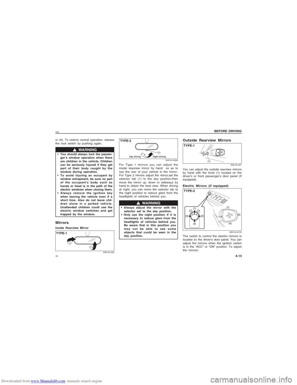
trapped by the window.MirrorsInside Rearview Mirror
83K-02-026
83K-02-026A
w ww w
w WARNING
selector set to the day position.
necessary to reduce glare from the
headlights of vehicles behind you.
Be aware that in this position you
may not be able to see some
objects that could be seen in the
day position.You can adjust the outside rearview mirrors
by hand with the knob (1) located on the
driver’s or front passenger’s door panel (If
equipped).
83K-02-027
Outside Rearview MirrorsTYPE-1
83K-02-027A
TYPE-2 Electric Mirrors (if equipped)The switch to control the electric mirrors is
located on the driver’s door panel. You can
adjust the mirrors when the ignition switch
is in the “ACC” or “ON” position. To adjust
the mirrors: For Type 1 mirrors you can adjust the
inside rearview mirror by hand so as to
see the rear of your vehicle in the mirror.
For Type 2 mirrors adjust the mirror,set the
selector tab (1) to the day position,then
move the mirror up, down or sideways by
hand to obtain the best view. When driving
at night, you can move the selector tab to
the night position to reduce glare from the
headlights of vehicles behind you.
TYPE-1TYPE-2
Page 26 of 136
Downloaded from www.Manualslib.com manuals search engine 2683K
BEFORE DRIVING
4-14
NOTE:
The defogger will work only when the
engine is running.
The defogger will automatically turn off
after the defogger remains on for 15 min-
utes to prevent discharging of the battery.Front SeatsSeat Adjustment
w ww w
w WARNING
Never attempt to adjust the driver’s
seat or seatback while driving. The
seat or seatback could move unex-
pectedly, causing loss of control.
Make sure that the driver’s seat and
seatback are properly adjusted before
you start driving.
w ww w
w WARNING
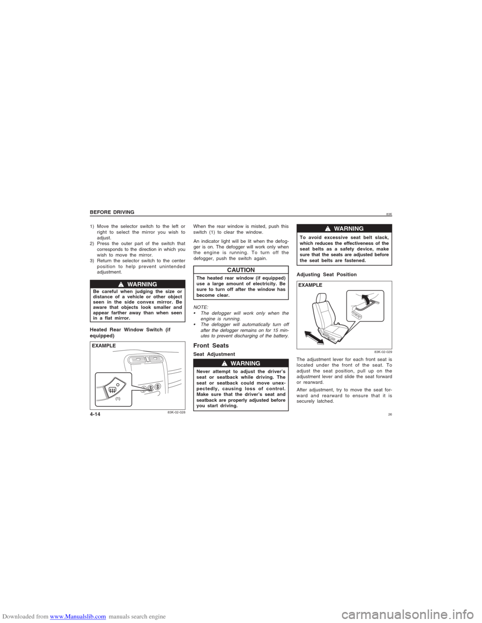
Heated Rear Window Switch (if
equipped)
83K-02-028
EXAMPLE
An indicator light will be lit when the defog-
ger is on. The defogger will work only when
the engine is running. To turn off the
defogger, push the switch again.
CAUTION
The heated rear window (if equipped)
use a large amount of electricity. Be
sure to turn off after the window has
become clear. When the rear window is misted, push this
switch (1) to clear the window.
Adjusting Seat PositionThe adjustment lever for each front seat is
located under the front of the seat. To
adjust the seat position, pull up on the
adjustment lever and slide the seat forward
or rearward.
After adjustment, try to move the seat for-
ward and rearward to ensure that it is
securely latched.
83K-02-029
EXAMPLE
1) Move the selector switch to the left or
right to select the mirror you wish to
adjust.
2) Press the outer part of the switch that
corresponds to the direction in which you
wish to move the mirror.
3) Return the selector switch to the center
position to help prevent unintended
adjustment.
w ww w
w WARNING
Be careful when judging the size or
distance of a vehicle or other object
seen in the side convex mirror. Be
aware that objects look smaller and
appear farther away than when seen
in a flat mirror.To avoid excessive seat belt slack,
which reduces the effectiveness of the
seat belts as a safety device, make
sure that the seats are adjusted before
the seat belts are fastened.
Page 27 of 136

Downloaded from www.Manualslib.com manuals search engine 2783K
BEFORE DRIVING
4-15
w ww w
w WARNING
Never drive the vehicle with the
head restraints removed.
Do not attempt to adjust the head
restraint while driving.
83K-02-031
To adjust the seatback angle of front seats,
pull up the lever on the outboard side of
the seat, move the seatback to the desired
position, and release the lever to lock the
seatback in place.Adjustable Head Restraints
(if equipped)Head restraints are designed to help reduce
the risk of neck injuries in the case of an
accident.
NOTE:
It may be necessary to recline the seatback
to provide enough overhead clearance to
remove the head restraint.
83K-02-032
Adjust the head restraint to the position
which places the center of the head restraint
closest to the top of your ears. If this is not
possible for very tall passengers, adjust the
head restraint as high as possible.
EXAMPLE
Seat Height Adjuster (if equipped)If the driver’s seat is equipped with a seat
height adjuster lever on the outboard side
of the seat, raise or lower the seat by pull-
ing up or down the adjuster lever.Adjusting Seatbacks
83K-02-030
w ww w
w WARNING
All seatbacks should always be in an
upright position when driving, or seat
belt effectiveness may be reduced.
Seat belts are designed to offer maxi-
mum protection when seatbacks are in
the upright position.EXAMPLE
Page 28 of 136

Downloaded from www.Manualslib.com manuals search engine 2883K
BEFORE DRIVING
4-16
Rear SeatsAdjustable Head Restraints
(if equipped)
83K-02-034
To raise the rear head restraint, pull upward
on the restraint until it clicks. To lower the
restraint, push down on the restraint while
holding in the lock lever. If a head restraint
is required to be removed (for cleaning,
replacement, etc.), push in the lock lever
and pull the head restraint all the way out.
When installing a child restraint system,
raise the head restraint to the most upper
position.
Folding Rear Seats (if equipped)The rear seat(s) of your vehicle can be
folded forward to provide additional cargo
space.
To fold the rear seats forward:
1) Hook the webbing and the latch plate of
the outboard lap-shoulder belts in the
belt hangers.
83K-02-035
CAUTION
When you move a seatback, make
sure both the latch plate and the
belt webbing are hooked in the seat
belt hangers so the seat belts are
not caught by the seatback, seat
hinge, or seat latch. This helps pre-
vent damage to the belt system.
V
Front
To raise the front head restraint, pull
upward on the restraint until it clicks. To
lower the restraint, push down on the
restraint while holding in the lock lever. If
a head restraint must be removed (for
cleaning, replacement, etc.), push in the
lock lever and pull the head restraint all the
way out.
83K-02-033
EXAMPLE
Page 29 of 136
Downloaded from www.Manualslib.com manuals search engine 2983K
BEFORE DRIVING
4-17
NOTICE
After folding the rear seatback for-
ward, do not allow any foreign mate-
rial to enter the lock opening. This
may cause damage to the inside of
the lock and prevent the seatback
from being locked securely.
w ww w
w WARNING
If you need to carry cargo in the pas-
senger compartment with the rear seat
back folded forward, be sure to secure
the cargo or it may be thrown about,
causing injury. Never pile cargo higher
than the seatbacks.
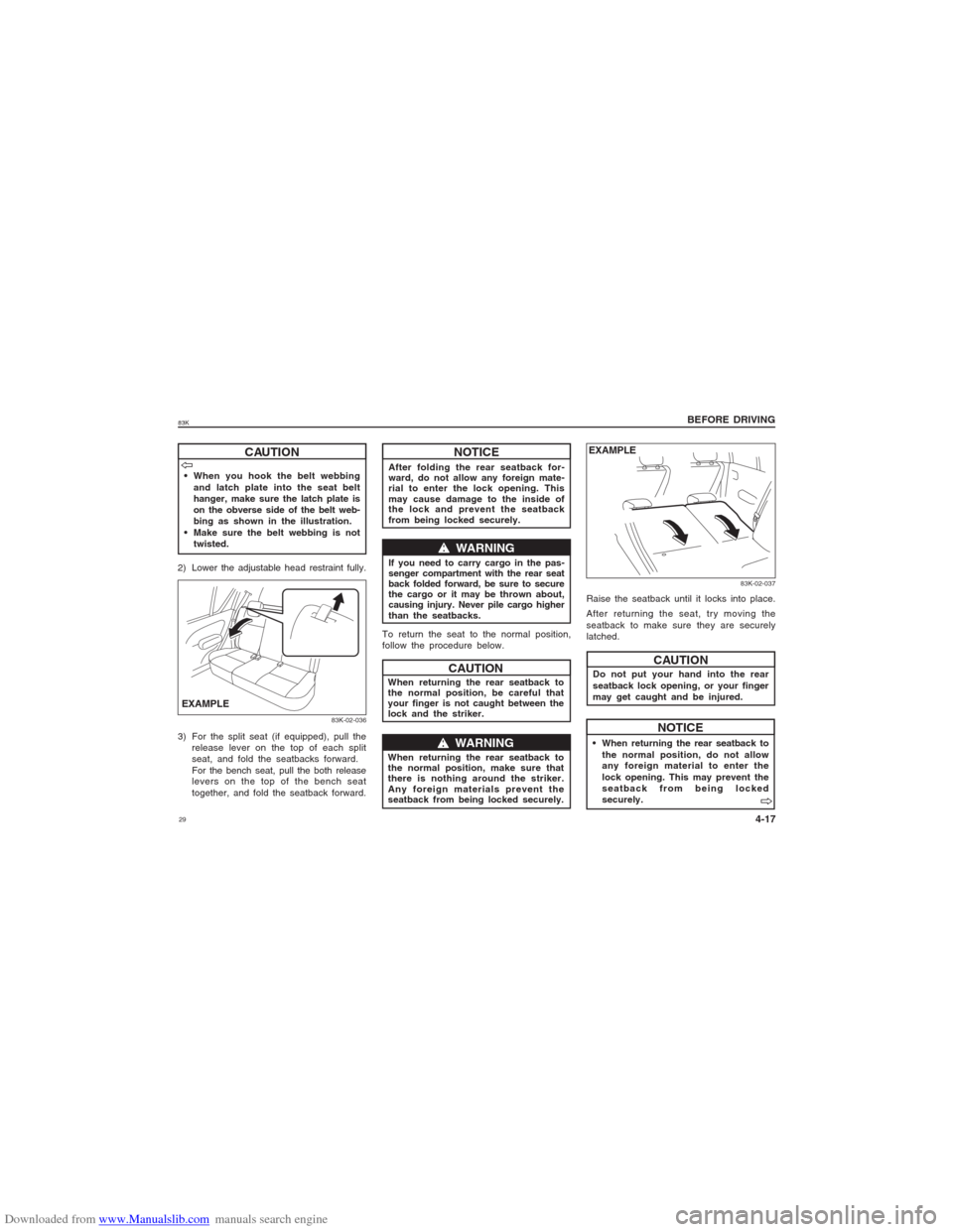
To return the seat to the normal position,
follow the procedure below.
When returning the rear seatback to
the normal position, be careful that
your finger is not caught between the
lock and the striker.
When returning the rear seatback to
the normal position, make sure that
there is nothing around the striker.
Any foreign materials prevent the
seatback from being locked securely.
83K-02-037
Raise the seatback until it locks into place.
After returning the seat, try moving the
seatback to make sure they are securely
latched.
Do not put your hand into the rear
seatback lock opening, or your finger
may get caught and be injured.
When returning the rear seatback to
the normal position, do not allow
any foreign material to enter the
lock opening. This may prevent the
seatback from being locked
securely.
NOTICE
EXAMPLE
When you hook the belt webbing
and latch plate into the seat belt
hanger, make sure the latch plate is
on the obverse side of the belt web-
bing as shown in the illustration.
Make sure the belt webbing is not
twisted.
CAUTION
2) Lower the adjustable head restraint fully.
83K-02-036
3) For the split seat (if equipped), pull the
release lever on the top of each split
seat, and fold the seatbacks forward.
For the bench seat, pull the both release
levers on the top of the bench seat
together, and fold the seatback forward.EXAMPLEV VV V
V
CAUTIONw ww w
w WARNING
CAUTION
V VV V
V
Page 30 of 136
Downloaded from www.Manualslib.com manuals search engine 3083K
BEFORE DRIVING
4-18
w ww w
w WARNING
An air bag supplements, or adds to,
the frontal crash protection offered by
seat belts. The driver and all pas-
sengers must be properly restrained
by wearing seat belts at all times,
whether or not an air bag is mounted
at their seating position, to minimize
the risk of severe injury or death in
the event of a crash.
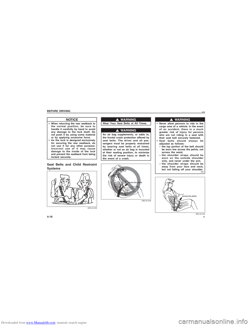
83K-02-039
w ww w
w WARNING
Never allow persons to ride in the
cargo area of a vehicle. In the event
of an accident, there is a much
greater risk of injury for persons
who are not riding in a seat with
their seat belt securely fastened.
Seat belts should always be
adjusted as follows:
– the lap portion of the belt should
be worn low across the pelvis, not
across the waist.
– the shoulder straps should be
worn on the outside shoulder
only, and never under the arm.
– the shoulder straps should be
away from your face and neck,
but not falling off your shoulder.
83K-02-040
NOTICE
When returning the rear seatback to
the normal position, be sure to
handle it carefully by hand to avoid
any damage to the lock itself. Do
not push it by using some material
or by applying excessive force.
As the lock is designed exclusively
for securing the rear seatback, do
not use it for any other purpose.
Incorrect use of it may cause
damage to the inside of the lock
and prevent the seatback from being
locked securely.Seat Belts and Child Restraint
Systems
w ww w
w WARNING
Wear Your Seat Belts at All Times.
83K-02-038
V VV V
V