Torque SUZUKI SWIFT 2000 1.G RG413 Service Workshop Manual
[x] Cancel search | Manufacturer: SUZUKI, Model Year: 2000, Model line: SWIFT, Model: SUZUKI SWIFT 2000 1.GPages: 698, PDF Size: 16.01 MB
Page 321 of 698
5-48 BRAKES
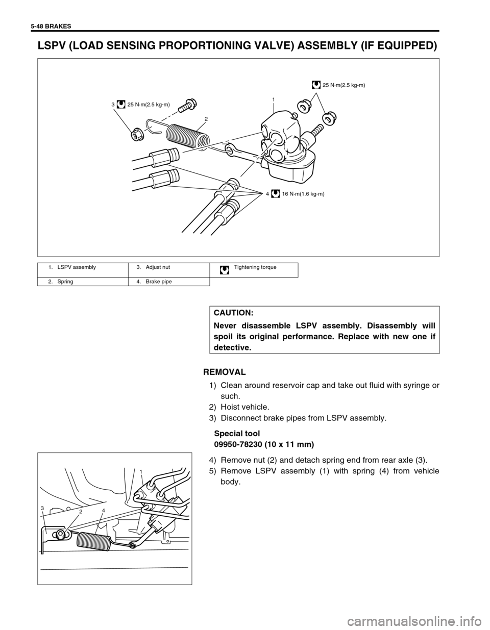
LSPV (LOAD SENSING PROPORTIONING VALVE) ASSEMBLY (IF EQUIPPED)
REMOVAL
1) Clean around reservoir cap and take out fluid with syringe or
such.
2) Hoist vehicle.
3) Disconnect brake pipes from LSPV assembly.
Special tool
09950-78230 (10 x 11 mm)
4) Remove nut (2) and detach spring end from rear axle (3).
5) Remove LSPV assembly (1) with spring (4) from vehicle
body.
1. LSPV assembly 3. Adjust nut Tightening torque
2. Spring 4. Brake pipe
CAUTION:
Never disassemble LSPV assembly. Disassembly will
spoil its original performance. Replace with new one if
detective.
3
21
25 N·m(2.5 kg-m)
4 16 N·m(1.6 kg-m)
25 N·m(2.5 kg-m)
3
24
1
Page 322 of 698
BRAKES 5-49
INSTALLATION
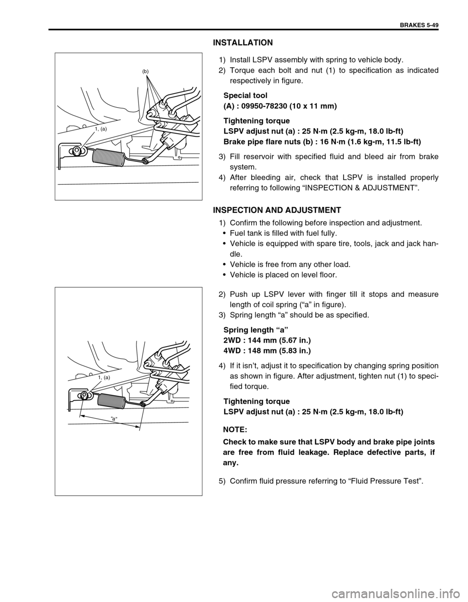
1) Install LSPV assembly with spring to vehicle body.
2) Torque each bolt and nut (1) to specification as indicated
respectively in figure.
Special tool
(A) : 09950-78230 (10 x 11 mm)
Tightening torque
LSPV adjust nut (a) : 25 N·m (2.5 kg-m, 18.0 lb-ft)
Brake pipe flare nuts (b) : 16 N·m (1.6 kg-m, 11.5 lb-ft)
3) Fill reservoir with specified fluid and bleed air from brake
system.
4) After bleeding air, check that LSPV is installed properly
referring to following “INSPECTION & ADJUSTMENT”.
INSPECTION AND ADJUSTMENT
1) Confirm the following before inspection and adjustment.
Fuel tank is filled with fuel fully.
Vehicle is equipped with spare tire, tools, jack and jack han-
dle.
Vehicle is free from any other load.
Vehicle is placed on level floor.
2) Push up LSPV lever with finger till it stops and measure
length of coil spring (“a” in figure).
3) Spring length “a” should be as specified.
Spring length “a”
2WD : 144 mm (5.67 in.)
4WD : 148 mm (5.83 in.)
4) If it isn’t, adjust it to specification by changing spring position
as shown in figure. After adjustment, tighten nut (1) to speci-
fied torque.
Tightening torque
LSPV adjust nut (a) : 25 N·m (2.5 kg-m, 18.0 lb-ft)
5) Confirm fluid pressure referring to “Fluid Pressure Test”.
1, (a)
(b)
NOTE:
Check to make sure that LSPV body and brake pipe joints
are free from fluid leakage. Replace defective parts, if
any.
1, (a)
“a”
Page 326 of 698
ANTILOCK BRAKE SYSTEM (ABS) 5E-1
6F1
6F2
6G
6H
6K
7A
7A1
7B1
7C1
7D
7E
7F
8A
8B
8C
8D
8E
5E
9
10
10A
10B
SECTION 5E
ANTILOCK BRAKE SYSTEM (ABS)
CONTENTS
GENERAL DESCRIPTION .............................. 5E-2
COMPONENTS/PARTS LOCATION AND
BRAKE HOSE/PIPE ROUTING ................... 5E-2
SYSTEM SCHEMATIC ................................ 5E-4
ABS HYDRAULIC UNIT/CONTROL
MODULE ASSEMBLY ................................. 5E-5
SELF-DIAGNOSIS FUNCTION................ 5E-5
FAIL-SAFE FUNCTION............................ 5E-5
SYSTEM CIRCUIT ....................................... 5E-6
DIAGNOSIS ..................................................... 5E-8
PRECAUTION IN DIAGNOSING
TROUBLES .................................................. 5E-8
ABS DIAGNOSTIC FLOW TABLE ............... 5E-9
ABS WARNING LAMP CHECK ................. 5E-12
EBD WARNING LAMP (BRAKE
WARNING LAMP) CHECK ........................ 5E-12
TABLE – A ABS WARNING LAMP
CIRCUIT CHECK – LAMP DOES NOT
COME “ON” AT IGNITION SWITCH ON.... 5E-13
TABLE – B ABS WARNING LAMP
CIRCUIT CHECK – LAMP COMES
“ON” STEADY ............................................ 5E-14TABLE – C ABS WARNING LAMP
CIRCUIT CHECK – THE LAMP FLASHES
CONTINUOUSLY WHILE IGNITION
SWITCH IS ON .......................................... 5E-15
TABLE – D CODE (DTC) IS NOT
OUTPUTTED EVEN WITH DIAGNOSIS
SWITCH TERMINAL CONNECTED TO
GROUND ................................................... 5E-16
TABLE – E EBD WARNING LAMP
(BRAKE WARNING LAMP) CHECK
– LAMP COMES “ON” STEADY ................ 5E-17
DIAGNOSTIC TROUBLE CODE
(DTC) CHECK (USING ABS WARNING
LAMP) ........................................................ 5E-18
DIAGNOSTIC TROUBLE CODE (DTC)
CHECK (USING SUZUKI SCAN TOOL).... 5E-19
DIAGNOSTIC TROUBLE CODE
(DTC) CLEARANCE .................................. 5E-19
DIAGNOSTIC TROUBLE CODE (DTC)
TABLE........................................................ 5E-20
DTC C1013 (DTC 13) – SYSTEM
SPECIFICATIONS DIFFERENT FROM ABS
CONTROL MODULE SPECIFICATIONS .. 5E-22 WARNING:
For vehicles equipped with Supplemental Restraint (Air Bag) System :
Service on and around the air bag system components or wiring must be performed only by an
authorized SUZUKI dealer. Refer to “Air Bag System Components and Wiring Location View” under
“General Description” in air bag system section in order to confirm whether you are performing ser-
vice on or near the air bag system components or wiring. Please observe all WARNINGS and “Ser-
vice Precautions” under “On-Vehicle Service” in air bag system section before performing service
on or around the air bag system components or wiring. Failure to follow WARNINGS could result in
unintentional activation of the system or could render the system inoperative. Either of these two
conditions may result in severe injury.
Technical service work must be started at least 90 seconds after the ignition switch is turned to the
“LOCK” position and the negative cable is disconnected from the battery. Otherwise, the system
may be activated by reserve energy in the Sensing and Diagnostic Module (SDM).
NOTE:
All brake fasteners are important attaching parts in that they could affect the performance of vital
parts and systems, and/or could result in major repair expense. They must be replaced with one of
same part number or with an equivalent part if replacement becomes necessary. Do not use a replace-
ment part of lesser quality or substitute design. Torque values must be used as specified during reas-
sembly to assure proper retention of all parts. There is to be no welding as it may result in extensive
damage and weakening of the metal.
Page 350 of 698
ANTILOCK BRAKE SYSTEM (ABS) 5E-25
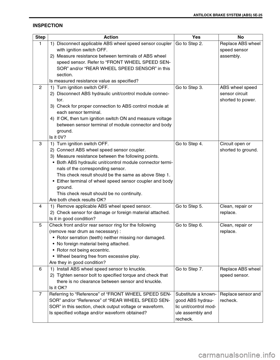
INSPECTION
Step Action Yes No
1 1) Disconnect applicable ABS wheel speed sensor coupler
with ignition switch OFF.
2) Measure resistance between terminals of ABS wheel
speed sensor. Refer to “FRONT WHEEL SPEED SEN-
SOR” and/or “REAR WHEEL SPEED SENSOR” in this
section.
Is measured resistance value as specified?Go to Step 2. Replace ABS wheel
speed sensor
assembly.
2 1) Turn ignition switch OFF.
2) Disconnect ABS hydraulic unit/control module connec-
tor.
3) Check for proper connection to ABS control module at
each sensor terminal.
4) If OK, then turn ignition switch ON and measure voltage
between sensor terminal of module connector and body
ground.
Is it 0V?Go to Step 3. ABS wheel speed
sensor circuit
shorted to power.
3 1) Turn ignition switch OFF.
2) Connect ABS wheel speed sensor coupler.
3) Measure resistance between the following points.
Both ABS hydraulic unit/control module connector termi-
nals of the corresponding sensor.
This check result should be the same as above Step 1.
Either terminal of wheel speed sensor coupler and body
ground.
This check result should be no continuity.
Are both check results OK?Go to Step 4. Circuit open or
shorted to ground.
4 1) Remove applicable ABS wheel speed sensor.
2) Check sensor for damage or foreign material attached.
Is it in good condition?Go to Step 5. Clean, repair or
replace.
5 Check front and/or rear sensor ring for the following
(remove rear drum as necessary) :
Rotor serration (teeth) neither missing nor damaged.
No foreign material being attached.
Rotor not being eccentric.
Wheel bearing free from excessive play.
Are they in good condition?Go to Step 6. Clean, repair or
replace.
6 1) Install ABS wheel speed sensor to knuckle.
2) Tighten sensor bolt to specified torque and check that
there is no clearance between sensor and knuckle.
Is it OK?Go to Step 7. Replace ABS wheel
speed sensor.
7 Referring to “Reference” of “FRONT WHEEL SPEED SEN-
SOR” and/or “Reference” of “REAR WHEEL SPEED SEN-
SOR” in this section, check output voltage or waveform.
Is specified voltage and/or waveform obtained?Substitute a known-
good ABS hydrau-
lic unit/control mod-
ule assembly and
recheck.Replace sensor and
recheck.
Page 359 of 698
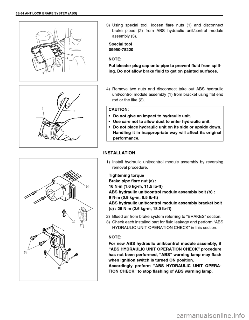
5E-34 ANTILOCK BRAKE SYSTEM (ABS)
3) Using special tool, loosen flare nuts (1) and disconnect
brake pipes (2) from ABS hydraulic unit/control module
assembly (3).
Special tool
09950-78220
4) Remove two nuts and disconnect take out ABS hydraulic
unit/control module assembly (1) from bracket using flat end
rod or the like (2).
INSTALLATION
1) Install hydraulic unit/control module assembly by reversing
removal procedure.
Tightening torque
Brake pipe flare nut (a) :
16 N·m (1.6 kg-m, 11.5 lb-ft)
ABS hydraulic unit/control module assembly bolt (b) :
9 N·m (0.9 kg-m, 6.5 lb-ft)
ABS hydraulic unit/control module assembly bracket bolt
(c) : 26 N·m (2.6 kg-m, 18.0 lb-ft)
2) Bleed air from brake system referring to “BRAKES” section.
3) Check each installed part for fluid leakage and perform “ABS
HYDRAULIC UNIT OPERATION CHECK” in this section. NOTE:
Put bleeder plug cap onto pipe to prevent fluid from spill-
ing. Do not allow brake fluid to get on painted surfaces.
312
CAUTION:
Do not give an impact to hydraulic unit.
Use care not to allow dust to enter hydraulic unit.
Do not place hydraulic unit on its side or upside down.
Handling it in inappropriate way will affect its original
performance.
NOTE:
For new ABS hydraulic unit/control module assembly, if
“ABS HYDRAULIC UNIT OPERATION CHECK” procedure
has not been performed, “ABS” warning lamp may flash
when ignition switch is turned ON position.
Accordingly preform “ABS HYDRAULIC UNIT OPERA-
TION CHECK” to stop flashing of ABS warning lamp.
(b)
(c) (b)(a)
Page 362 of 698
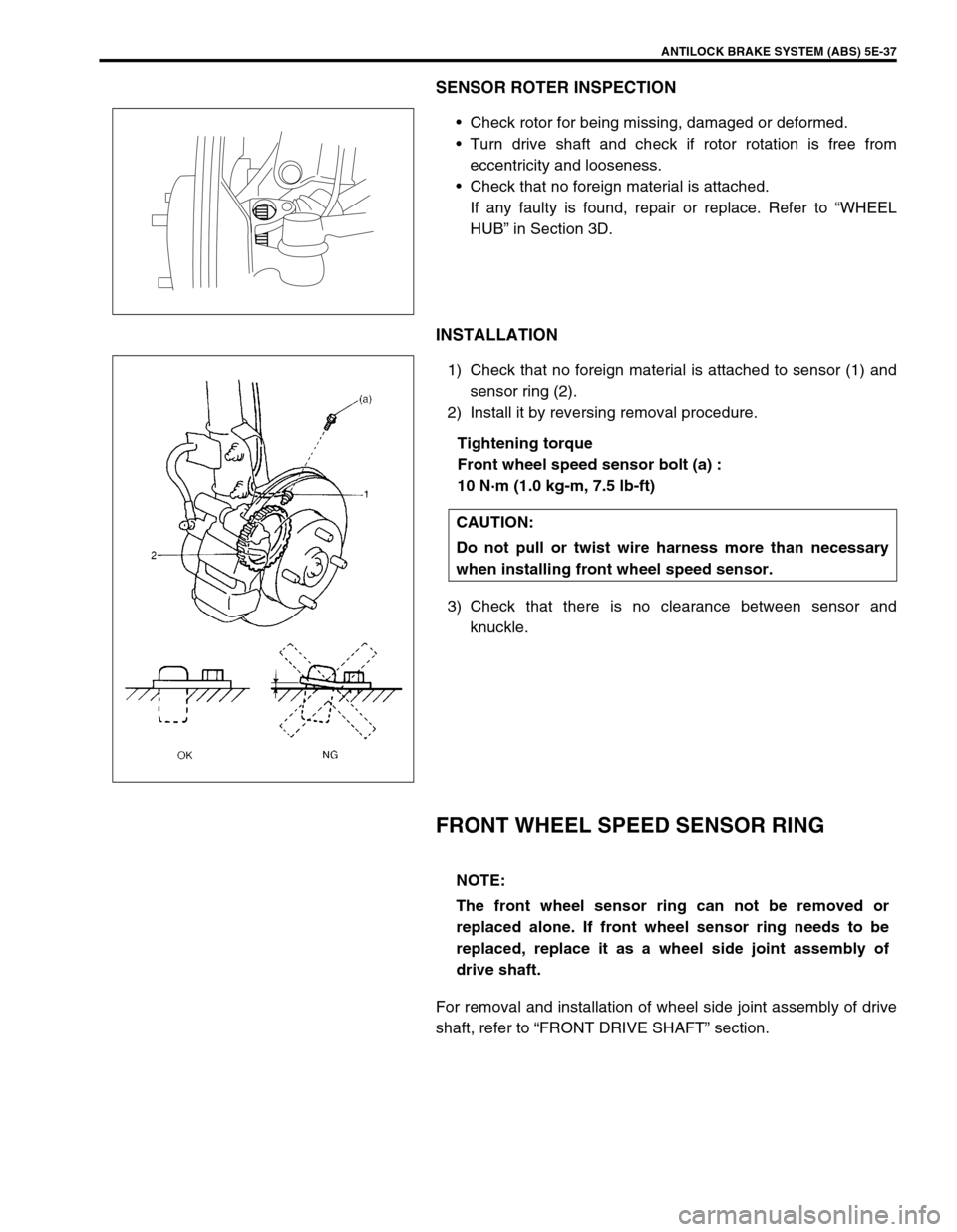
ANTILOCK BRAKE SYSTEM (ABS) 5E-37
SENSOR ROTER INSPECTION
Check rotor for being missing, damaged or deformed.
Turn drive shaft and check if rotor rotation is free from
eccentricity and looseness.
Check that no foreign material is attached.
If any faulty is found, repair or replace. Refer to “WHEEL
HUB” in Section 3D.
INSTALLATION
1) Check that no foreign material is attached to sensor (1) and
sensor ring (2).
2) Install it by reversing removal procedure.
Tightening torque
Front wheel speed sensor bolt (a) :
10 N·m (1.0 kg-m, 7.5 lb-ft)
3) Check that there is no clearance between sensor and
knuckle.
FRONT WHEEL SPEED SENSOR RING
For removal and installation of wheel side joint assembly of drive
shaft, refer to “FRONT DRIVE SHAFT” section.
CAUTION:
Do not pull or twist wire harness more than necessary
when installing front wheel speed sensor.
NOTE:
The front wheel sensor ring can not be removed or
replaced alone. If front wheel sensor ring needs to be
replaced, replace it as a wheel side joint assembly of
drive shaft.
Page 365 of 698
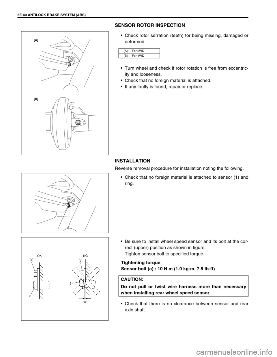
5E-40 ANTILOCK BRAKE SYSTEM (ABS)
SENSOR ROTOR INSPECTION
Check rotor serration (teeth) for being missing, damaged or
deformed.
Turn wheel and check if rotor rotation is free from eccentric-
ity and looseness.
Check that no foreign material is attached.
If any faulty is found, repair or replace.
INSTALLATION
Reverse removal procedure for installation noting the following.
Check that no foreign material is attached to sensor (1) and
ring.
Be sure to install wheel speed sensor and its bolt at the cor-
rect (upper) position as shown in figure.
Tighten sensor bolt to specified torque.
Tightening torque
Sensor bolt (a) : 10 N·m (1.0 kg-m, 7.5 lb-ft)
Check that there is no clearance between sensor and rear
axle shaft.
[A] : For 2WD
[B] : For 4WD
[B] [A]
1
CAUTION:
Do not pull or twist wire harness more than necessary
when installing rear wheel speed sensor.
Page 366 of 698
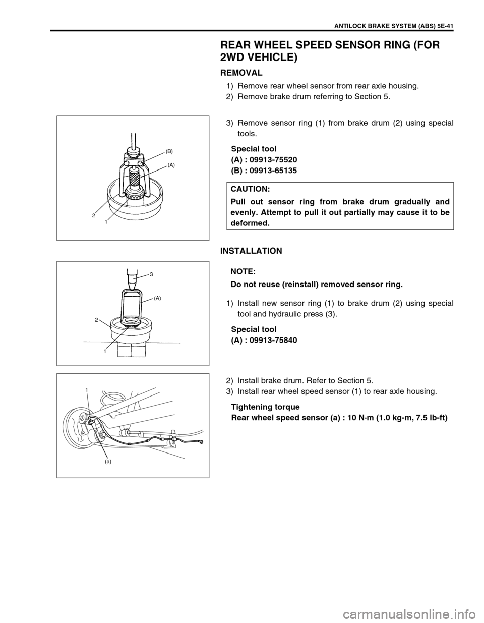
ANTILOCK BRAKE SYSTEM (ABS) 5E-41
REAR WHEEL SPEED SENSOR RING (FOR
2WD VEHICLE)
REMOVAL
1) Remove rear wheel sensor from rear axle housing.
2) Remove brake drum referring to Section 5.
3) Remove sensor ring (1) from brake drum (2) using special
tools.
Special tool
(A) : 09913-75520
(B) : 09913-65135
INSTALLATION
1) Install new sensor ring (1) to brake drum (2) using special
tool and hydraulic press (3).
Special tool
(A) : 09913-75840
2) Install brake drum. Refer to Section 5.
3) Install rear wheel speed sensor (1) to rear axle housing.
Tightening torque
Rear wheel speed sensor (a) : 10 N·m (1.0 kg-m, 7.5 lb-ft) CAUTION:
Pull out sensor ring from brake drum gradually and
evenly. Attempt to pull it out partially may cause it to be
deformed.
NOTE:
Do not reuse (reinstall) removed sensor ring.
1
(a)
Page 367 of 698
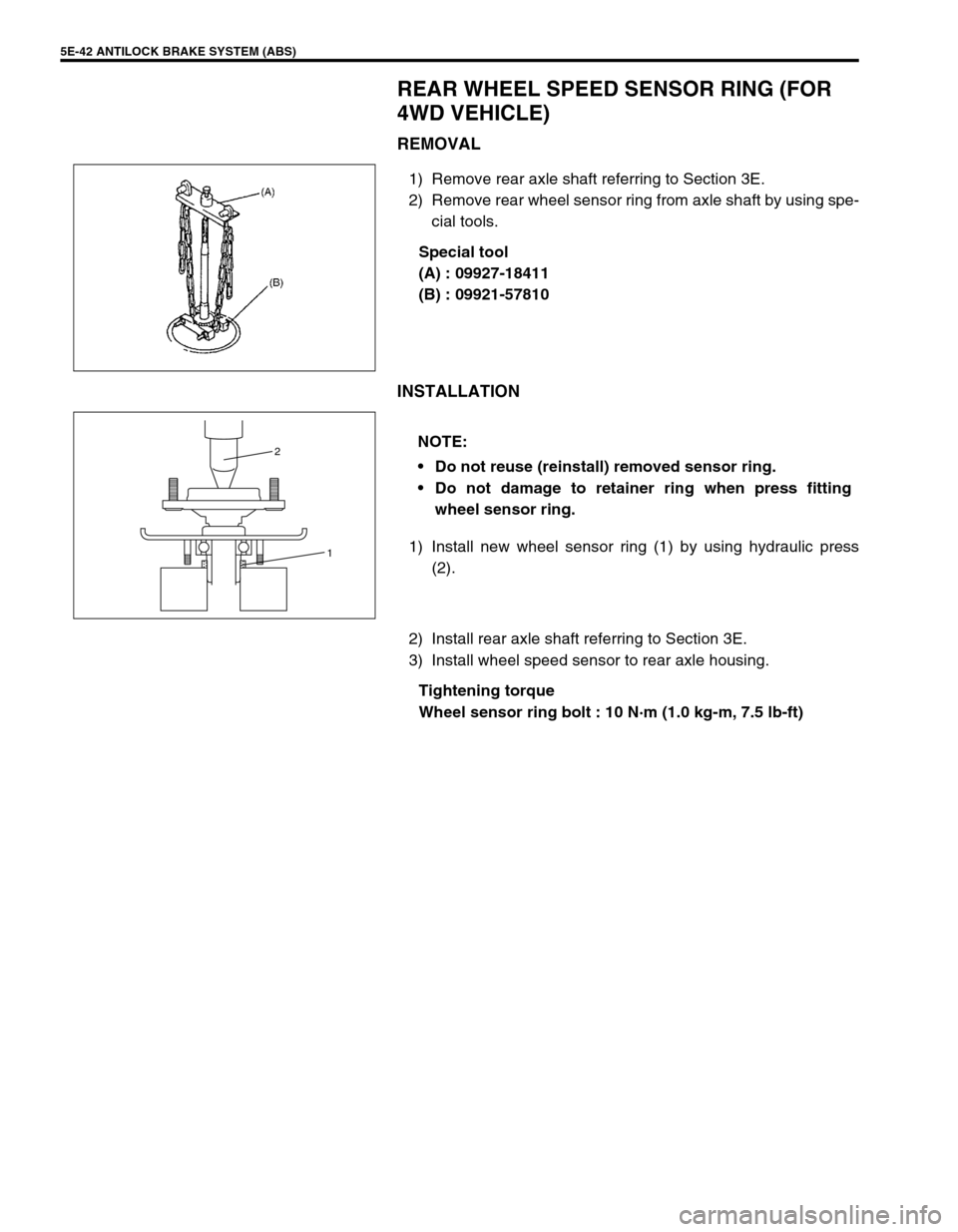
5E-42 ANTILOCK BRAKE SYSTEM (ABS)
REAR WHEEL SPEED SENSOR RING (FOR
4WD VEHICLE)
REMOVAL
1) Remove rear axle shaft referring to Section 3E.
2) Remove rear wheel sensor ring from axle shaft by using spe-
cial tools.
Special tool
(A) : 09927-18411
(B) : 09921-57810
INSTALLATION
1) Install new wheel sensor ring (1) by using hydraulic press
(2).
2) Install rear axle shaft referring to Section 3E.
3) Install wheel speed sensor to rear axle housing.
Tightening torque
Wheel sensor ring bolt : 10 N·m (1.0 kg-m, 7.5 lb-ft)
NOTE:
Do not reuse (reinstall) removed sensor ring.
Do not damage to retainer ring when press fitting
wheel sensor ring.
1 2
Page 374 of 698
ENGINE GENERAL INFORMATION AND DIAGNOSIS 6-5
PRECAUTION ON FUEL SYSTEM SERVICE
Work must be done with no smoking, in a well-ventilated
area and away from any open flames.
As fuel feed line (between fuel pump and fuel delivery pipe)
is still under high fuel pressure even after engine was
stopped, loosening or disconnecting fuel feed line directly
may cause dangerous spout of fuel to occur where loosened
or disconnected.
Before loosening or disconnecting fuel feed line, make sure
to release fuel pressure according to “FUEL PRESSURE
RELIEF PROCEDURE”. A small amount of fuel may be
released after the fuel line is disconnected. In order to
reduce the chance of personal injury, cover the fitting to be
disconnected with a shop cloth. Put that cloth in an approved
container when disconnection is completed.
Never run engine with fuel pump relay disconnected when
engine and exhaust system are hot.
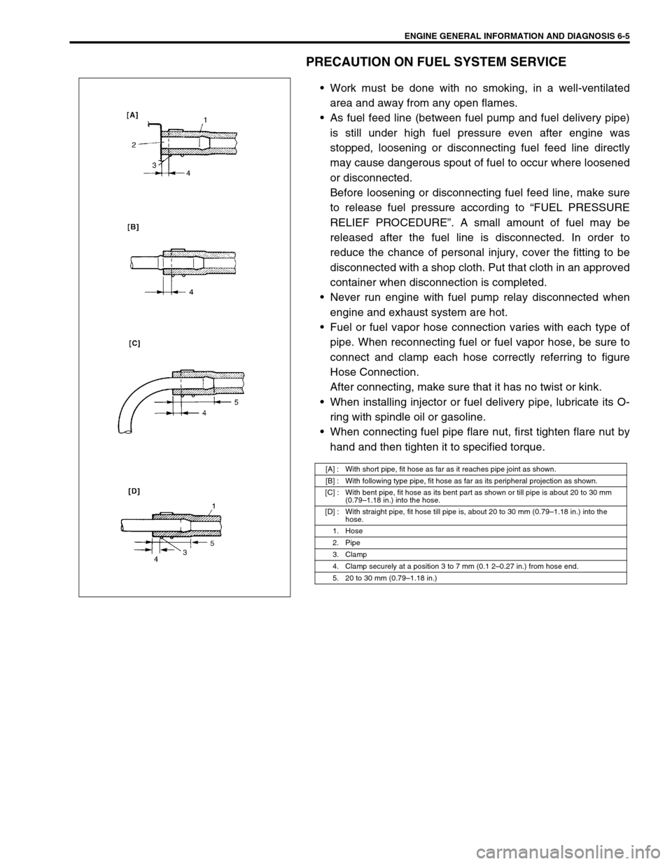
Fuel or fuel vapor hose connection varies with each type of
pipe. When reconnecting fuel or fuel vapor hose, be sure to
connect and clamp each hose correctly referring to figure
Hose Connection.
After connecting, make sure that it has no twist or kink.
When installing injector or fuel delivery pipe, lubricate its O-
ring with spindle oil or gasoline.
When connecting fuel pipe flare nut, first tighten flare nut by
hand and then tighten it to specified torque.
[A] : With short pipe, fit hose as far as it reaches pipe joint as shown.
[B] : With following type pipe, fit hose as far as its peripheral projection as shown.
[C] : With bent pipe, fit hose as its bent part as shown or till pipe is about 20 to 30 mm
(0.79–1.18 in.) into the hose.
[D] : With straight pipe, fit hose till pipe is, about 20 to 30 mm (0.79–1.18 in.) into the
hose.
1. Hose
2. Pipe
3. Clamp
4. Clamp securely at a position 3 to 7 mm (0.1 2–0.27 in.) from hose end.
5. 20 to 30 mm (0.79–1.18 in.)