Torque SUZUKI SWIFT 2000 1.G RG413 Service Manual PDF
[x] Cancel search | Manufacturer: SUZUKI, Model Year: 2000, Model line: SWIFT, Model: SUZUKI SWIFT 2000 1.GPages: 698, PDF Size: 16.01 MB
Page 232 of 698
REAR SUSPENSION 3E-19
15) Upon completion of all jobs, depress brake pedal with about
30 kg (66 Ibs) load three to five times so as to obtain proper
drum-to-shoe clearance.
Adjust parking brake cable. Refer to Section 5.
16) Install console box.
17) Lower hoist and bounce vehicle up and down several times
to stabilize suspension.
Be sure that vehicle is off hoist and in non loaded condition.
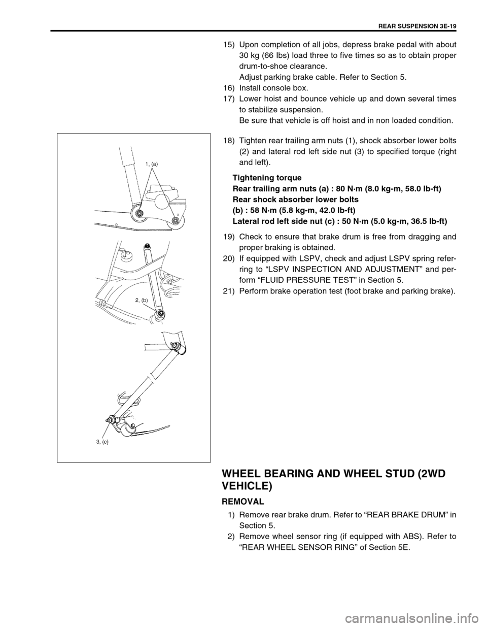
18) Tighten rear trailing arm nuts (1), shock absorber lower bolts
(2) and lateral rod left side nut (3) to specified torque (right
and left).
Tightening torque
Rear trailing arm nuts (a) : 80 N·m (8.0 kg-m, 58.0 lb-ft)
Rear shock absorber lower bolts
(b) : 58 N·m (5.8 kg-m, 42.0 lb-ft)
Lateral rod left side nut (c) : 50 N·m (5.0 kg-m, 36.5 lb-ft)
19) Check to ensure that brake drum is free from dragging and
proper braking is obtained.
20) If equipped with LSPV, check and adjust LSPV spring refer-
ring to “LSPV INSPECTION AND ADJUSTMENT” and per-
form “FLUID PRESSURE TEST” in Section 5.
21) Perform brake operation test (foot brake and parking brake).
WHEEL BEARING AND WHEEL STUD (2WD
VEHICLE)
REMOVAL
1) Remove rear brake drum. Refer to “REAR BRAKE DRUM” in
Section 5.
2) Remove wheel sensor ring (if equipped with ABS). Refer to
“REAR WHEEL SENSOR RING” of Section 5E.
Page 237 of 698
3E-24 REAR SUSPENSION
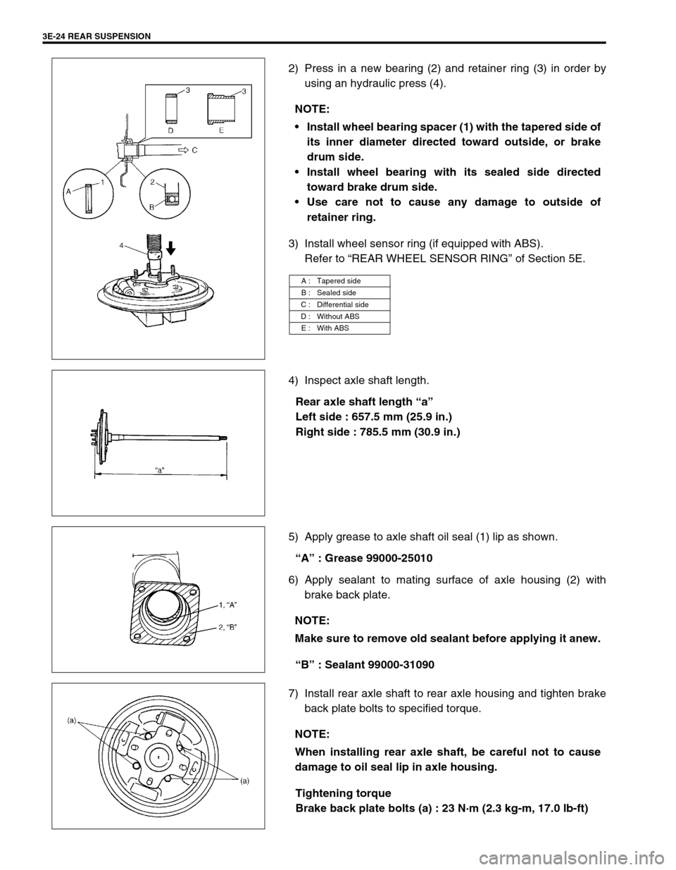
2) Press in a new bearing (2) and retainer ring (3) in order by
using an hydraulic press (4).
3) Install wheel sensor ring (if equipped with ABS).
Refer to “REAR WHEEL SENSOR RING” of Section 5E.
4) Inspect axle shaft length.
Rear axle shaft length “a”
Left side : 657.5 mm (25.9 in.)
Right side : 785.5 mm (30.9 in.)
5) Apply grease to axle shaft oil seal (1) lip as shown.
“A” : Grease 99000-25010
6) Apply sealant to mating surface of axle housing (2) with
brake back plate.
“B” : Sealant 99000-31090
7) Install rear axle shaft to rear axle housing and tighten brake
back plate bolts to specified torque.
Tightening torque
Brake back plate bolts (a) : 23 N·m (2.3 kg-m, 17.0 lb-ft) NOTE:
Install wheel bearing spacer (1) with the tapered side of
its inner diameter directed toward outside, or brake
drum side.
Install wheel bearing with its sealed side directed
toward brake drum side.
Use care not to cause any damage to outside of
retainer ring.
A : Tapered side
B : Sealed side
C : Differential side
D : Without ABS
E : With ABS
NOTE:
Make sure to remove old sealant before applying it anew.
NOTE:
When installing rear axle shaft, be careful not to cause
damage to oil seal lip in axle housing.
Page 238 of 698
REAR SUSPENSION 3E-25
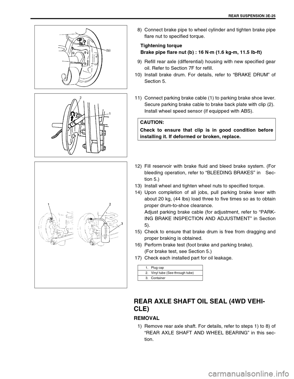
8) Connect brake pipe to wheel cylinder and tighten brake pipe
flare nut to specified torque.
Tightening torque
Brake pipe flare nut (b) : 16 N·m (1.6 kg-m, 11.5 lb-ft)
9) Refill rear axle (differential) housing with new specified gear
oil. Refer to Section 7F for refill.
10) Install brake drum. For details, refer to “BRAKE DRUM” of
Section 5.
11) Connect parking brake cable (1) to parking brake shoe lever.
Secure parking brake cable to brake back plate with clip (2).
Install wheel speed sensor (if equipped with ABS).
12) Fill reservoir with brake fluid and bleed brake system. (For
bleeding operation, refer to “BLEEDING BRAKES” in Sec-
tion 5.)
13) Install wheel and tighten wheel nuts to specified torque.
14) Upon completion of all jobs, pull parking brake lever with
about 20 kg, (44 lbs) load three to five times so as to obtain
proper drum-to-shoe clearance.
Adjust parking brake cable (for adjustment, refer to “PARK-
ING BRAKE INSPECTION AND ADJUSTMENT” in Section
5).
15) Check to ensure that brake drum is free from dragging and
proper braking is obtained.
16) Perform brake test (foot brake and parking brake).
(For brake test, see Section 5.)
17) Check each installed part for oil leakage.
REAR AXLE SHAFT OIL SEAL (4WD VEHI-
CLE)
REMOVAL
1) Remove rear axle shaft. For details, refer to steps 1) to 8) of
“REAR AXLE SHAFT AND WHEEL BEARING” in this sec-
tion.
CAUTION:
Check to ensure that clip is in good condition before
installing it. If deformed or broken, replace.
1. Plug cap
2. Vinyl tube (See-through tube)
3. Container
Page 242 of 698
REAR SUSPENSION 3E-29
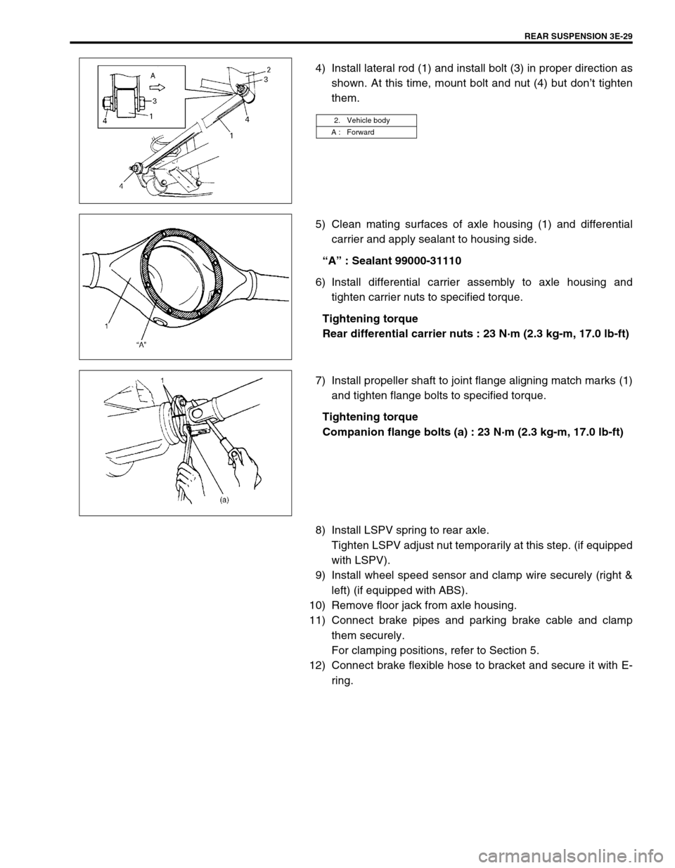
4) Install lateral rod (1) and install bolt (3) in proper direction as
shown. At this time, mount bolt and nut (4) but don’t tighten
them.
5) Clean mating surfaces of axle housing (1) and differential
carrier and apply sealant to housing side.
“A” : Sealant 99000-31110
6) Install differential carrier assembly to axle housing and
tighten carrier nuts to specified torque.
Tightening torque
Rear differential carrier nuts : 23 N·m (2.3 kg-m, 17.0 lb-ft)
7) Install propeller shaft to joint flange aligning match marks (1)
and tighten flange bolts to specified torque.
Tightening torque
Companion flange bolts (a) : 23 N·m (2.3 kg-m, 17.0 lb-ft)
8) Install LSPV spring to rear axle.
Tighten LSPV adjust nut temporarily at this step. (if equipped
with LSPV).
9) Install wheel speed sensor and clamp wire securely (right &
left) (if equipped with ABS).
10) Remove floor jack from axle housing.
11) Connect brake pipes and parking brake cable and clamp
them securely.
For clamping positions, refer to Section 5.
12) Connect brake flexible hose to bracket and secure it with E-
ring.
2. Vehicle body
A : Forward
Page 243 of 698
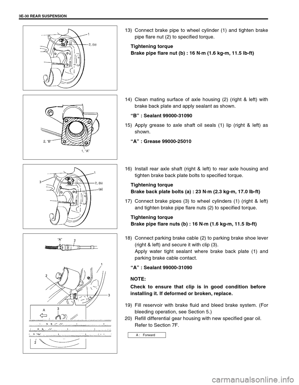
3E-30 REAR SUSPENSION
13) Connect brake pipe to wheel cylinder (1) and tighten brake
pipe flare nut (2) to specified torque.
Tightening torque
Brake pipe flare nut (b) : 16 N·m (1.6 kg-m, 11.5 lb-ft)
14) Clean mating surface of axle housing (2) (right & left) with
brake back plate and apply sealant as shown.
“B” : Sealant 99000-31090
15) Apply grease to axle shaft oil seals (1) lip (right & left) as
shown.
“A” : Grease 99000-25010
16) Install rear axle shaft (right & left) to rear axle housing and
tighten brake back plate bolts to specified torque.
Tightening torque
Brake back plate bolts (a) : 23 N·m (2.3 kg-m, 17.0 lb-ft)
17) Connect brake pipes (3) to wheel cylinders (1) (right & left)
and tighten brake pipe flare nuts (2) to specified torque.
Tightening torque
Brake pipe flare nuts (b) : 16 N·m (1.6 kg-m, 11.5 lb-ft)
18) Connect parking brake cable (2) to parking brake shoe lever
(right & left) and secure it with clip (3).
Apply water tight sealant where brake back plate (1) and
parking brake cable contact.
“A” : Sealant 99000-31090
19) Fill reservoir with brake fluid and bleed brake system. (For
bleeding operation, see Section 5.)
20) Refill differential gear housing with new specified gear oil.
Refer to Section 7F.
NOTE:
Check to ensure that clip is in good condition before
installing it. If deformed or broken, replace.
A : Forward
Page 244 of 698
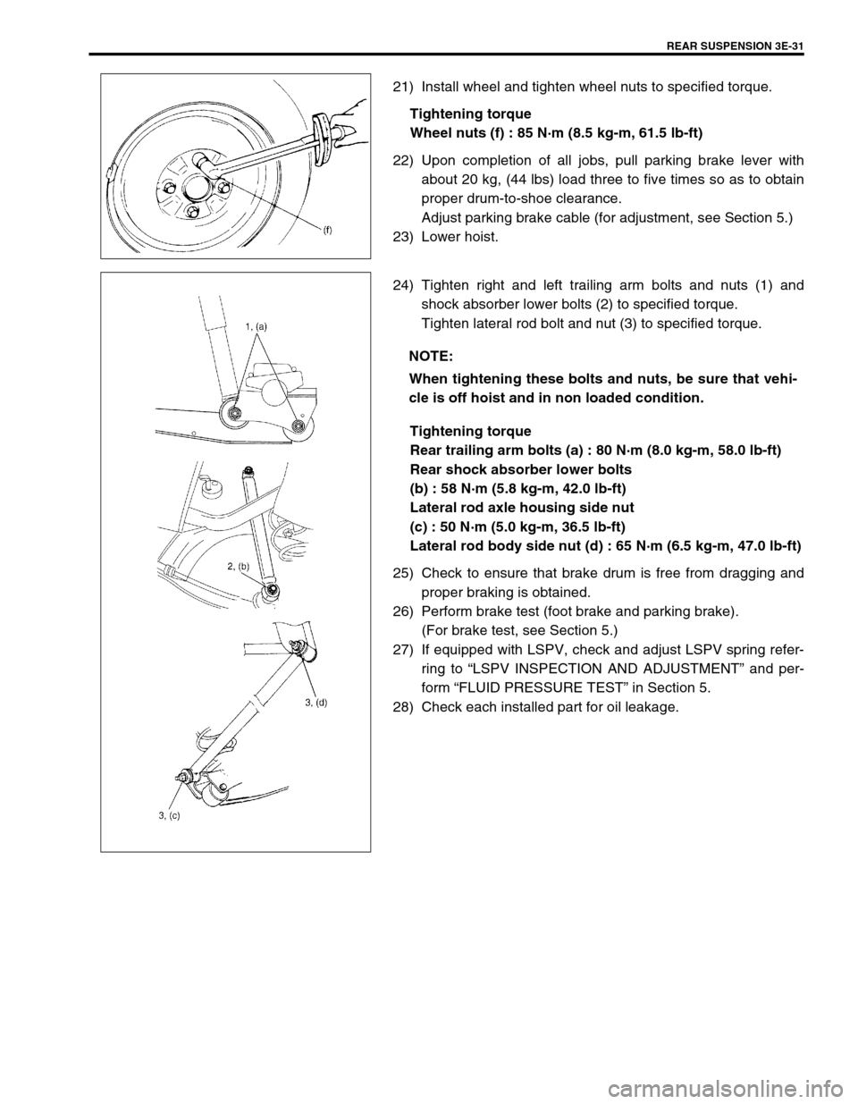
REAR SUSPENSION 3E-31
21) Install wheel and tighten wheel nuts to specified torque.
Tightening torque
Wheel nuts (f) : 85 N·m (8.5 kg-m, 61.5 lb-ft)
22) Upon completion of all jobs, pull parking brake lever with
about 20 kg, (44 lbs) load three to five times so as to obtain
proper drum-to-shoe clearance.
Adjust parking brake cable (for adjustment, see Section 5.)
23) Lower hoist.
24) Tighten right and left trailing arm bolts and nuts (1) and
shock absorber lower bolts (2) to specified torque.
Tighten lateral rod bolt and nut (3) to specified torque.
Tightening torque
Rear trailing arm bolts (a) : 80 N·m (8.0 kg-m, 58.0 lb-ft)
Rear shock absorber lower bolts
(b) : 58 N·m (5.8 kg-m, 42.0 lb-ft)
Lateral rod axle housing side nut
(c) : 50 N·m (5.0 kg-m, 36.5 lb-ft)
Lateral rod body side nut (d) : 65 N·m (6.5 kg-m, 47.0 lb-ft)
25) Check to ensure that brake drum is free from dragging and
proper braking is obtained.
26) Perform brake test (foot brake and parking brake).
(For brake test, see Section 5.)
27) If equipped with LSPV, check and adjust LSPV spring refer-
ring to “LSPV INSPECTION AND ADJUSTMENT” and per-
form “FLUID PRESSURE TEST” in Section 5.
28) Check each installed part for oil leakage.
NOTE:
When tightening these bolts and nuts, be sure that vehi-
cle is off hoist and in non loaded condition.
Page 246 of 698
WHEELS AND TIRES 3F-1
6F1
6F2
6G
3F
8A
8B
8C
8D
8E
9
10
10A
10B
SECTION 3F
WHEELS AND TIRES
CONTENTS
GENERAL DESCRIPTION ............................... 3F-2
TIRES ............................................................ 3F-2
WHEELS ....................................................... 3F-2
REPLACEMENT TIRES ................................ 3F-2
REPLACEMENT WHEELS ........................... 3F-2
HOW TO MEASURE WHEEL RUNOUT... 3F-3
METRIC LUG NUTS AND WHEEL
STUDS ...................................................... 3F-3
DIAGNOSIS ...................................................... 3F-3
DIAGNOSIS TABLE ...................................... 3F-3
BALANCING WHEELS ................................. 3F-3
GENERAL BALANCE PROCEDURES ......... 3F-4
OFF-VEHICLE BALANCING ..................... 3F-4
ON-VEHICLE BALANCING....................... 3F-4MAINTENANCE AND MINOR
ADJUSTMENTS ............................................... 3F-5
WHEEL MAINTENANCE .............................. 3F-5
WHEEL ATTACHING STUDS .................. 3F-5
MATCHED TIRES AND WHEELS ............ 3F-5
TIRE MAINTENANCE................................... 3F-5
TIRE PLACARD ........................................ 3F-5
INFLATION OF TIRES .............................. 3F-6
TIRE ROTATION ...................................... 3F-6
ON-VEHICLE SERVICE ................................... 3F-7
WHEEL ......................................................... 3F-7
TIRE .............................................................. 3F-8
MOUNTING AND DISMOUNTING ........... 3F-8
REPAIR ..................................................... 3F-8
NOTE:
All wheel fasteners are important attaching parts in that they could affect the performance of vital
parts and systems, and/or could result in major repair expense. They must be replaced with one of the
same part number or with an equivalent part if replacement becomes necessary. Do not use a replace-
ment part of lesser quality or substitute design. Torque values must be used as specified during reas-
sembly to assure proper retention of all parts.
There is to be no welding as it may result in extensive damage and weakening of the metal.
Page 252 of 698
WHEELS AND TIRES 3F-7
ON-VEHICLE SERVICE
WHEEL
REMOVAL
1) Loosen wheel nuts by approximately 180° (half a rotation).
2) Hoist vehicle.
3) Remove wheel.
INSTALLATION
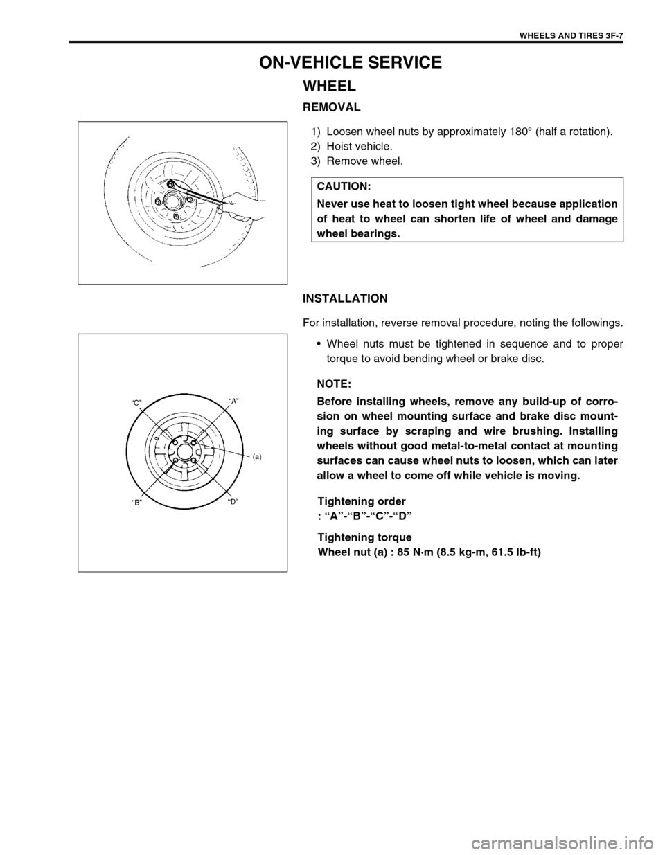
For installation, reverse removal procedure, noting the followings.
Wheel nuts must be tightened in sequence and to proper
torque to avoid bending wheel or brake disc.
Tightening order
: “A”-“B”-“C”-“D”
Tightening torque
Wheel nut (a) : 85 N·m (8.5 kg-m, 61.5 lb-ft) CAUTION:
Never use heat to loosen tight wheel because application
of heat to wheel can shorten life of wheel and damage
wheel bearings.
NOTE:
Before installing wheels, remove any build-up of corro-
sion on wheel mounting surface and brake disc mount-
ing surface by scraping and wire brushing. Installing
wheels without good metal-to-metal contact at mounting
surfaces can cause wheel nuts to loosen, which can later
allow a wheel to come off while vehicle is moving.
Page 254 of 698
FRONT DRIVE SHAFT 4A-1
6F1
6F2
6G
6H
6K
7A
7A1
7B1
7C1
7D
7E
7F
4A
8C
8D
8E
9
10
10A
10B
SECTION 4A
FRONT DRIVE SHAFT
CONTENTS
GENERAL DESCRIPTION .............................. 4A-2
COMPONENT .............................................. 4A-2
DIAGNOSIS ..................................................... 4A-2
DIAGNOSIS TABLE ..................................... 4A-2
DRIVE SHAFT BOOT CHECK ..................... 4A-2ON-VEHICLE SERVICE .................................. 4A-3
DRIVE SHAFT ASSEMBLY ......................... 4A-4
TIGHTENING TORQUE SPECIFICATION.... 4A-16
REQUIRED SERVICE MATERIAL................ 4A-16
SPECIAL TOOL ............................................ 4A-16
Page 256 of 698
FRONT DRIVE SHAFT 4A-3
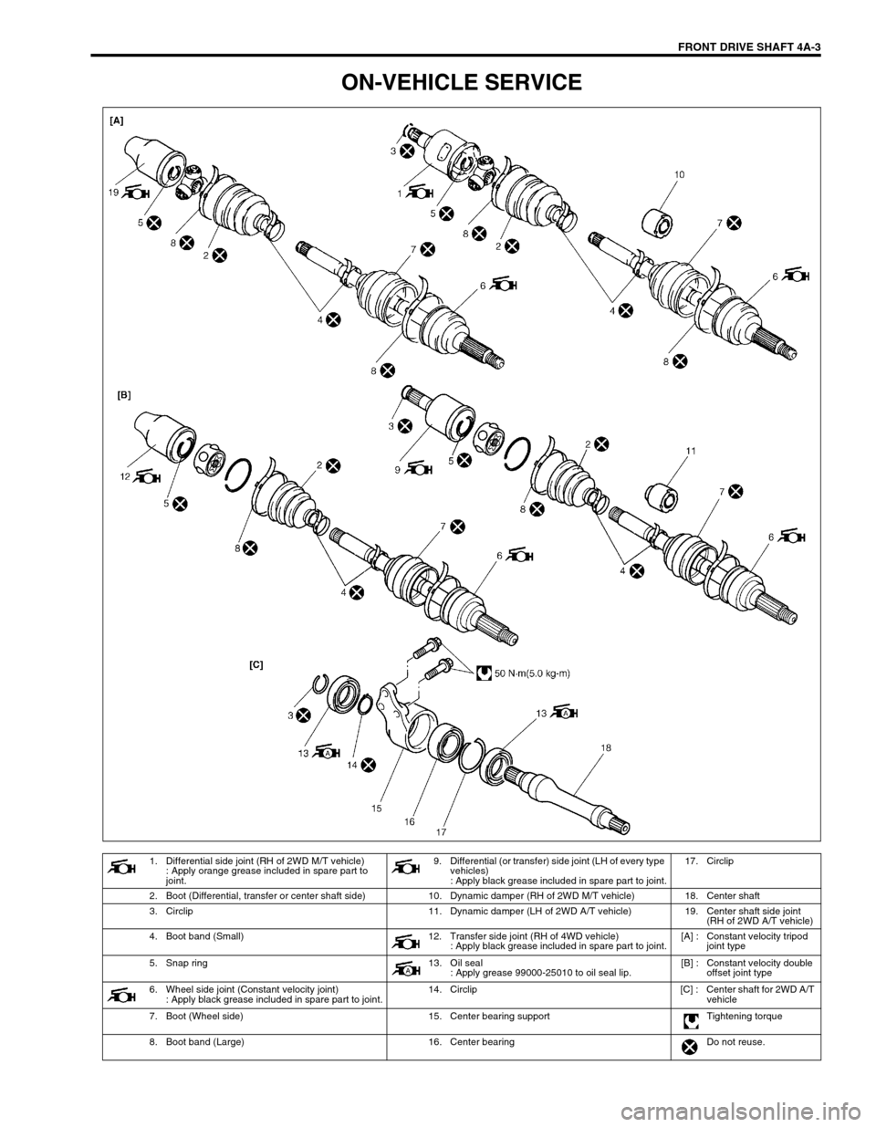
ON-VEHICLE SERVICE
1. Differential side joint (RH of 2WD M/T vehicle)
: Apply orange grease included in spare part to
joint.9. Differential (or transfer) side joint (LH of every type
vehicles)
: Apply black grease included in spare part to joint.17. Circlip
2. Boot (Differential, transfer or center shaft side) 10. Dynamic damper (RH of 2WD M/T vehicle) 18. Center shaft
3. Circlip 11. Dynamic damper (LH of 2WD A/T vehicle) 19. Center shaft side joint
(RH of 2WD A/T vehicle)
4. Boot band (Small) 12. Transfer side joint (RH of 4WD vehicle)
: Apply black grease included in spare part to joint.[A] : Constant velocity tripod
joint type
5. Snap ring 13. Oil seal
: Apply grease 99000-25010 to oil seal lip.[B] : Constant velocity double
offset joint type
6. Wheel side joint (Constant velocity joint)
: Apply black grease included in spare part to joint.14. Circlip [C] : Center shaft for 2WD A/T
vehicle
7. Boot (Wheel side) 15. Center bearing support Tightening torque
8. Boot band (Large) 16. Center bearing Do not reuse.