Torque SUZUKI SWIFT 2000 1.G RG413 Service Workshop Manual
[x] Cancel search | Manufacturer: SUZUKI, Model Year: 2000, Model line: SWIFT, Model: SUZUKI SWIFT 2000 1.GPages: 698, PDF Size: 16.01 MB
Page 306 of 698
BRAKES 5-33
BRAKE BACK PLATE (FOR 4WD VEHICLE)
REMOVAL AND INSTALLATION
Refer to “REAR AXLE SHAFT AND WHEEL BEARING (4WD VEHICLE)” in Section 3E.
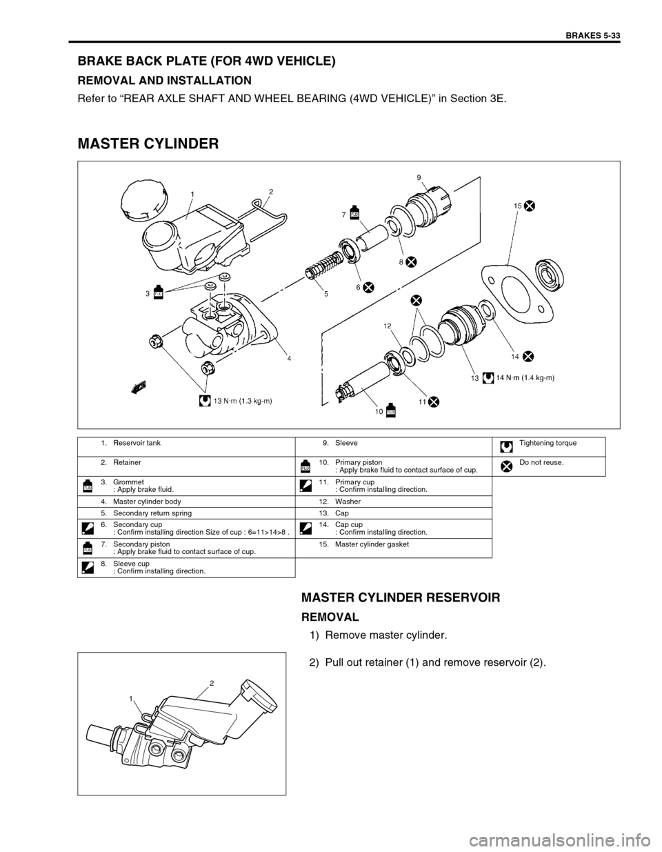
MASTER CYLINDER
MASTER CYLINDER RESERVOIR
REMOVAL
1) Remove master cylinder.
2) Pull out retainer (1) and remove reservoir (2).
1. Reservoir tank 9. Sleeve Tightening torque
2. Retainer 10. Primary piston
: Apply brake fluid to contact surface of cup.Do not reuse.
3. Grommet
: Apply brake fluid.11. Primary cup
: Confirm installing direction.
4. Master cylinder body 12. Washer
5. Secondary return spring 13. Cap
6. Secondary cup
: Confirm installing direction Size of cup : 6=11>14>8 .14. Cap cup
: Confirm installing direction.
7. Secondary piston
: Apply brake fluid to contact surface of cup.15. Master cylinder gasket
8. Sleeve cup
: Confirm installing direction.
2
1
Page 310 of 698
BRAKES 5-37
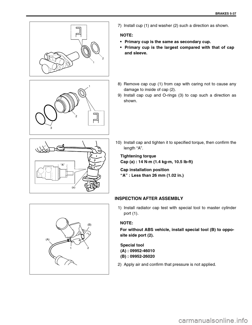
7) Install cup (1) and washer (2) such a direction as shown.
8) Remove cap cup (1) from cap with caring not to cause any
damage to inside of cap (2).
9) Install cap cup and O-rings (3) to cap such a direction as
shown.
10) Install cap and tighten it to specified torque, then confirm the
length “A”.
Tightening torque
Cap (a) : 14 N·m (1.4 kg-m, 10.5 lb-ft)
Cap installation position
“A” : Less than 26 mm (1.02 in.)
INSPECTION AFTER ASSEMBLY
1) Install radiator cap test with special tool to master cylinder
port (1).
Special tool
(A) : 09952-46010
(B) : 09952-26020
2) Apply air and confirm that pressure is not applied.NOTE:
Primary cup is the same as secondary cup.
Primary cup is the largest compared with that of cap
and sleeve.
NOTE:
For without ABS vehicle, install special tool (B) to oppo-
site side port (2).
1(B)
2 (A)
Page 311 of 698
5-38 BRAKES
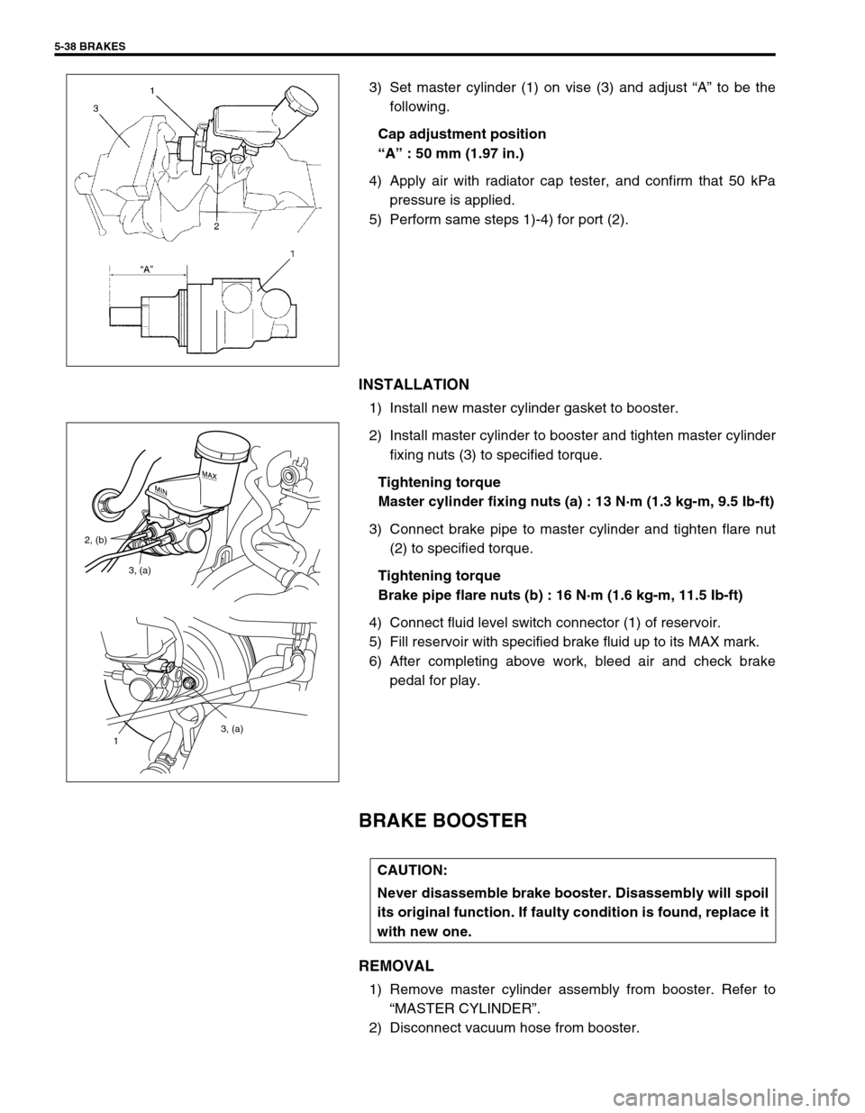
3) Set master cylinder (1) on vise (3) and adjust “A” to be the
following.
Cap adjustment position
“A” : 50 mm (1.97 in.)
4) Apply air with radiator cap tester, and confirm that 50 kPa
pressure is applied.
5) Perform same steps 1)-4) for port (2).
INSTALLATION
1) Install new master cylinder gasket to booster.
2) Install master cylinder to booster and tighten master cylinder
fixing nuts (3) to specified torque.
Tightening torque
Master cylinder fixing nuts (a) : 13 N·m (1.3 kg-m, 9.5 Ib-ft)
3) Connect brake pipe to master cylinder and tighten flare nut
(2) to specified torque.
Tightening torque
Brake pipe flare nuts (b) : 16 N·m (1.6 kg-m, 11.5 Ib-ft)
4) Connect fluid level switch connector (1) of reservoir.
5) Fill reservoir with specified brake fluid up to its MAX mark.
6) After completing above work, bleed air and check brake
pedal for play.
BRAKE BOOSTER
REMOVAL
1) Remove master cylinder assembly from booster. Refer to
“MASTER CYLINDER”.
2) Disconnect vacuum hose from booster.
3, (a)
1
3, (a) 2, (b)
CAUTION:
Never disassemble brake booster. Disassembly will spoil
its original function. If faulty condition is found, replace it
with new one.
Page 312 of 698
BRAKES 5-39
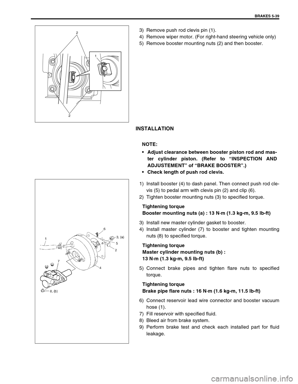
3) Remove push rod clevis pin (1).
4) Remove wiper motor. (For right-hand steering vehicle only)
5) Remove booster mounting nuts (2) and then booster.
INSTALLATION
1) Install booster (4) to dash panel. Then connect push rod cle-
vis (5) to pedal arm with clevis pin (2) and clip (6).
2) Tighten booster mounting nuts (3) to specified torque.
Tightening torque
Booster mounting nuts (a) : 13 N·m (1.3 kg-m, 9.5 lb-ft)
3) Install new master cylinder gasket to booster.
4) Install master cylinder (7) to booster and tighten mounting
nuts (8) to specified torque.
Tightening torque
Master cylinder mounting nuts (b) :
13 N·m (1.3 kg-m, 9.5 lb-ft)
5) Connect brake pipes and tighten flare nuts to specified
torque.
Tightening torque
Brake pipe flare nuts : 16 N·m (1.6 kg-m, 11.5 lb-ft)
6) Connect reservoir lead wire connector and booster vacuum
hose (1).
7) Fill reservoir with specified fluid.
8) Bleed air from brake system.
9) Perform brake test and check each installed part for fluid
leakage.
1
2
2
NOTE:
Adjust clearance between booster piston rod and mas-
ter cylinder piston. (Refer to “INSPECTION AND
ADJUSTEMENT” of “BRAKE BOOSTER”.)
Check length of push rod clevis.
Page 313 of 698

5-40 BRAKES
INSPECTION AND ADJUSTMENT
Installation Position Of Push Rod
If push rod clevis (1) has been removed, adjust distance between
booster installation surface (without including packing) and the
center of clevis pin hole to standard value “a” and tighten nut (2)
to specified torque.
Distance “a” between center of booster clevis pin hole
and booster surface
Standard : 97 - 98 mm (3.82 - 3.86 in.)
Tightening torque
Clevis pin lock nut (a) : 19 N·m (1.9 kg-m, 14.0 lb-ft)
Clearance Between Booster Piston Rod And Master Cylin-
der Piston
The length of booster piston rod (1) is adjusted to provide speci-
fied clearance “a” between piston rod (1) end and master cylinder
piston (2).
Before measuring clearance, push piston rod several times
so as to make sure reaction disc is in place.
Keep inside of booster at atmospheric pressure for measure-
ment.
Measure length “a” of piston rod, i.e. distance between piston rod
and mating surface of booster-to-master cylinder.
Length “a” of piston rod
: 30.3 - 30.5 mm (1.193 - 1.200 in.)
If measurement is out of specification, adjust piston rod by turning
adjusting screw of piston rod.
Special tool
(B) : 09952-16020
NOTE:
Remove gasket from booster, if equipped.
Page 315 of 698
![SUZUKI SWIFT 2000 1.G RG413 Service Workshop Manual 5-42 BRAKES
For vehicle with ABS
T : Top side [A] : For left-hand steering vehicle 4. From ABS hydraulic unit to right front brake
F : Front side [B] : For right-hand steering vehicle 5. ABS hydrauli SUZUKI SWIFT 2000 1.G RG413 Service Workshop Manual 5-42 BRAKES
For vehicle with ABS
T : Top side [A] : For left-hand steering vehicle 4. From ABS hydraulic unit to right front brake
F : Front side [B] : For right-hand steering vehicle 5. ABS hydrauli](/img/20/7606/w960_7606-314.png)
5-42 BRAKES
For vehicle with ABS
T : Top side [A] : For left-hand steering vehicle 4. From ABS hydraulic unit to right front brake
F : Front side [B] : For right-hand steering vehicle 5. ABS hydraulic unit
R : Right side 1. From master cylinder primary to ABS hydraulic unit 6. Master cylinder
A : View A 2. From master cylinder secondary to ABS hydraulic unit 7. Front brake hose
a-f: Clamp 3. From ABS hydraulic unit to left front brake Tightening torque
Page 316 of 698
![SUZUKI SWIFT 2000 1.G RG413 Service Workshop Manual BRAKES 5-43
For vehicle without ABS
T : Top side 1. From master cylinder primary to left front brake [A] : For left-hand steering vehicle
F : Front side 2. From master cylinder secondary to right fro SUZUKI SWIFT 2000 1.G RG413 Service Workshop Manual BRAKES 5-43
For vehicle without ABS
T : Top side 1. From master cylinder primary to left front brake [A] : For left-hand steering vehicle
F : Front side 2. From master cylinder secondary to right fro](/img/20/7606/w960_7606-315.png)
BRAKES 5-43
For vehicle without ABS
T : Top side 1. From master cylinder primary to left front brake [A] : For left-hand steering vehicle
F : Front side 2. From master cylinder secondary to right front brake [B] : For right-hand steering vehicle
R : Right side 3. Master cylinder a-g: Clamp
A : View A 4. Front brake hose Tightening torque
Page 318 of 698
![SUZUKI SWIFT 2000 1.G RG413 Service Workshop Manual BRAKES 5-45
T : Top side 1. 4 way joint [A] : with ABS
F : Front side 2. LSPV assembly [B] : without ABS
R : Right side 3. P valve [C] : with LSPV
L : Left side 4. Rear brake hose Tightening torque SUZUKI SWIFT 2000 1.G RG413 Service Workshop Manual BRAKES 5-45
T : Top side 1. 4 way joint [A] : with ABS
F : Front side 2. LSPV assembly [B] : without ABS
R : Right side 3. P valve [C] : with LSPV
L : Left side 4. Rear brake hose Tightening torque](/img/20/7606/w960_7606-317.png)
BRAKES 5-45
T : Top side 1. 4 way joint [A] : with ABS
F : Front side 2. LSPV assembly [B] : without ABS
R : Right side 3. P valve [C] : with LSPV
L : Left side 4. Rear brake hose Tightening torque
B : View B a-g: Clamp
Page 319 of 698
5-46 BRAKES
PARKING BRAKE CABLE
REMOVAL
1) Raise, suitably support vehicle and remove wheel.
2) Remove parking brake cable.
INSTALLATION
Install it by reversing removal procedure, noting the following points.
Install clamps properly referring to figure below.
Tighten bolts and nuts to specified torque.
Adjust parking brake cable. (Refer to “PARKING BRAKE INSPECTION AND ADJUSTMENT”.)
Check brake drum for dragging and brake system for proper performance. After removing vehicle from hoist,
brake test should be performed.
Page 320 of 698

BRAKES 5-47
T : Top side 3. Inner cable end a : View A f : View F
F : Front side 4. Spring b : View B Tightening torque
R : Rear side 5. Adjusting nut c : View C
1. Cable
: Apply water tight sealant (99000-31090)6. Clip d : View D
2. Parking brake shoe lever 7. Parking brake lever e : View E