SUZUKI SWIFT 2000 1.G Transmission Service Workshop Manual
Manufacturer: SUZUKI, Model Year: 2000, Model line: SWIFT, Model: SUZUKI SWIFT 2000 1.GPages: 447, PDF Size: 10.54 MB
Page 261 of 447
BODY ELECTRICAL SYSTEM 8-17
FUEL LEVEL SENSOR (GAUGE UNIT)
REMOVAL
Remove fuel pump assembly (1) referring to Section 6C.
INSTALLATION
Install fuel pump assembly (1) referring to Section 6C.
INSPECTION
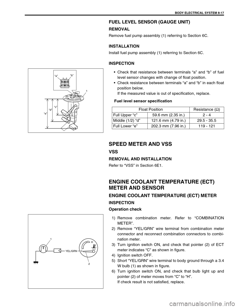
Check that resistance between terminals “a” and “b” of fuel
level sensor changes with change of float position.
Check resistance between terminals “a” and “b” in each float
position below.
If the measured value is out of specification, replace.
Fuel level sensor specification
SPEED METER AND VSS
VSS
REMOVAL AND INSTALLATION
Refer to “VSS” in Section 6E1.
ENGINE COOLANT TEMPERATURE (ECT)
METER AND SENSOR
ENGINE COOLANT TEMPERATURE (ECT) METER
INSPECTION
Operation check
1) Remove combination meter. Refer to “COMBINATION
METER”.
2) Remove “YEL/GRN” wire terminal from combination meter
connector and reconnect combination connectors to combi-
nation meter.
3) Turn ignition switch ON, and check that pointer (2) of ECT
meter indicates “C” as shown in figure.
4) Ignition switch OFF.
5) Short “YEL/GRN” wire terminal to body ground through a 3.4
W bulb (1) as shown in figure.
6) Turn ignition switch ON, and check that bulb light up and
pointer (2) of meter moves from “C” to “H”.
If check result is not satisfied, replace.Float Position Resistance (Ω
)
Full Upper “c”59.6 mm (2.35 in.) 2 - 4
Middle (1/2) “d”121.6 mm (4.79 in.) 29.5 - 35.5
Full Lower “e”202.3 mm (7.96 in.) 119 - 121
“a”“b”
1
“c”
“d”
“e”
YEL/GRNC
H1
2
Page 262 of 447
8-18 BODY ELECTRICAL SYSTEM
ECT SENSOR
REMOVAL, INSTALLATION AND INSPECTION
Refer to “ECT SENSOR” in Section 6E1.
OIL PRESSURE WARNING LIGHT
OIL PRESSURE SWITCH
ON-VEHICLE INSPECTION
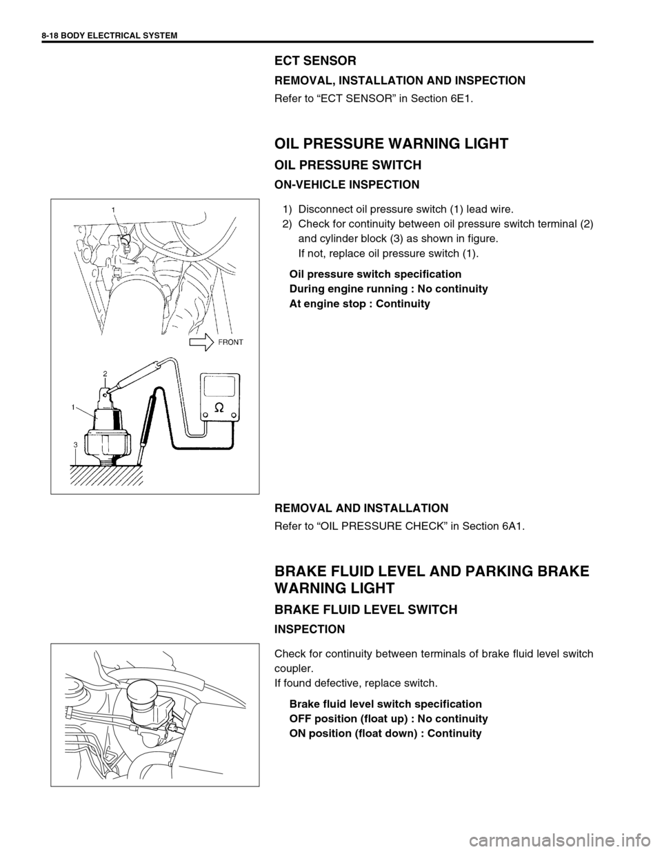
1) Disconnect oil pressure switch (1) lead wire.
2) Check for continuity between oil pressure switch terminal (2)
and cylinder block (3) as shown in figure.
If not, replace oil pressure switch (1).
Oil pressure switch specification
During engine running : No continuity
At engine stop : Continuity
REMOVAL AND INSTALLATION
Refer to “OIL PRESSURE CHECK” in Section 6A1.
BRAKE FLUID LEVEL AND PARKING BRAKE
WARNING LIGHT
BRAKE FLUID LEVEL SWITCH
INSPECTION
Check for continuity between terminals of brake fluid level switch
coupler.
If found defective, replace switch.
Brake fluid level switch specification
OFF position (float up) : No continuity
ON position (float down) : Continuity
Page 263 of 447
BODY ELECTRICAL SYSTEM 8-19
PARKING BRAKE SWITCH
INSPECTION
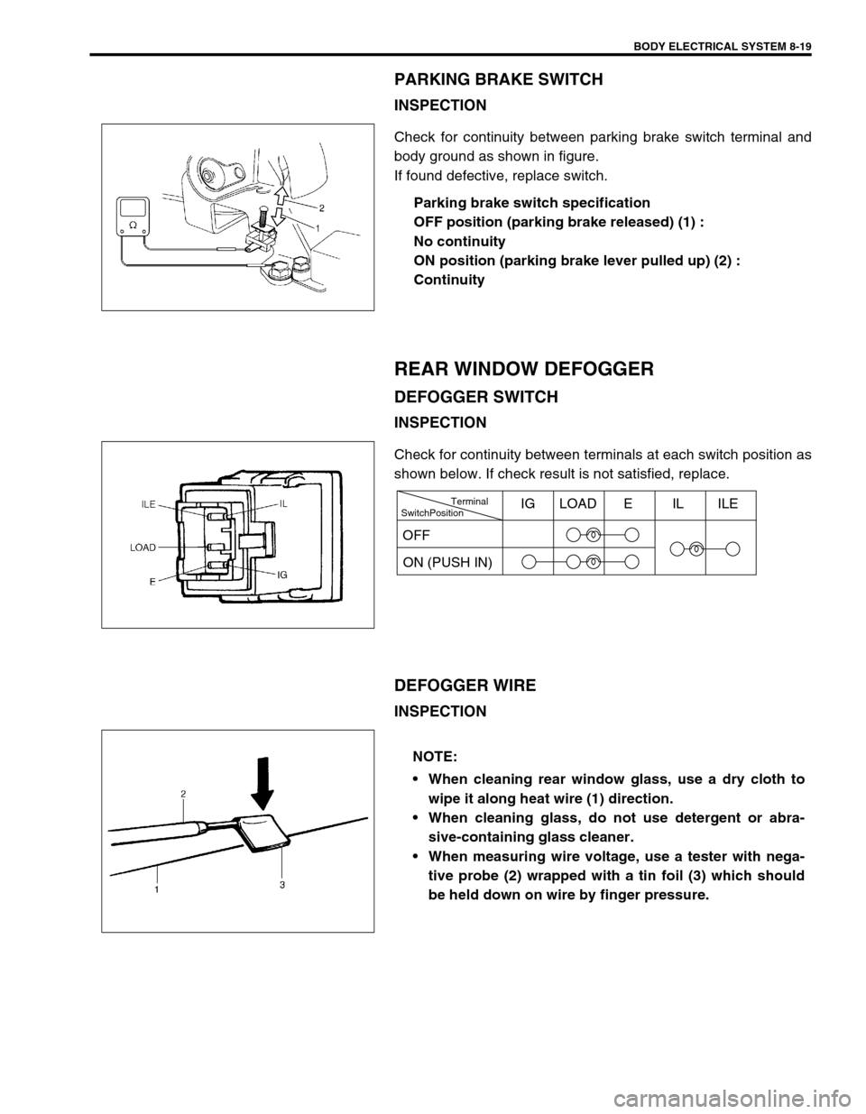
Check for continuity between parking brake switch terminal and
body ground as shown in figure.
If found defective, replace switch.
Parking brake switch specification
OFF position (parking brake released) (1) :
No continuity
ON position (parking brake lever pulled up) (2) :
Continuity
REAR WINDOW DEFOGGER
DEFOGGER SWITCH
INSPECTION
Check for continuity between terminals at each switch position as
shown below. If check result is not satisfied, replace.
DEFOGGER WIRE
INSPECTION
SwitchPositionTerminal
ON (PUSH IN)IG LOAD E IL ILE
OFF
NOTE:
When cleaning rear window glass, use a dry cloth to
wipe it along heat wire (1) direction.
When cleaning glass, do not use detergent or abra-
sive-containing glass cleaner.
When measuring wire voltage, use a tester with nega-
tive probe (2) wrapped with a tin foil (3) which should
be held down on wire by finger pressure.
Page 264 of 447
8-20 BODY ELECTRICAL SYSTEM
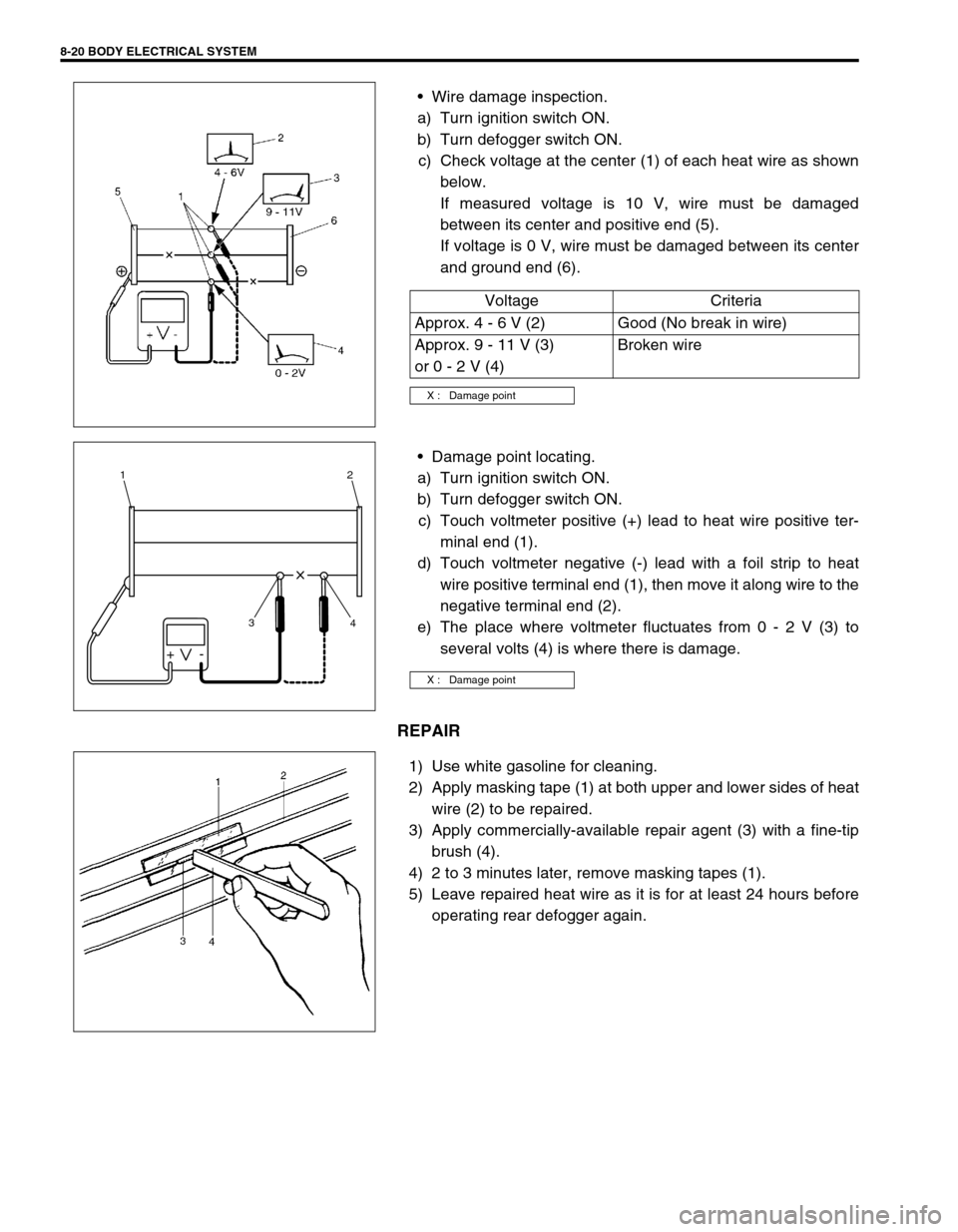
Wire damage inspection.
a) Turn ignition switch ON.
b) Turn defogger switch ON.
c) Check voltage at the center (1) of each heat wire as shown
below.
If measured voltage is 10 V, wire must be damaged
between its center and positive end (5).
If voltage is 0 V, wire must be damaged between its center
and ground end (6).
Damage point locating.
a) Turn ignition switch ON.
b) Turn defogger switch ON.
c) Touch voltmeter positive (+) lead to heat wire positive ter-
minal end (1).
d) Touch voltmeter negative (-) lead with a foil strip to heat
wire positive terminal end (1), then move it along wire to the
negative terminal end (2).
e) The place where voltmeter fluctuates from 0 - 2 V (3) to
several volts (4) is where there is damage.
REPAIR
1) Use white gasoline for cleaning.
2) Apply masking tape (1) at both upper and lower sides of heat
wire (2) to be repaired.
3) Apply commercially-available repair agent (3) with a fine-tip
brush (4).
4) 2 to 3 minutes later, remove masking tapes (1).
5) Leave repaired heat wire as it is for at least 24 hours before
operating rear defogger again.Voltage Criteria
Approx. 4 - 6 V (2) Good (No break in wire)
Approx. 9 - 11 V (3)
or 0 - 2 V (4)Broken wire
X : Damage point
X : Damage point
+-
3 12
4
Page 265 of 447
![SUZUKI SWIFT 2000 1.G Transmission Service Workshop Manual BODY ELECTRICAL SYSTEM 8-21
WIPERS AND WASHERS
COMPONENTS
FRONT WIPER AND WASHER SWITCH
REMOVAL AND INSTALLATION
Refer to “CONTACT COIL AND COMBINATION SWITCH
ASSEMBLY” in Section 3C.
[A] : RH ste SUZUKI SWIFT 2000 1.G Transmission Service Workshop Manual BODY ELECTRICAL SYSTEM 8-21
WIPERS AND WASHERS
COMPONENTS
FRONT WIPER AND WASHER SWITCH
REMOVAL AND INSTALLATION
Refer to “CONTACT COIL AND COMBINATION SWITCH
ASSEMBLY” in Section 3C.
[A] : RH ste](/img/20/7605/w960_7605-264.png)
BODY ELECTRICAL SYSTEM 8-21
WIPERS AND WASHERS
COMPONENTS
FRONT WIPER AND WASHER SWITCH
REMOVAL AND INSTALLATION
Refer to “CONTACT COIL AND COMBINATION SWITCH
ASSEMBLY” in Section 3C.
[A] : RH steering vehicle 3. Wiper motor 7. Washer hose
[B] : LH steering vehicle 4. Washer pump (for front washer) 8. Washer nozzle
1. Wiper blade 5. Washer pump (for rear washer) 9. Wiper link
2. Wiper arm 6. Washer tank
Page 266 of 447
8-22 BODY ELECTRICAL SYSTEM
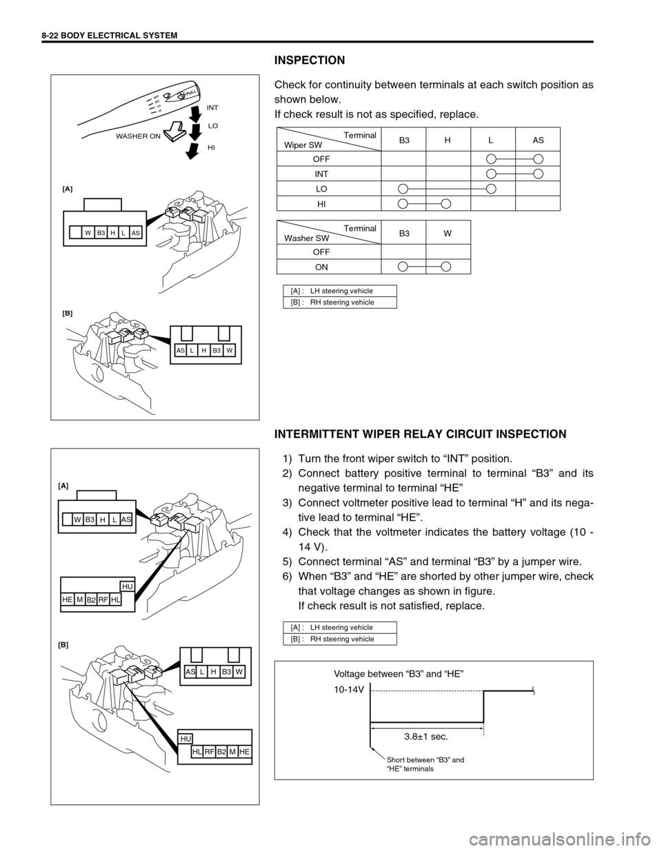
INSPECTION
Check for continuity between terminals at each switch position as
shown below.
If check result is not as specified, replace.
INTERMITTENT WIPER RELAY CIRCUIT INSPECTION
1) Turn the front wiper switch to “INT” position.
2) Connect battery positive terminal to terminal “B3” and its
negative terminal to terminal “HE”
3) Connect voltmeter positive lead to terminal “H” and its nega-
tive lead to terminal “HE”.
4) Check that the voltmeter indicates the battery voltage (10 -
14 V).
5) Connect terminal “AS” and terminal “B3” by a jumper wire.
6) When “B3” and “HE” are shorted by other jumper wire, check
that voltage changes as shown in figure.
If check result is not satisfied, replace.
[A] : LH steering vehicle
[B] : RH steering vehicle
INT
WASHER ONLO
[A]
[B]HI
AS AS
L L
H H
B3 B3
W W
HI LO INT OFF
PULL
Terminal
Wiper SW
OFF
INT
LOB3 H L AS
HI
Terminal
Washer SW
OFF
ONB3 W
[A] : LH steering vehicle
[B] : RH steering vehicle
AS L H B3 W
HU
HL RF B2 M HE
AS
L
H B3
W
HU
HL RF
B2 M HE [A]
[B]
10-14V Voltage between “B3” and “HE”
3.8±1 sec.
Short between “B3” and
“HE” terminals
Page 267 of 447
BODY ELECTRICAL SYSTEM 8-23
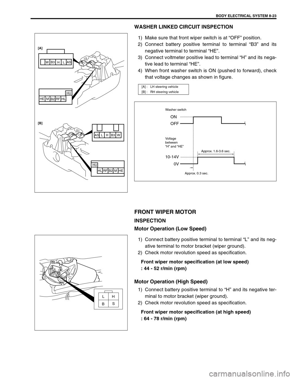
WASHER LINKED CIRCUIT INSPECTION
1) Make sure that front wiper switch is at “OFF” position.
2) Connect battery positive terminal to terminal “B3” and its
negative terminal to terminal “HE”.
3) Connect voltmeter positive lead to terminal “H” and its nega-
tive lead to terminal “HE”.
4) When front washer switch is ON (pushed to forward), check
that voltage changes as shown in figure.
FRONT WIPER MOTOR
INSPECTION
Motor Operation (Low Speed)
1) Connect battery positive terminal to terminal “L” and its neg-
ative terminal to motor bracket (wiper ground).
2) Check motor revolution speed as specification.
Front wiper motor specification (at low speed)
: 44 - 52 r/min (rpm)
Motor Operation (High Speed)
1) Connect battery positive terminal to “H” and its negative ter-
minal to motor bracket (wiper ground).
2) Check motor revolution speed as specification.
Front wiper motor specification (at high speed)
: 64 - 78 r/min (rpm)
[A] : LH steering vehicle
[B] : RH steering vehicle
AS L H B3 W
HU
HL RF B2 M HE
HU
HL RF
B2 M HE [A]
[B]
AS
L
H B3
W
10-14V
Washer switch
Voltage
between
“H” and “HE”
0V ON
OFF
Approx. 0.3 sec.Approx. 1.6-3.6 sec.
LH
S
B
Page 268 of 447
8-24 BODY ELECTRICAL SYSTEM
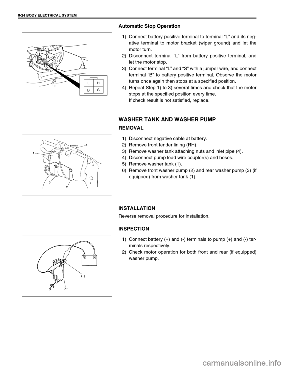
Automatic Stop Operation
1) Connect battery positive terminal to terminal “L” and its neg-
ative terminal to motor bracket (wiper ground) and let the
motor turn.
2) Disconnect terminal “L” from battery positive terminal, and
let the motor stop.
3) Connect terminal “L” and “S” with a jumper wire, and connect
terminal “B” to battery positive terminal. Observe the motor
turns once again then stops at a specified position.
4) Repeat Step 1) to 3) several times and check that the motor
stops at the specified position every time.
If check result is not satisfied, replace.
WASHER TANK AND WASHER PUMP
REMOVAL
1) Disconnect negative cable at battery.
2) Remove front fender lining (RH).
3) Remove washer tank attaching nuts and inlet pipe (4).
4) Disconnect pump lead wire coupler(s) and hoses.
5) Remove washer tank (1).
6) Remove front washer pump (2) and rear washer pump (3) (if
equipped) from washer tank (1).
INSTALLATION
Reverse removal procedure for installation.
INSPECTION
1) Connect battery (+) and (-) terminals to pump (+) and (-) ter-
minals respectively.
2) Check motor operation for both front and rear (if equipped)
washer pump.
LH
S
B
Page 269 of 447
BODY ELECTRICAL SYSTEM 8-25
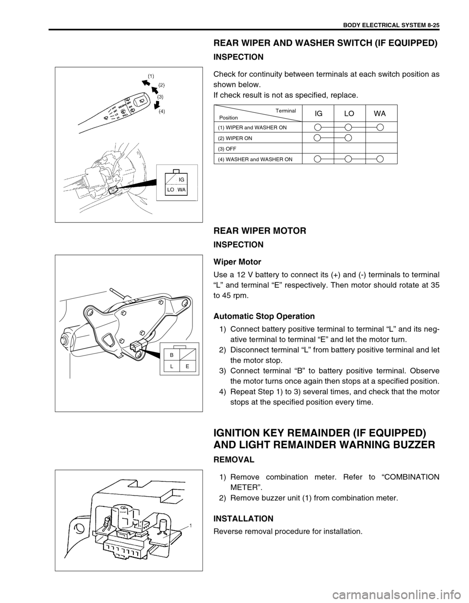
REAR WIPER AND WASHER SWITCH (IF EQUIPPED)
INSPECTION
Check for continuity between terminals at each switch position as
shown below.
If check result is not as specified, replace.
REAR WIPER MOTOR
INSPECTION
Wiper Motor
Use a 12 V battery to connect its (+) and (-) terminals to terminal
“L” and terminal “E” respectively. Then motor should rotate at 35
to 45 rpm.
Automatic Stop Operation
1) Connect battery positive terminal to terminal “L” and its neg-
ative terminal to terminal “E” and let the motor turn.
2) Disconnect terminal “L” from battery positive terminal and let
the motor stop.
3) Connect terminal “B” to battery positive terminal. Observe
the motor turns once again then stops at a specified position.
4) Repeat Step 1) to 3) several times, and check that the motor
stops at the specified position every time.
IGNITION KEY REMAINDER (IF EQUIPPED)
AND LIGHT REMAINDER WARNING BUZZER
REMOVAL
1) Remove combination meter. Refer to “COMBINATION
METER”.
2) Remove buzzer unit (1) from combination meter.
INSTALLATION
Reverse removal procedure for installation.
Terminal
Position
(1) WIPER and WASHER ON
(2) WIPER ON
(3) OFFIG LO WA
(4) WASHER and WASHER ON
B
E L
Page 270 of 447
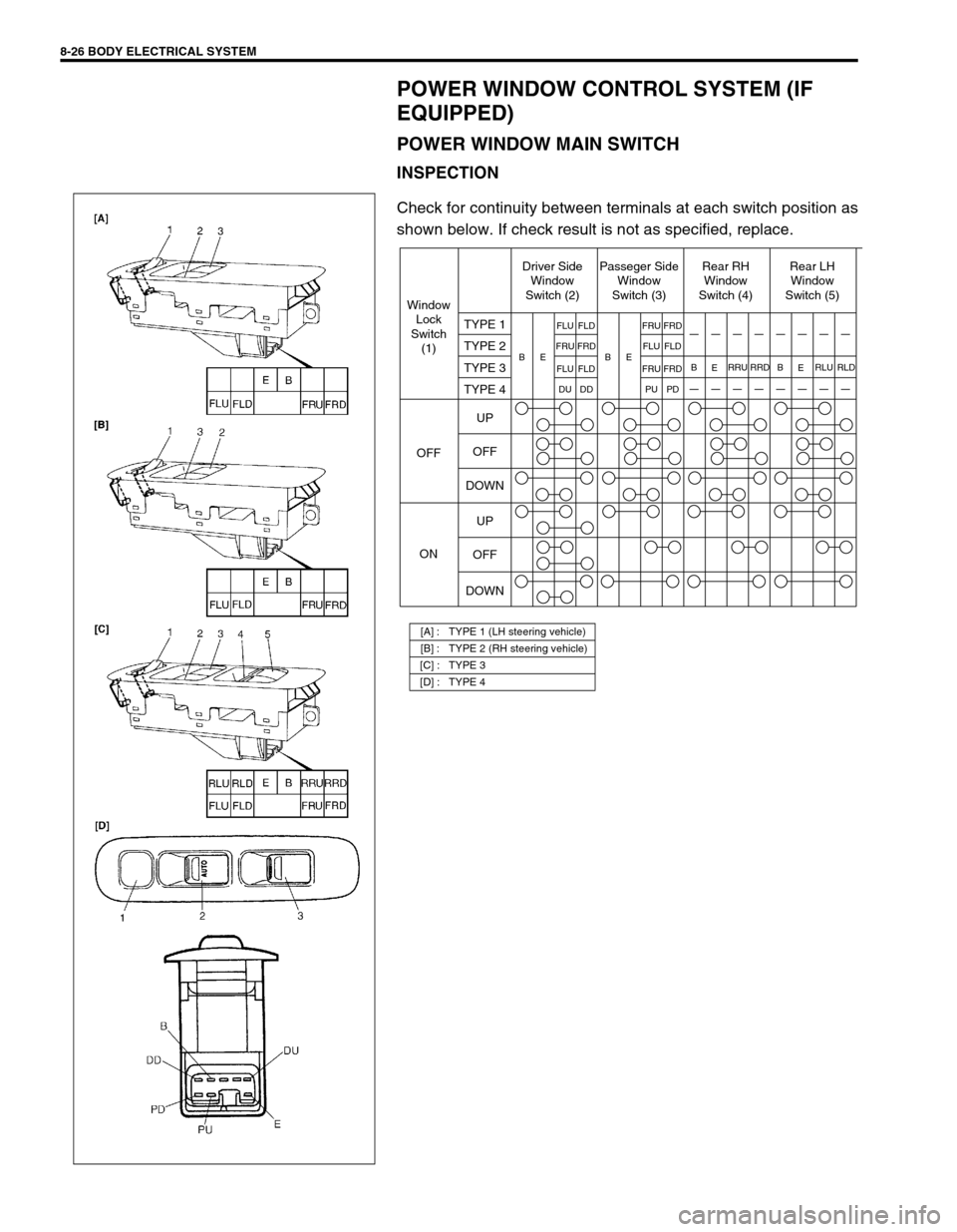
8-26 BODY ELECTRICAL SYSTEM
POWER WINDOW CONTROL SYSTEM (IF
EQUIPPED)
POWER WINDOW MAIN SWITCH
INSPECTION
Check for continuity between terminals at each switch position as
shown below. If check result is not as specified, replace.
[A] : TYPE 1 (LH steering vehicle)
[B] : TYPE 2 (RH steering vehicle)
[C] : TYPE 3
[D] : TYPE 4
Window
Lock
Switch
(1)Driver Side
Window
Switch (2)Passeger Side
Window
Switch (3)Rear RH
Window
Switch (4)Rear LH
Window
Switch (5)
OFF
ONTYPE 1
TYPE 2
TYPE 3
TYPE 4
UP
OFF
DOWN
UP
OFF
DOWN
B
B EBE
E FLU
FRU
FLU
DUFLD
FRD
FLD
DDFRU
RRU RRD B
ERLU RLD FLU
FRU
PUFRD
FLD
FRD
PD