TOYOTA AVENSIS 2005 Service Repair Manual
Manufacturer: TOYOTA, Model Year: 2005, Model line: AVENSIS, Model: TOYOTA AVENSIS 2005Pages: 5135, PDF Size: 95.28 MB
Page 1541 of 5135
I35670
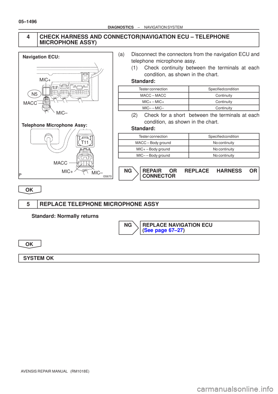
MIC+
MACC MIC±
MACC MIC+ MIC±
Navigation ECU:
Telephone Microphone Assy:
T11
N5
05±1496
±
DIAGNOSTICS NAVIGATION SYSTEM
AVENSIS REPAIR MANUAL (RM1018E)
4CHECK HARNESS AND CONNECTOR(NAVIGATION ECU ± TELEPHONE MICROPHONE ASSY)
(a)Disconnect the connectors from the navigation ECU and
telephone microphone assy.
(1)Check continuity between the terminals at eachcondition, as shown in the chart.
Standard:
Tester connectionSpecified condition
MACC ± MACCContinuity
MIC+ ± MIC+Continuity
MIC± ± MIC±Continuity
(2)Check for a short between the terminals at each condition, as shown in the chart.
Standard:
Tester connectionSpecified condition
MACC ± Body groundNo continuity
MIC+ ± Body groundNo continuity
MIC± ± Body groundNo continuity
NGREPAIR OR REPLACE HARNESS OR CONNECTOR
OK
5REPLACE TELEPHONE MICROPHONE ASSY
Standard: Normally returns NGREPLACE NAVIGATION ECU (See page 67±27)
OK
SYSTEM OK
Page 1542 of 5135
I34721
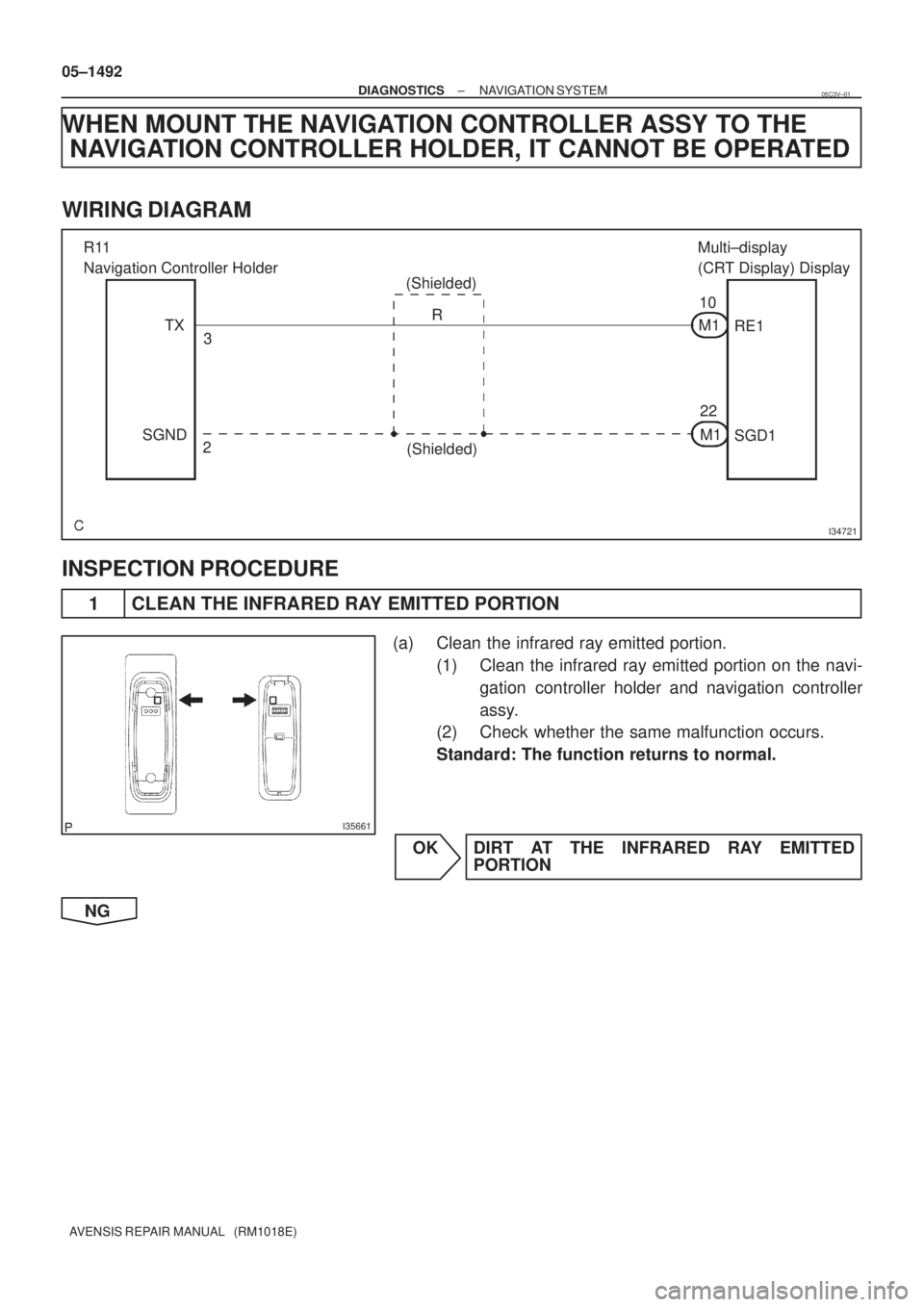
R11
Navigation Controller Holder
(Shielded)Multi±display
(CRT Display) Display
TX
SGND3
2R
(Shielded)10
22 M1
M1RE1
SGD1
I35661
05±1492
± DIAGNOSTICSNAVIGATION SYSTEM
AVENSIS REPAIR MANUAL (RM1018E)
WHEN MOUNT THE NAVIGATION CONTROLLER ASSY TO THE
NAVIGATION CONTROLLER HOLDER, IT CANNOT BE OPERATED
WIRING DIAGRAM
INSPECTION PROCEDURE
1 CLEAN THE INFRARED RAY EMITTED PORTION
(a) Clean the infrared ray emitted portion.
(1) Clean the infrared ray emitted portion on the navi-
gation controller holder and navigation controller
assy.
(2) Check whether the same malfunction occurs.
Standard: The function returns to normal.
OK DIRT AT THE INFRARED RAY EMITTED
PORTION
NG
05C3V±01
Page 1543 of 5135
I35698
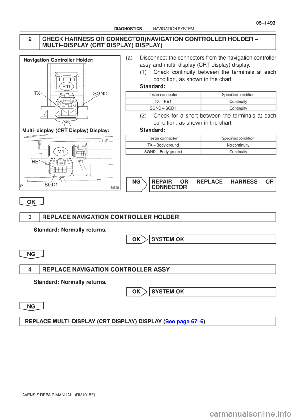
Multi±display (CRT Display) Display:Navigation Controller Holder:
R11
M1
SGND
TX
RE1 SGD1
±
DIAGNOSTICS NAVIGATION SYSTEM
05±1493
AVENSIS REPAIR MANUAL (RM1018E)
2CHECK HARNESS OR CONNECTOR(NAVIGATION CONTROLLER HOLDER ±
MULTI±DISPLAY (CRT DISPLAY) DISPLAY)
(a)Disconnect the connectors from the navigation controller
assy and multi±display (CRT display) display.
(1)Check continuity between the terminals at eachcondition, as shown in the chart.
Standard:
Tester connecterSpecified condition
TX ± RE1Continuity
SGND ± SGD1Continuity
(2)Check for a short between the terminals at each condition, as shown in the chart
Standard:
Tester connecterSpecified condition
TX ± Body groundNo continuity
SGND ± Body groundContinuity
NGREPAIR OR REPLACE HARNESS OR CONNECTOR
OK
3REPLACE NAVIGATION CONTROLLER HOLDER
Standard: Normally returns. OKSYSTEM OK
NG
4REPLACE NAVIGATION CONTROLLER ASSY
Standard: Normally returns. OKSYSTEM OK
NG
REPLACE MULTI±DISPLAY (CRT DISPLAY) DISPLAY (See page 67±6)
Page 1544 of 5135
I35660
±
DIAGNOSTICS NAVIGATION SYSTEM
05±1491
AVENSIS REPAIR MANUAL (RM1018E)
A NAVIGATION CONTROLLER ASSY DOES NOT OPERATE
INSPECTION PROCEDURE
1CHECK MALFUNCTION SYMPTOMS
(a)Check obstruction.
(1)Check that there are no obstructions between the navigation controller assy a\
nd the infrared ray
light emission portion of the multi±display (CRT display) display.
Standard: Normally returns
OKSYSTEM OK
NG
2CHECK BATTERY(NAVIGATION CONTROLLER ASSY)
(a)Check battery. (1)Check that the dry±cell battery used for the navigation controller as\
sy is not dead.
Standard: It is not dead
NGBATTERY IS DEAD
OK
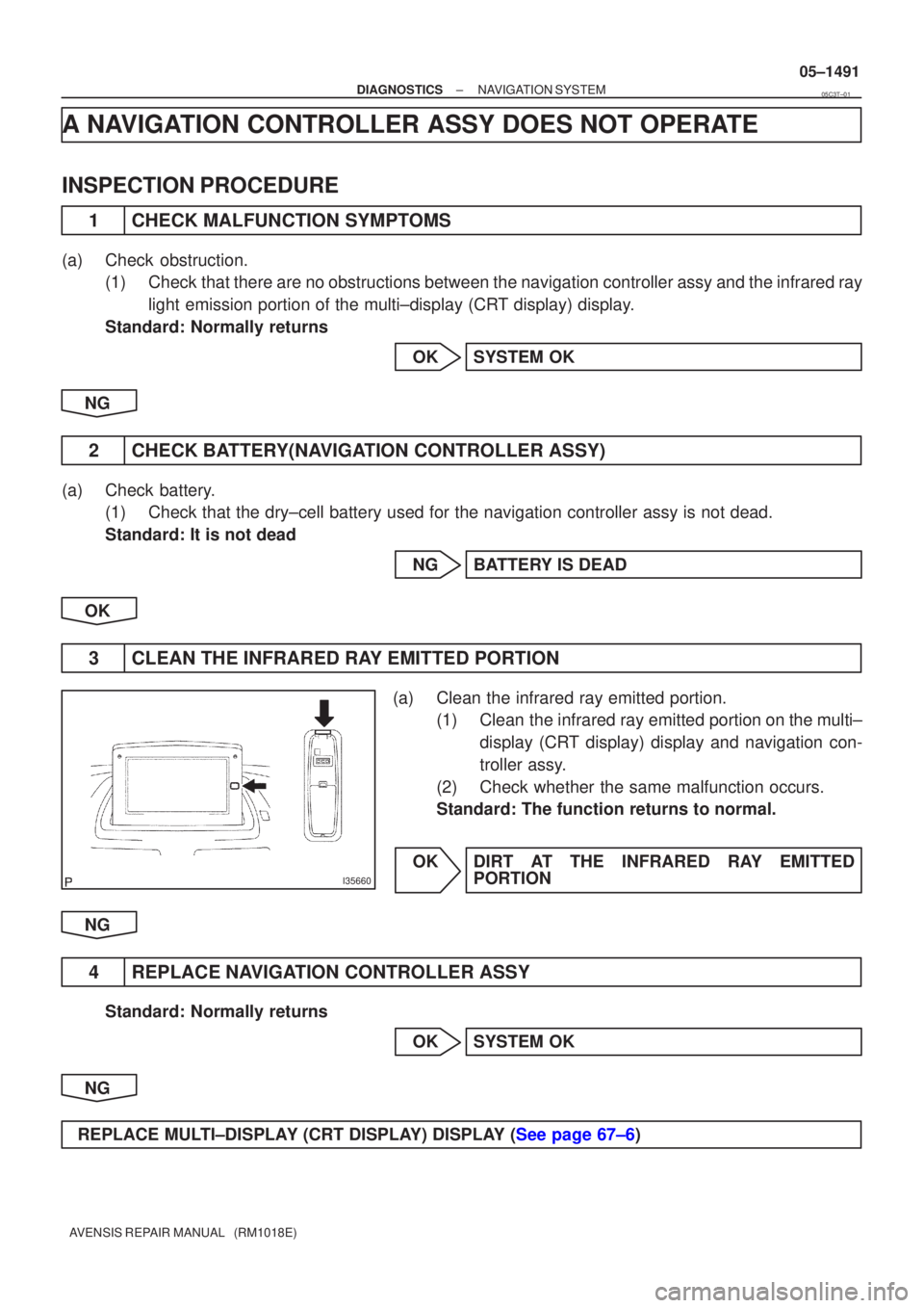
3CLEAN THE INFRARED RAY EMITTED PORTION
(a)Clean the infrared ray emitted portion. (1)Clean the infrared ray emitted portion on the multi±
display (CRT display) display and navigation con-
troller assy.
(2)Check whether the same malfunction occurs.
Standard: The function returns to normal.
OKDIRT AT THE INFRARED RAY EMITTED PORTION
NG
4REPLACE NAVIGATION CONTROLLER ASSY
Standard: Normally returns OKSYSTEM OK
NG
REPLACE MULTI±DISPLAY (CRT DISPLAY) DISPLAY (See page 67±6)
05C3T±01
Page 1545 of 5135
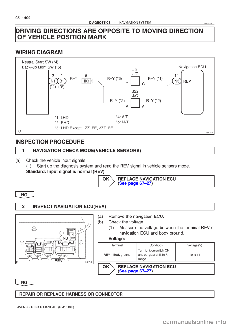
I34724
Neutral Start SW (*4)
Back±up Light SW (*5)21
N1B1
(*4)(*5) 5
IK1
R±YR±Y (*3)R±Y (*1)
R±Y (*2)R±Y (*2)AA
CC
J5
J/C
J22
J/C 14
N3
Navigation ECU
REV
*1: LHD
*2: RHD
*3: LHD Except 1ZZ±FE, 3ZZ±FE *4: A/T
*5: M/T
I32703REV
N3
05±1490
±
DIAGNOSTICS NAVIGATION SYSTEM
AVENSIS REPAIR MANUAL (RM1018E)
DRIVING DIRECTIONS ARE OPPOSITE TO MOVING DIRECTION OF VEHICLE POSITION MARK
WIRING DIAGRAM
INSPECTION PROCEDURE
1NAVIGATION CHECK MODE(VEHICLE SENSORS)
(a)Check the vehicle input signals.
(1)Start up the diagnosis system and read the REV signal in vehicle sensors\
mode.
Standard: Input signal is normal (REV)
OKREPLACE NAVIGATION ECU (See page 67±27)
NG
2INSPECT NAVIGATION ECU(REV)
(a)Remove the navigation ECU.
(b)Check the voltage. (1)Measure the voltage between the terminal REV ofnavigation ECU and body ground.
Voltage:
TerminalConditionVoltage (V)
REV ±Body ground
Turn ignition switch ON
and put gear shift in R
range
10 to 14
OKREPLACE NAVIGATION ECU (See page 67±27)
NG
REPAIR OR REPLACE HARNESS OR CONNECTOR
05C3U±01
Page 1546 of 5135
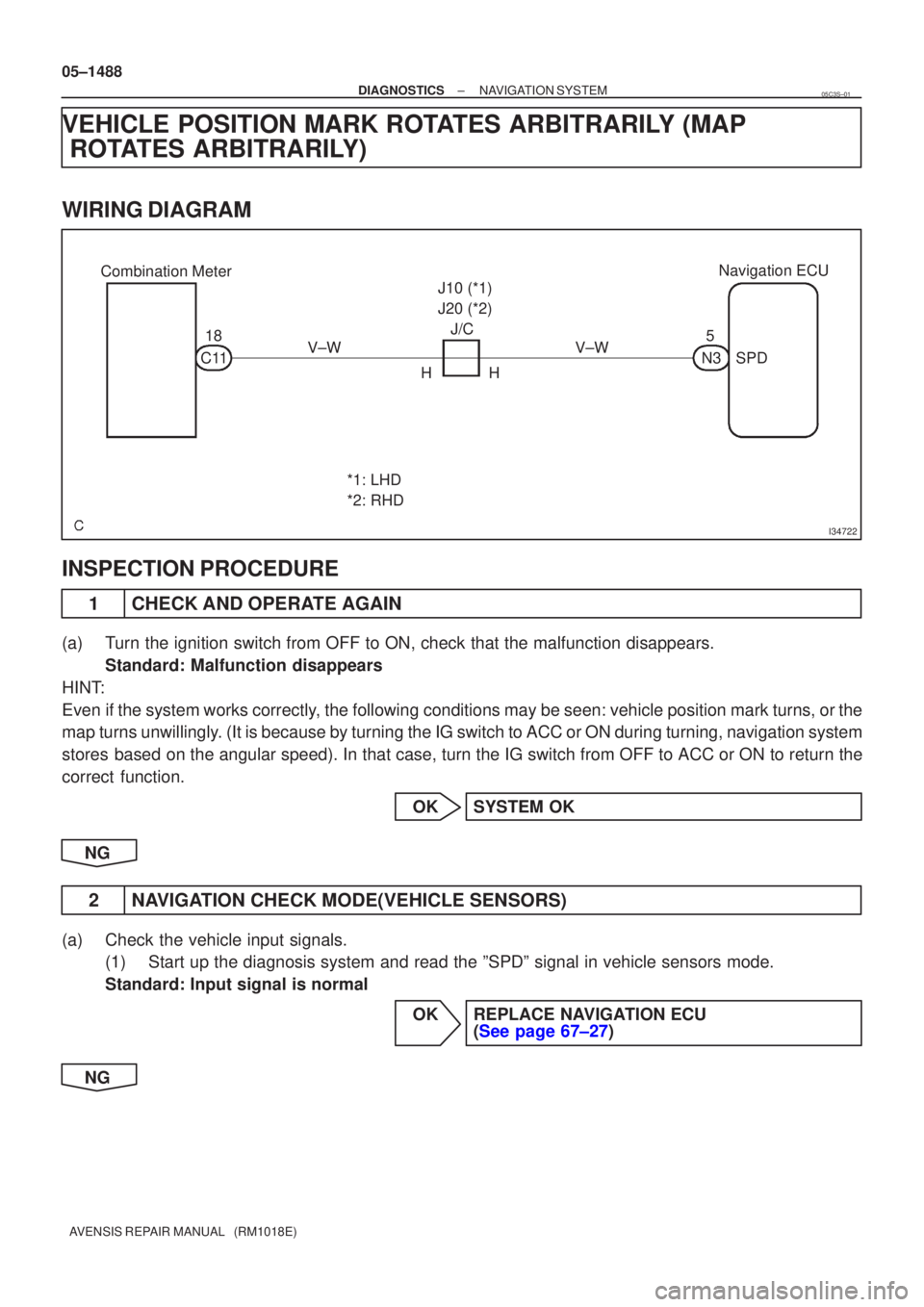
I34722
Combination MeterNavigation ECU
18
C11 V±W J/C
HH J10 (*1)
J20 (*2)
V±W
*1: LHD
*2: RHD 5
N3SPD
05±1488
±
DIAGNOSTICS NAVIGATION SYSTEM
AVENSIS REPAIR MANUAL (RM1018E)
VEHICLE POSITION MARK ROTATES ARBITRARILY (MAP ROTATES ARBITRARILY)
WIRING DIAGRAM
INSPECTION PROCEDURE
1CHECK AND OPERATE AGAIN
(a)Turn the ignition switch from OFF to ON, check that the malfunction disappea\
rs.
Standard: Malfunction disappears
HINT:
Even if the system works correctly, the following conditions may be seen: vehicle position mark turns, or the
map turns unwillingly. (It is because by turning the IG switch to ACC or ON during turning, \
navigation system
stores based on the angular speed). In that case, turn the IG switch from OFF to ACC\
or ON to return the
correct function.
OKSYSTEM OK
NG
2NAVIGATION CHECK MODE(VEHICLE SENSORS)
(a)Check the vehicle input signals. (1)Start up the diagnosis system and read the ºSPDº signal in vehicle\
sensors mode.
Standard: Input signal is normal
OKREPLACE NAVIGATION ECU (See page 67±27)
NG
05C3S±01
Page 1547 of 5135
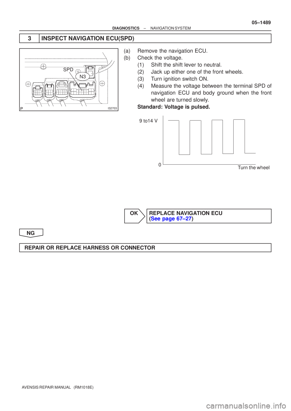
I32703
SPD
N3
9 to14 V0 Turn the wheel
±
DIAGNOSTICS NAVIGATION SYSTEM
05±1489
AVENSIS REPAIR MANUAL (RM1018E)
3INSPECT NAVIGATION ECU(SPD)
(a)Remove the navigation ECU.
(b)Check the voltage.
(1)Shift the shift lever to neutral.
(2)Jack up either one of the front wheels.
(3)Turn ignition switch ON.
(4)Measure the voltage between the terminal SPD ofnavigation ECU and body ground when the front
wheel are turned slowly.
Standard: Voltage is pulsed.
OKREPLACE NAVIGATION ECU (See page 67±27)
NG
REPAIR OR REPLACE HARNESS OR CONNECTOR
Page 1548 of 5135
±
DIAGNOSTICS NAVIGATION SYSTEM
05±1487
AVENSIS REPAIR MANUAL (RM1018E)
GPS MARK DOES NOT APPEAR
INSPECTION PROCEDURE
1CHECK MARK DISPLAY
(a)Check that the malfunction disappears when placing the vehicle outdoors with \
a good view.
Standard: GPS mark is displayed.
HINT:
At the place surrounded by the architecture, the vehicle cannot receive \
the GPS radio wave.
OKSYSTEM OK
NG
2CHECK OPTIONAL COMPONENT
(a)Check for optional component. (1)Check if there are any optional components on the vehicle.
Standard: There are no optional components on the vehicle.
(2)Check if there is anything such as film stuck to the window or any metal obje\
cts on the instrument
panel.
Standard: There is nothing such as film stuck to the window or any metal objects on the instru-
ment panel.
NGEFFECT FROM OPTIONAL COMPONENT
OK
3REPLACE NAVIGATION ANTENNA ASSY (See page 67±28)
Standard: Normally returns. NG REPLACE NAVIGATION ECU (See page 67±27)
OK
SYSTEM OK
05C3R±01
Page 1549 of 5135
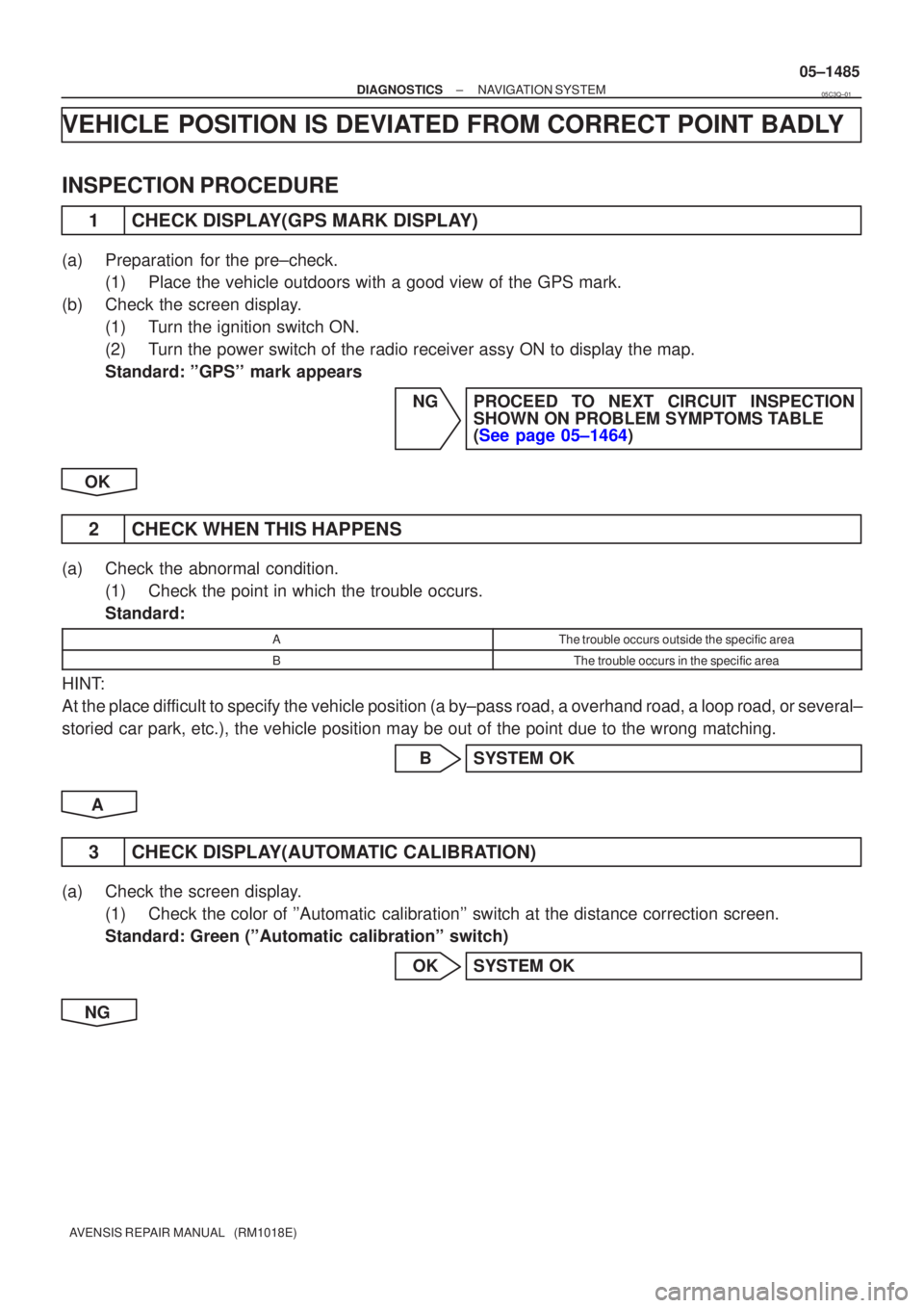
±
DIAGNOSTICS NAVIGATION SYSTEM
05±1485
AVENSIS REPAIR MANUAL (RM1018E)
VEHICLE POSITION IS DEVIATED FROM CORRECT POINT BADLY
INSPECTION PROCEDURE
1CHECK DISPLAY(GPS MARK DISPLAY)
(a)Preparation for the pre±check.
(1)Place the vehicle outdoors with a good view of the GPS mark.
(b)Check the screen display. (1)Turn the ignition switch ON.
(2)Turn the power switch of the radio receiver assy ON to display the map.
Standard: ''GPS'' mark appears
NGPROCEED TO NEXT CIRCUIT INSPECTIONSHOWN ON PROBLEM SYMPTOMS TABLE
(See page 05±1464)
OK
2 CHECK WHEN THIS HAPPENS
(a) Check the abnormal condition. (1) Check the point in which the trouble occurs.
Standard:
AThe trouble occurs outside the specific area
BThe trouble occurs in the specific area
HINT:
At the place difficult to specify the vehicle position (a by±pass road, a overhand r\
oad, a loop road, or several±
storied car park, etc.), the vehicle position may be out of the point due to t\
he wrong matching.
B SYSTEM OK
A
3 CHECK DISPLAY(AUTOMATIC CALIBRATION)
(a) Check the screen display. (1) Check the color of ''Automatic calibration'' switch at the distance correction screen.
Standard: Green (''Automatic calibration'' switch)
OK SYSTEM OK
NG
05C3Q±01
Page 1550 of 5135
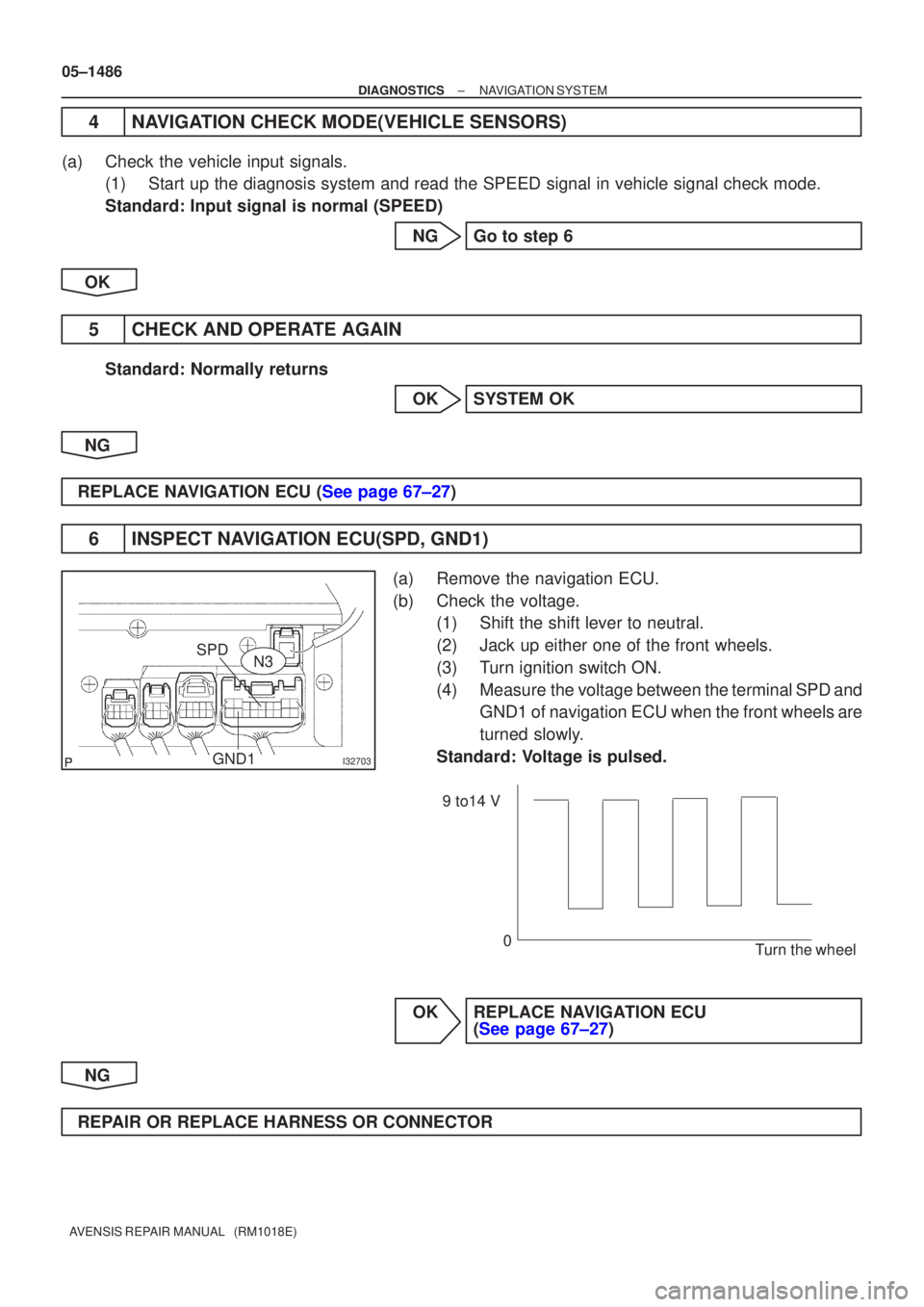
I32703
SPDGND1N3
9 to14 V
0 Turn the wheel
05±1486
±
DIAGNOSTICS NAVIGATION SYSTEM
AVENSIS REPAIR MANUAL (RM1018E)
4NAVIGATION CHECK MODE(VEHICLE SENSORS)
(a)Check the vehicle input signals. (1)Start up the diagnosis system and read the SPEED signal in vehicle signa\
l check mode.
Standard: Input signal is normal (SPEED)
NGGo to step 6
OK
5CHECK AND OPERATE AGAIN
Standard: Normally returns OKSYSTEM OK
NG
REPLACE NAVIGATION ECU (See page 67±27)
6INSPECT NAVIGATION ECU(SPD, GND1)
(a)Remove the navigation ECU.
(b)Check the voltage. (1)Shift the shift lever to neutral.
(2)Jack up either one of the front wheels.
(3)Turn ignition switch ON.
(4)Measure the voltage between the terminal SPD andGND1 of navigation ECU when the front wheels are
turned slowly.
Standard: Voltage is pulsed.
OKREPLACE NAVIGATION ECU (See page 67±27)
NG
REPAIR OR REPLACE HARNESS OR CONNECTOR