ECO TOYOTA AYGO X 2022 (in English) User Guide
[x] Cancel search | Manufacturer: TOYOTA, Model Year: 2022, Model line: AYGO X, Model: TOYOTA AYGO X 2022Pages: 494, PDF Size: 92.53 MB
Page 54 of 494
52
Owner's Manual_Europe_M99V08_en
1-2. Child safety
■Child restraint system compat-
ibility for each seating posi-
tion
Compatibility of each seating posi-
tion with child restraint systems
( P.53) displays the type of child
restraint systems that can be used
and possible seating positions for
installation using symbols.
Also, the recommended child
restraint system that is suitable for
your child can be selected.
Otherwise, check [Recommended
child restraint systems information]
for recommended child restraint
systems. ( P. 5 7 )
Check the selected child restraint
system together with the following
[Before confirming the compatibility
of each seating position with child
restraint systems].
■Before confirming the compat-
ibility of each seating position
with child restraint systems
1 Checking the child restraint sys-
tem standards.
Use a child restraint system that
conforms to UN (ECE) R44*1 or
UN (ECE) R129*1, 2.
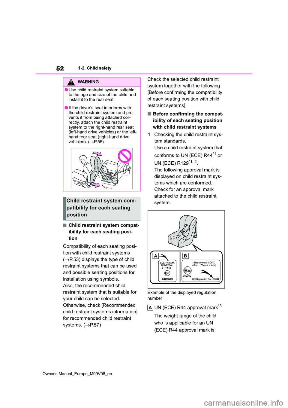
The following approval mark is
displayed on child restraint sys-
tems which are conformed.
Check for an approval mark
attached to the child restraint
system.
Example of the displayed regulation
number
UN (ECE) R44 approval mark*3
The weight range of the child
who is applicable for an UN
(ECE) R44 approval mark is
WARNING
●Use child restraint system suitable to the age and size of the child and
install it to the rear seat.
●If the driver’s seat interferes with
the child restraint system and pre- vents it from being attached cor-rectly, attach the child restraint
system to the right-hand rear seat (left-hand drive vehicles) or the left-hand rear seat (right-hand drive
vehicles). ( P. 5 5 )
Child restraint system com-
patibility for each seating
position
Page 56 of 494
54
Owner's Manual_Europe_M99V08_en
1-2. Child safety
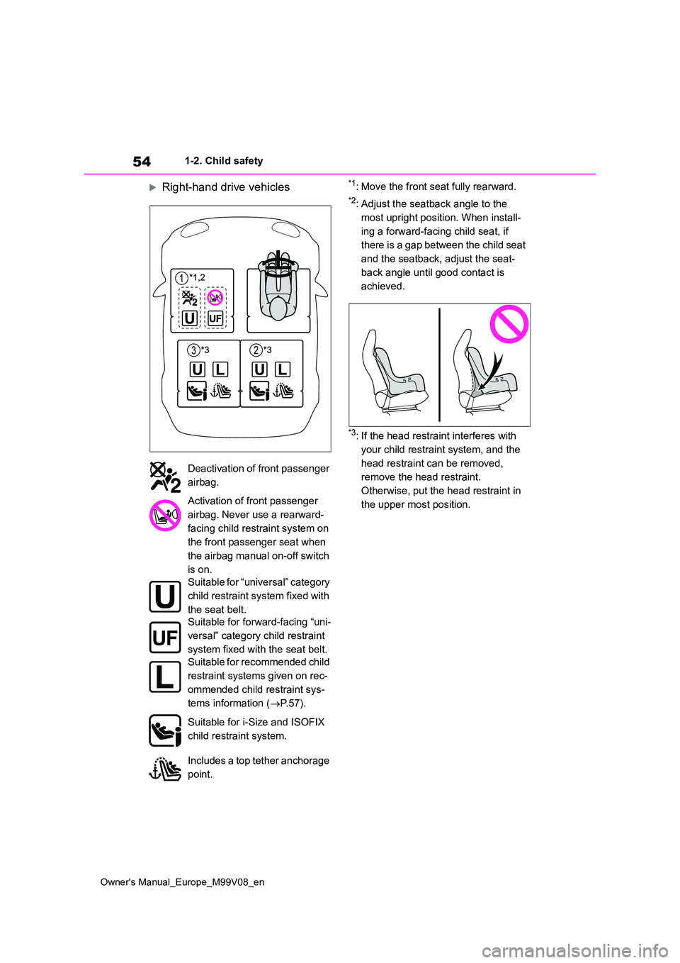
Right-hand drive vehicles*1: Move the front seat fully rearward.
*2: Adjust the seatback angle to the
most upright position. When install-
ing a forward-facing child seat, if
there is a gap between the child seat
and the seatback, adjust the seat-
back angle until good contact is
achieved.
*3: If the head restraint interferes with
your child restraint system, and the
head restraint can be removed,
remove the head restraint.
Otherwise, put the head restraint in
the upper most position.
Deactivation of front passenger
airbag.
Activation of front passenger
airbag. Never use a rearward-
facing child restraint system on
the front passenger seat when
the airbag manual on-off switch
is on.
Suitable for “universal” category
child restraint system fixed with
the seat belt.
Suitable for forward-facing “uni-
versal” category child restraint
system fixed with the seat belt.
Suitable for recommended child
restraint systems given on rec-
ommended child restraint sys-
tems information ( P. 5 7 ) .
Suitable for i-Size and ISOFIX
child restraint system.
Includes a top tether anchorage
point.
Page 59 of 494
57
1
Owner's Manual_Europe_M99V08_en
1-2. Child safety
For safety and security
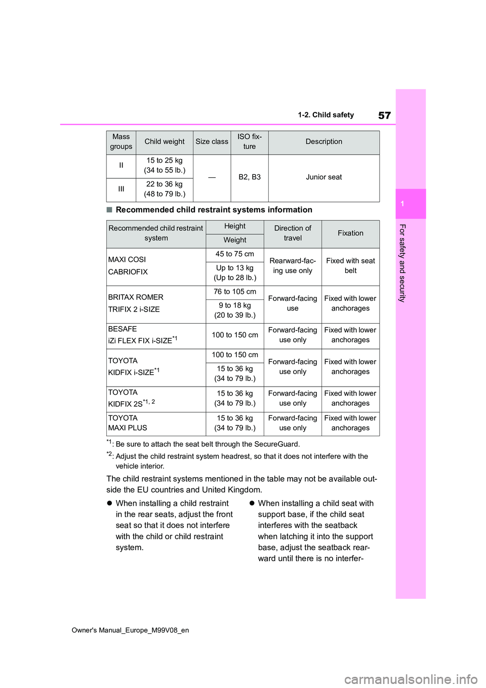
■Recommended child restraint systems information
*1: Be sure to attach the seat belt through the SecureGuard.
*2: Adjust the child restraint system headrest, so that it does not interfere with the
vehicle interior.
The child restraint systems mentioned in the table may not be a vailable out-
side the EU countries and United Kingdom.
When installing a child restraint
in the rear seats, adjust the front
seat so that it does not interfere
with the child or child restraint
system.
When installing a child seat with
support base, if the child seat
interferes with the seatback
when latching it into the support
base, adjust the seatback rear-
ward until there is no interfer-
II15 to 25 kg
(34 to 55 lb.)—B2, B3Junior seat
III22 to 36 kg
(48 to 79 lb.)
Recommended child restraint
system
HeightDirection of
travelFixationWeight
MAXI COSI
CABRIOFIX
45 to 75 cmRearward-fac-
ing use only
Fixed with seat
beltUp to 13 kg
(Up to 28 lb.)
BRITAX ROMER
TRIFIX 2 i-SIZE
76 to 105 cmForward-facing
use
Fixed with lower
anchorages9 to 18 kg
(20 to 39 lb.)
BESAFE
iZi FLEX FIX i-SIZE*1100 to 150 cmForward-facing
use only
Fixed with lower
anchorages
TOYOTA
KIDFIX i-SIZE*1
100 to 150 cmForward-facing
use only
Fixed with lower
anchorages15 to 36 kg
(34 to 79 lb.)
TOYOTA
KIDFIX 2S*1, 215 to 36 kg
(34 to 79 lb.)
Forward-facing
use only
Fixed with lower
anchorages
TOYOTA
MAXI PLUS
15 to 36 kg
(34 to 79 lb.)
Forward-facing
use only
Fixed with lower
anchorages
Mass
groupsChild weightSize classISO fix-
tureDescription
Page 63 of 494
61
1
Owner's Manual_Europe_M99V08_en
1-2. Child safety
For safety and security
Since the seat belt automatically reels
itself, slowly return it to the stowing
position.
■When installing a child restraint system
You may need a locking clip to install the
child restraint system. Follow the instructions provided by the manufac-turer of the system. If your child restraint
system does not provide a locking clip, you can purchase the following item from any authorized Toyota retailer or
Toyota authorized repairer, or any reli- able repairer: Locking clip for child restraint system
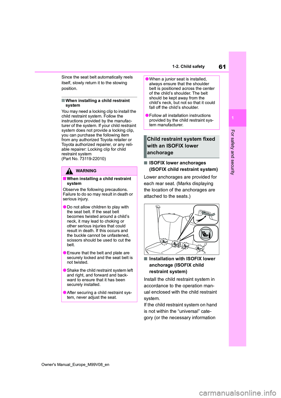
(Part No. 73119-22010)■ISOFIX lower anchorages
(ISOFIX child restraint system)
Lower anchorages are provided for
each rear seat. (Marks displaying
the location of the anchorages are
attached to the seats.)
■Installation with ISOFIX lower
anchorage (ISOFIX child
restraint system)
Install the child restraint system in
accordance to the operation man-
ual enclosed with the child restraint
system.
If the child restraint system on hand
is not within the “universal” cate-
gory (or the necessary information
WARNING
■When installing a child restraint
system
Observe the following precautions. Failure to do so may result in death or
serious injury.
●Do not allow children to play with
the seat belt. If the seat belt becomes twisted around a child’s neck, it may lead to choking or
other serious injuries that could result in death. If this occurs and the buckle cannot be unfastened,
scissors should be used to cut the belt.
●Ensure that the belt and plate are securely locked and the seat belt is not twisted.
●Shake the child restraint system left and right, and forward and back-
ward to ensure that it has been securely installed.
●After securing a child restraint sys-tem, never adjust the seat.
●When a junior seat is installed, always ensure that the shoulder belt is positioned across the center
of the child’s shoulder. The belt should be kept away from the child’s neck, but not so that it could
fall off the child’s shoulder.
●Follow all installation instructions
provided by the child restraint sys- tem manufacturer.
Child restraint system fixed
with an ISOFIX lower
anchorage
Page 67 of 494
65
1
Owner's Manual_Europe_M99V08_en
1-3. Emergency assistance
For safety and security
tance required.
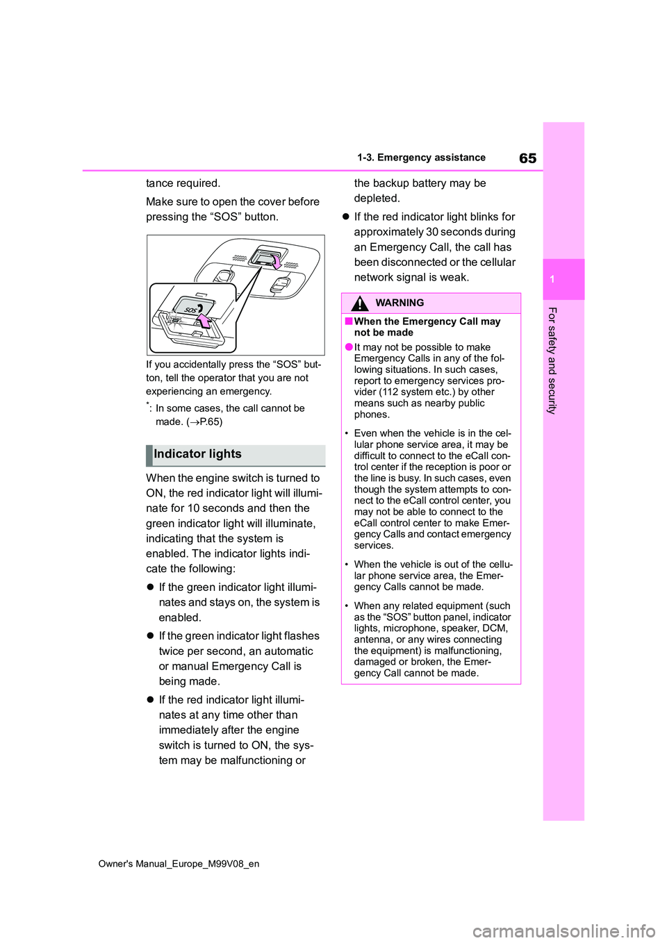
Make sure to open the cover before
pressing the “SOS” button.
If you accidentally press the “SOS” but-
ton, tell the operator that you are not
experiencing an emergency.
*: In some cases, the call cannot be
made. ( P. 6 5 )
When the engine switch is turned to
ON, the red indicator light will illumi-
nate for 10 seconds and then the
green indicator light will illuminate,
indicating that the system is
enabled. The indicator lights indi-
cate the following:
If the green indicator light illumi-
nates and stays on, the system is
enabled.
If the green indicator light flashes
twice per second, an automatic
or manual Emergency Call is
being made.
If the red indicator light illumi-
nates at any time other than
immediately after the engine
switch is turned to ON, the sys-
tem may be malfunctioning or
the backup battery may be
depleted.
If the red indicator light blinks for
approximately 30 seconds during
an Emergency Call, the call has
been disconnected or the cellular
network signal is weak.
Indicator lights
WARNING
■When the Emergency Call may not be made
●It may not be possible to make Emergency Calls in any of the fol-lowing situations. In such cases,
report to emergency services pro- vider (112 system etc.) by other means such as nearby public
phones.
• Even when the vehicle is in the cel-
lular phone service area, it may be difficult to connect to the eCall con-trol center if the reception is poor or
the line is busy. In such cases, even though the system attempts to con-nect to the eCall control center, you
may not be able to connect to the eCall control center to make Emer-gency Calls and contact emergency
services.
• When the vehicle is out of the cellu-
lar phone service area, the Emer- gency Calls cannot be made.
• When any related equipment (such as the “SOS” button panel, indicator lights, microphone, speaker, DCM,
antenna, or any wires connecting the equipment) is malfunctioning, damaged or broken, the Emer-
gency Call cannot be made.
Page 68 of 494
66
Owner's Manual_Europe_M99V08_en
1-3. Emergency assistance
WARNING
• During an Emergency Call, the sys- tem makes repeated attempts to
connect to the eCall control center. However, if it cannot connect to the eCall control center due to poor
radio wave reception, the system may not be able to connect to the cellular network and the call may
finish without connecting. The red indicator light will blink for approxi-mately 30 seconds to indicate this
disconnection.
●If t he b at t er y ’s vo lt a g e d ec r ea se s o r
there is a disconnection, the system may not be able to connect to the eCall control center.
●The Emergency Call system might not work outside of EU area,
depending on the available infra- structure in the country.
■When the Emergency Call sys-tem is replaced with a new one
The Emergency Call system should
be registered. Contact any authorized Toyota retailer or Toyota authorized repairer, or any reliable repairer.
■For your safety
●Please drive safely.
The function of this system is to assist you in making the Emer-gency Call in case of accidents
such as traffic accidents or sudden medical emergencies, and it does not protect the driver or passengers
in any way. Please drive safely and fasten your seatbelts at all times for your safety.
●In case of an emergency, make lives the top priority.
●If you smell anything burning or other unusual smells, leave the
vehicle and evacuate to a safe area immediately.
●If the airbags deploy when the sys-tem is operating normally, the sys-tem makes emergency call. The
system also makes emergency call when the vehicle is struck from the r e a r o r r ol l s ov er, ev e n i f t h e a ir b a gs
do not deploy.
●For safety, do not make the Emer-
gency Call while driving. Making calls during driving may cause mishandling of the steering
wheel, which may lead to unex- pected accidents.Stop the vehicle and confirm the
safety of your surroundings before making the Emergency Call.
●When changing fuses, please use the specified fuses. Using other fuses may cause ignition or smoke
in the circuit and lead to a fire.
●Using the system while there is
smoke or an unusual smell may cause a fire. Stop using the system immediately and consult any autho-
rized Toyota retailer or Toyota authorized repairer, or any reliable repairer.
NOTICE
■To prevent damage
Do not pour any liquids onto the “SOS” button panel, etc. and do not
impact it.
■If the “SOS” button panel,
speaker or microphone malfunc- tions during an Emergency Call or manual maintenance check
It may not be possible to make Emer- gency Calls, confirm the system sta-tus, or communicate with the eCall
control center operator. If any of the above equipment is damaged, please consult any authorized Toyota retailer
or Toyota authorized repairer, or any reliable repairer.
Page 80 of 494
78
Owner's Manual_Europe_M99V08_en
2-1. Instrument cluster
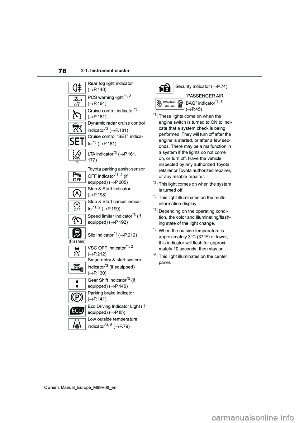
*1: These lights come on when the
engine switch is turned to ON to indi-
cate that a system check is being
performed. They will turn off after the
engine is started, or after a few sec-
onds. There may be a malfunction in
a system if the lights do not come
on, or turn off. Have the vehicle
inspected by any authorized Toyota
retailer or Toyota authorized repairer,
or any reliable repairer.
*2: This light comes on when the system
is turned off.
*3: This light illuminates on the multi-
information display.
*4: Depending on the operating condi-
tion, the color and illuminating/flash-
ing state of the light change.
*5: When the outside temperature is
approximately 3°C (37°F) or lower,
this indicator will flash for approxi-
mately 10 seconds, then stay on.
*6: This light illuminates on the center
panel.
Rear fog light indicator
( P.148)
PCS warning light*1, 2
( P.164)
Cruise control indicator*3
( P.181)
Dynamic radar cruise control
indicator*3 ( P.181)
Cruise control “SET” indica-
tor*3 ( P.181)
*4
LTA indicator*3 (P.161,
177)
Toyota parking assist-sensor
OFF indicator*1, 2 (if
equipped) ( P.205)
Stop & Start indicator
( P.198)
Stop & Start cancel indica-
tor*1, 2 ( P.199)
Speed limiter indicator*3 (if
equipped) ( P.192)
(Flashes)
Slip indicator*1 (P.212)
VSC OFF indicator*1, 2
( P.212)
Smart entry & start system
indicator*3 (if equipped)
( P.130)
Gear Shift Indicator*3 (if
equipped) ( P.140)
Parking brake indicator
( P.141)
Eco Driving Indicator Light (if
equipped) ( P. 8 5 )
Low outside temperature
indicator*3, 5 ( P. 7 9 )
Security indicator (P. 7 4 )
“PASSENGER AIR
BAG” indicator*1, 6
( P.45)
Page 82 of 494
80
Owner's Manual_Europe_M99V08_en
2-1. Instrument cluster
Outside temperature
Displays the outside temperature within the range of -40°C (-40°F) to 60°C (140°F)
■Outside temperature display
●In the following situations, the correct outside temperature may not be dis-
played, or the display may take longer than normal to change:• When stopped, or driving at low
speeds (less than 25 km/h [16 mph]) • When the outside temperature has changed suddenly (at the
entrance/exit of a garage, tunnel, etc.)
●When “--” is displayed, the system
may be malfunctioning. Take your vehicle to any authorized Toyota retailer or Toyota authorized repairer,
or any reliable repairer.
■Fuel gauge and driving range dis- play
The fuel gauge and driving range dis-
play are linked. If the fuel gauge and driving range display do not update after refueling a small amount, they can be
updated by performing the following pro- cedure:
1 Stop the vehicle on a level surface.
Wait until the fuel in the fuel tank stabi- lizes.
2 Press or to select of the
multi-information display.
3 Press or to select .
4 Press to change the odometer
and trip meter display to the odome-
ter.
5 Turn the engine switch off.
6 While pressing and holding the
meter control switch, turn the engine
switch to ON.
7 Continue holding the meter
control switch for approximately 5
seconds.
Release the button when the odometer begins blinking.
Updating will be complete when the odometer blinks for approximately 5 seconds and then returns to the normal
display.
■Liquid crystal display
P. 8 3
■Customization
The gauges and meters can be custom-
ized in of the multi-information dis-
play. ( P.355)
WARNING
■The information display at low temperatures
Allow the interior of the vehicle to warm up before using the liquid crys-tal information display. At extremely
low temperatures, the information dis- play monitor may respond slowly, and display changes may be delayed.
For example, there is a lag between the driver’s shifting and the new gear
number appearing on the display. This lag could cause the driver to downshift again, causing rapid and
excessive engine braking and possi- bly an accident resulting in death or injury.
NOTICE
■To prevent damage to the engine
and its components
Do not let the indicator of the tachom- eter enter the red zone, which indi-
cates the maximum engine speed.
Page 83 of 494
81
2
Owner's Manual_Europe_M99V08_en
2-1. Instrument cluster
Vehicle status information and indicators
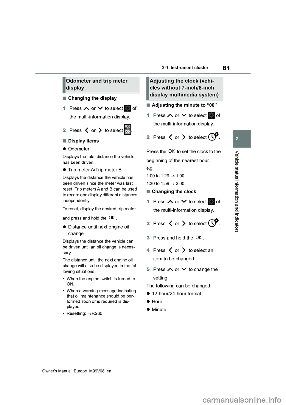
■Changing the display
1 Press or to select of
the multi-information display.
2 Press or to select .
■Display items
Odometer
Displays the total distance the vehicle
has been driven.
Trip meter A/Trip meter B
Displays the distance the vehicle has
been driven since the meter was last
reset. Trip meters A and B can be used
to record and display different distances
independently.
To reset, display the desired trip meter
and press and hold the .
Distance until next engine oil
change
Displays the distance the vehicle can
be driven until an oil change is neces-
sary.
The distance until the next engine oil
change will also be displayed in the fol-
lowing situations:
• When the engine switch is turned to
ON.
• When a warning message indicating
that oil maintenance should be per-
formed soon or is required is dis-
played.
• Resetting: P. 2 6 0
■Adjusting the minute to “00”
1 Press or to select of
the multi-information display.
2 Press or to select .
Press the to set the clock to the
beginning of the nearest hour.
e.g.
1:00 to 1:29 1:00
1:30 to 1:59 2:00
■Changing the clock
1 Press or to select of
the multi-information display.
2 Press or to select .
3 Press and hold the .
4 Press or to select an
item to be changed.
5 Press or to change the
setting.
The following can be changed:
12-hour/24-hour format
Hour
Minute
Odometer and trip meter
display
Adjusting the clock (vehi-
cles without 7-inch/8-inch
display multimedia system)
Page 86 of 494
84
Owner's Manual_Europe_M99V08_en
2-1. Instrument cluster
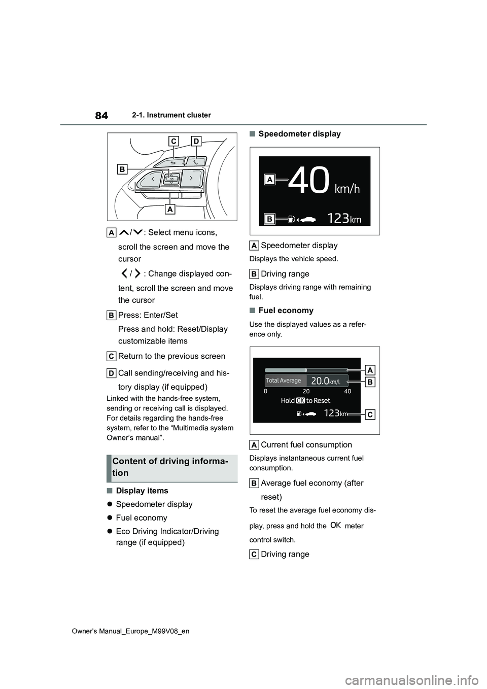
/ : Select menu icons,
scroll the screen and move the
cursor
/ : Change displayed con-
tent, scroll the screen and move
the cursor
Press: Enter/Set
Press and hold: Reset/Display
customizable items
Return to the previous screen
Call sending/receiving and his-
tory display (if equipped)
Linked with the hands-free system,
sending or receiving call is displayed.
For details regarding the hands-free
system, refer to the “Multimedia system
Owner’s manual”.
■Display items
Speedometer display
Fuel economy
Eco Driving Indicator/Driving
range (if equipped)
■Speedometer display
Speedometer display
Displays the vehicle speed.
Driving range
Displays driving range with remaining
fuel.
■Fuel economy
Use the displayed values as a refer-
ence only.
Current fuel consumption
Displays instantaneous current fuel
consumption.
Average fuel economy (after
reset)
To reset the average fuel economy dis-
play, press and hold the meter
control switch.
Driving range
Content of driving informa-
tion