TOYOTA CAMRY V20 1986 Service Information
Manufacturer: TOYOTA, Model Year: 1986, Model line: CAMRY V20, Model: TOYOTA CAMRY V20 1986Pages: 2389, PDF Size: 84.44 MB
Page 1171 of 2389
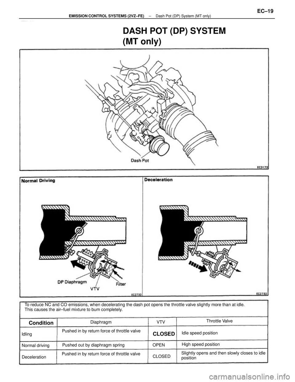
To reduce NC and CO emissions, when decelerating the dash pot opens the throttle valve slightly more than at idle.
This causes the air±fuel mixture to bum completely.
DASH POT (DP) SYSTEM
(MT only)
Slightly opens and then slowly closes to idle
position Pushed in by return force of throttle valve
Pushed in by return force of throttle valvePushed out by diaphragm springHigh speed position Idle speed positionThrottle Valve
Normal driving
DecelerationDiaphragm
Condition
CLOSED
CLOSED Idling
OPENVTV
± EMISSION CONTROL SYSTEMS (2VZ±FE)Dash Pot (DP) System (MT only)EC±19
Page 1172 of 2389
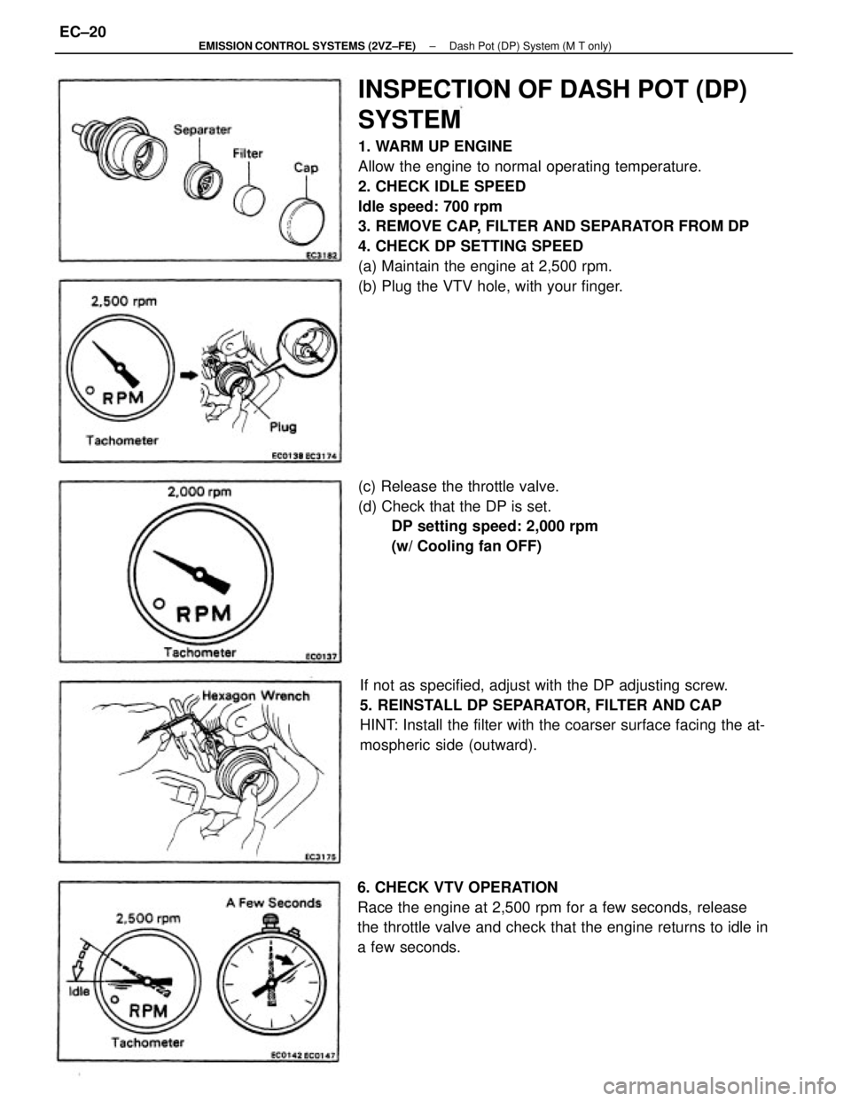
INSPECTION OF DASH POT (DP)
SYSTEM
1. WARM UP ENGINE
Allow the engine to normal operating temperature.
2. CHECK IDLE SPEED
Idle speed: 700 rpm
3. REMOVE CAP, FILTER AND SEPARATOR FROM DP
4. CHECK DP SETTING SPEED
(a) Maintain the engine at 2,500 rpm.
(b) Plug the VTV hole, with your finger.
If not as specified, adjust with the DP adjusting screw.
5. REINSTALL DP SEPARATOR, FILTER AND CAP
HINT: Install the filter with the coarser surface facing the at-
mospheric side (outward).
6. CHECK VTV OPERATION
Race the engine at 2,500 rpm for a few seconds, release
the throttle valve and check that the engine returns to idle in
a few seconds.(c) Release the throttle valve.
(d) Check that the DP is set.
DP setting speed: 2,000 rpm
(w/ Cooling fan OFF)
± EMISSION CONTROL SYSTEMS (2VZ±FE)Dash Pot (DP) System (M T only)EC±20
Page 1173 of 2389
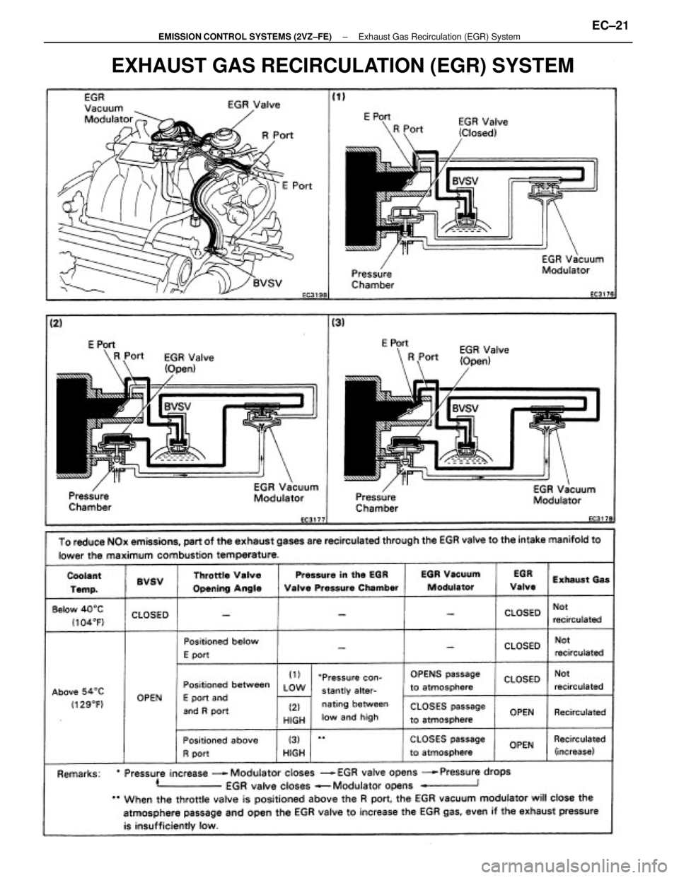
EXHAUST GAS RECIRCULATION (EGR) SYSTEM
± EMISSION CONTROL SYSTEMS (2VZ±FE)Exhaust Gas Recirculation (EGR) SystemEC±21
Page 1174 of 2389
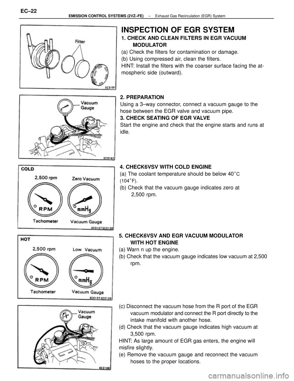
(c) Disconnect the vacuum hose from the R port of the EGR
vacuum modulator and connect the R port directly to the
intake manifold with another hose.
(d) Check that the vacuum gauge indicates high vacuum at
3,500 rpm.
HINT: As large amount of EGR gas enters, the engine will
misfire slightly.
(e) Remove the vacuum gauge and reconnect the vacuum
hoses to the proper locations.
INSPECTION OF EGR SYSTEM
1. CHECK AND CLEAN FILTERS IN EGR VACUUM
MODULATOR
(a) Check the filters for contamination or damage.
(b) Using compressed air, clean the filters.
HINT: Install the filters with the coarser surface facing the at-
mospheric side (outward).
2. PREPARATION
Using a 3±way connector, connect a vacuum gauge to the
hose between the EGR valve and vacuum pipe.
3. CHECK SEATING OF EGR VALVE
Start the engine and check that the engine starts and runs at
idle.
4. CHECK6VSV WITH COLD ENGINE
(a) The coolant temperature should be below 40
°C
(104°F).
(b) Check that the vacuum gauge indicates zero at
2,500 rpm.
5. CHECK6VSV AND EGR VACUUM MODULATOR
WITH HOT ENGINE
(a) Warn n up the engine.
(b) Check that the vacuum gauge indicates low vacuum at 2,500
rpm.
± EMISSION CONTROL SYSTEMS (2VZ±FE)Exhaust Gas Recirculation (EGR) SystemEC±22
Page 1175 of 2389
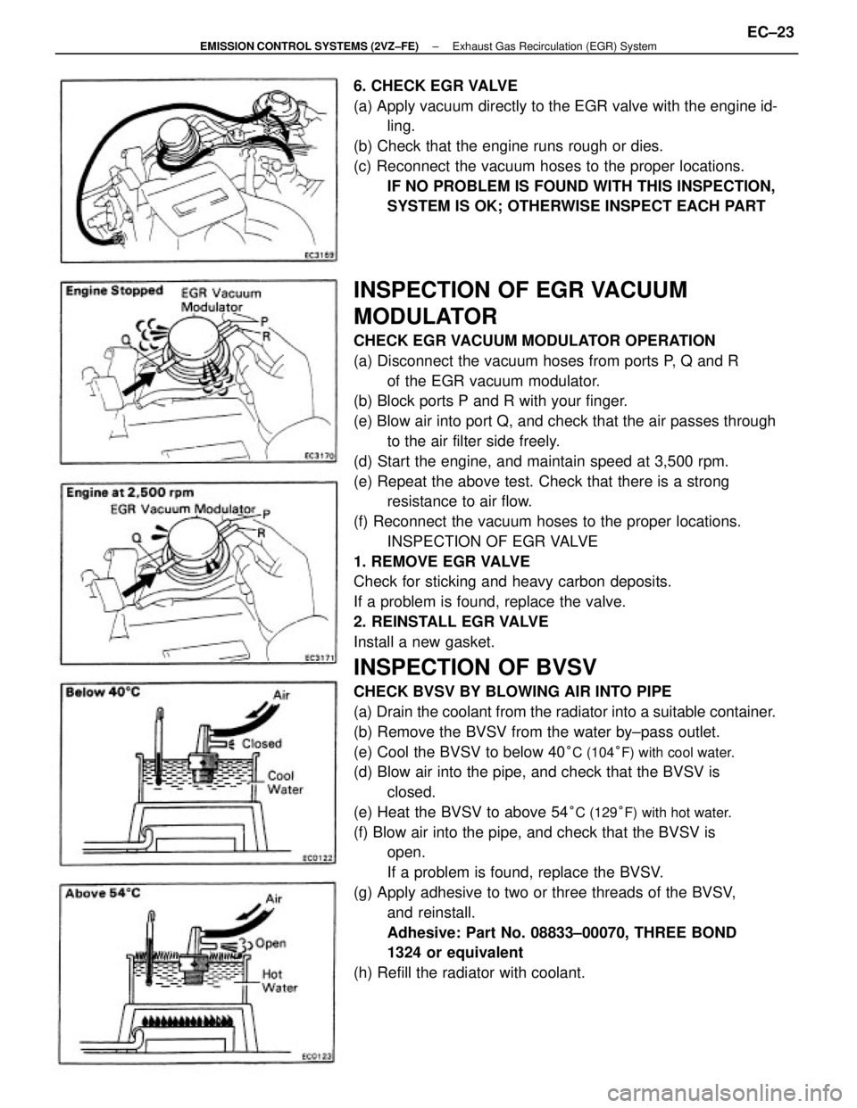
INSPECTION OF EGR VACUUM
MODULATOR
CHECK EGR VACUUM MODULATOR OPERATION
(a) Disconnect the vacuum hoses from ports P, Q and R
of the EGR vacuum modulator.
(b) Block ports P and R with your finger.
(e) Blow air into port Q, and check that the air passes through
to the air filter side freely.
(d) Start the engine, and maintain speed at 3,500 rpm.
(e) Repeat the above test. Check that there is a strong
resistance to air flow.
(f) Reconnect the vacuum hoses to the proper locations.
INSPECTION OF EGR VALVE
1. REMOVE EGR VALVE
Check for sticking and heavy carbon deposits.
If a problem is found, replace the valve.
2. REINSTALL EGR VALVE
Install a new gasket.
INSPECTION OF BVSV
CHECK BVSV BY BLOWING AIR INTO PIPE
(a) Drain the coolant from the radiator into a suitable container.
(b) Remove the BVSV from the water by±pass outlet.
(e) Cool the BVSV to below 40
°C (104°F) with cool water.
(d) Blow air into the pipe, and check that the BVSV is
closed.
(e) Heat the BVSV to above 54
°C (129°F) with hot water.
(f) Blow air into the pipe, and check that the BVSV is
open.
If a problem is found, replace the BVSV.
(g) Apply adhesive to two or three threads of the BVSV,
and reinstall.
Adhesive: Part No. 08833±00070, THREE BOND
1324 or equivalent
(h) Refill the radiator with coolant. 6. CHECK EGR VALVE
(a) Apply vacuum directly to the EGR valve with the engine id-
ling.
(b) Check that the engine runs rough or dies.
(c) Reconnect the vacuum hoses to the proper locations.
IF NO PROBLEM IS FOUND WITH THIS INSPECTION,
SYSTEM IS OK; OTHERWISE INSPECT EACH PART
± EMISSION CONTROL SYSTEMS (2VZ±FE)Exhaust Gas Recirculation (EGR) SystemEC±23
Page 1176 of 2389
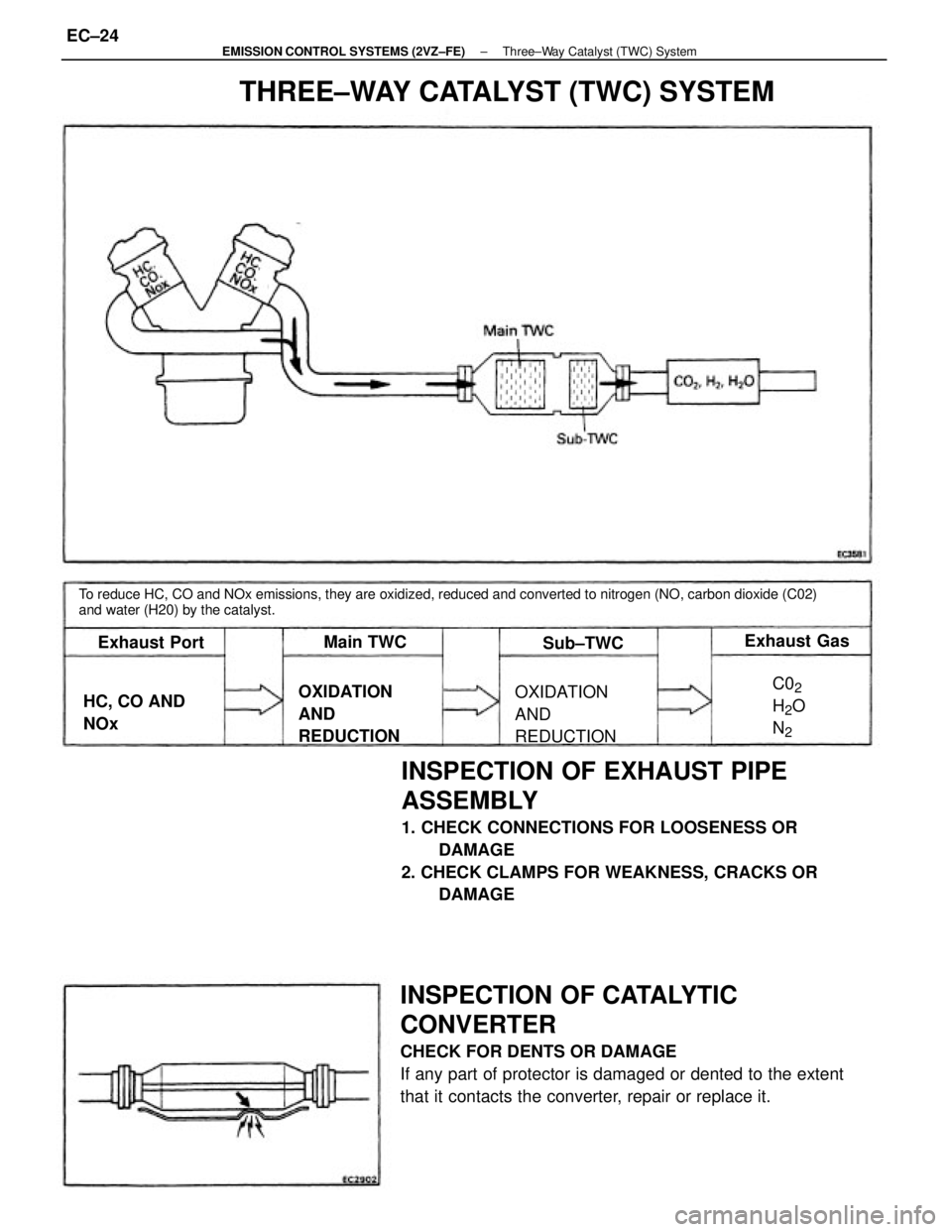
INSPECTION OF EXHAUST PIPE
ASSEMBLY
1. CHECK CONNECTIONS FOR LOOSENESS OR
DAMAGE
2. CHECK CLAMPS FOR WEAKNESS, CRACKS OR
DAMAGE
INSPECTION OF CATALYTIC
CONVERTER
CHECK FOR DENTS OR DAMAGE
If any part of protector is damaged or dented to the extent
that it contacts the converter, repair or replace it.
To reduce HC, CO and NOx emissions, they are oxidized, reduced and converted to nitrogen (NO, carbon dioxide (C02)
and water (H20) by the catalyst.
THREE±WAY CATALYST (TWC) SYSTEM
OXIDATION
AND
REDUCTIONOXIDATION
AND
REDUCTION HC, CO AND
NOxExhaust Gas
Exhaust Port
C02
H2O
N
2
Main TWC
Sub±TWC
± EMISSION CONTROL SYSTEMS (2VZ±FE)Three±Way Catalyst (TWC) SystemEC±24
Page 1177 of 2389
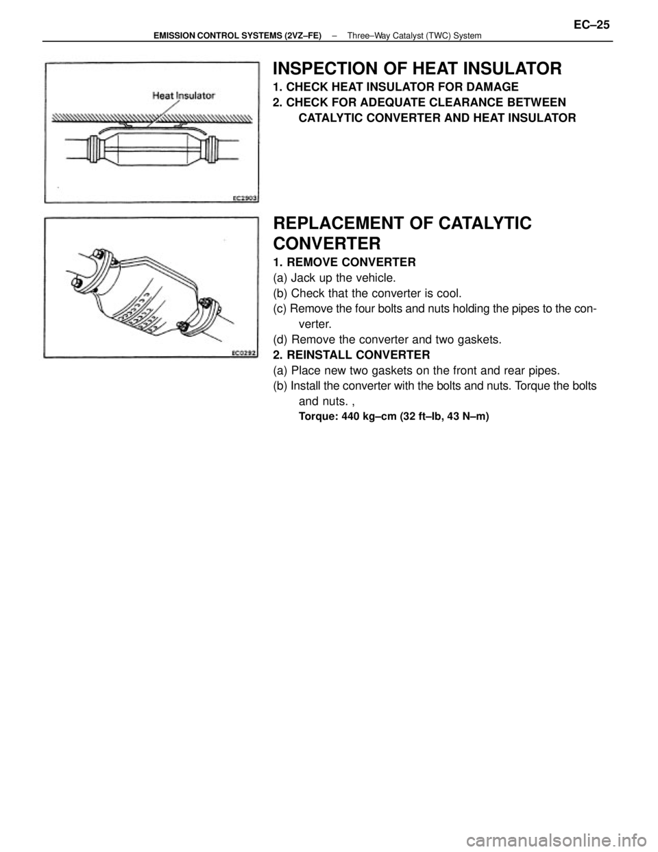
REPLACEMENT OF CATALYTIC
CONVERTER
1. REMOVE CONVERTER
(a) Jack up the vehicle.
(b) Check that the converter is cool.
(c) Remove the four bolts and nuts holding the pipes to the con-
verter.
(d) Remove the converter and two gaskets.
2. REINSTALL CONVERTER
(a) Place new two gaskets on the front and rear pipes.
(b) Install the converter with the bolts and nuts. Torque the bolts
and nuts. ,
Torque: 440 kg±cm (32 ft±Ib, 43 N±m)
INSPECTION OF HEAT INSULATOR
1. CHECK HEAT INSULATOR FOR DAMAGE
2. CHECK FOR ADEQUATE CLEARANCE BETWEEN
CATALYTIC CONVERTER AND HEAT INSULATOR
± EMISSION CONTROL SYSTEMS (2VZ±FE)Three±Way Catalyst (TWC) SystemEC±25
Page 1178 of 2389
ENGINE MECHANICAL
± ENGINE MECHANICALEM±1
Page 1179 of 2389
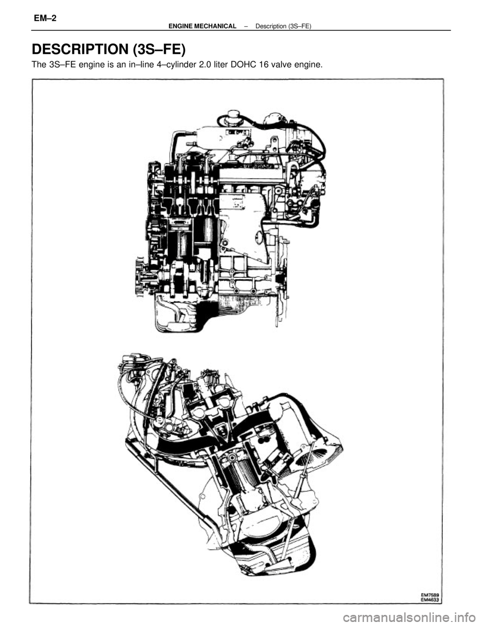
DESCRIPTION (3S±FE)
The 3S±FE engine is an in±line 4±cylinder 2.0 liter DOHC 16 valve engine.
± ENGINE MECHANICALDescription (3S±FE)EM±2
Page 1180 of 2389
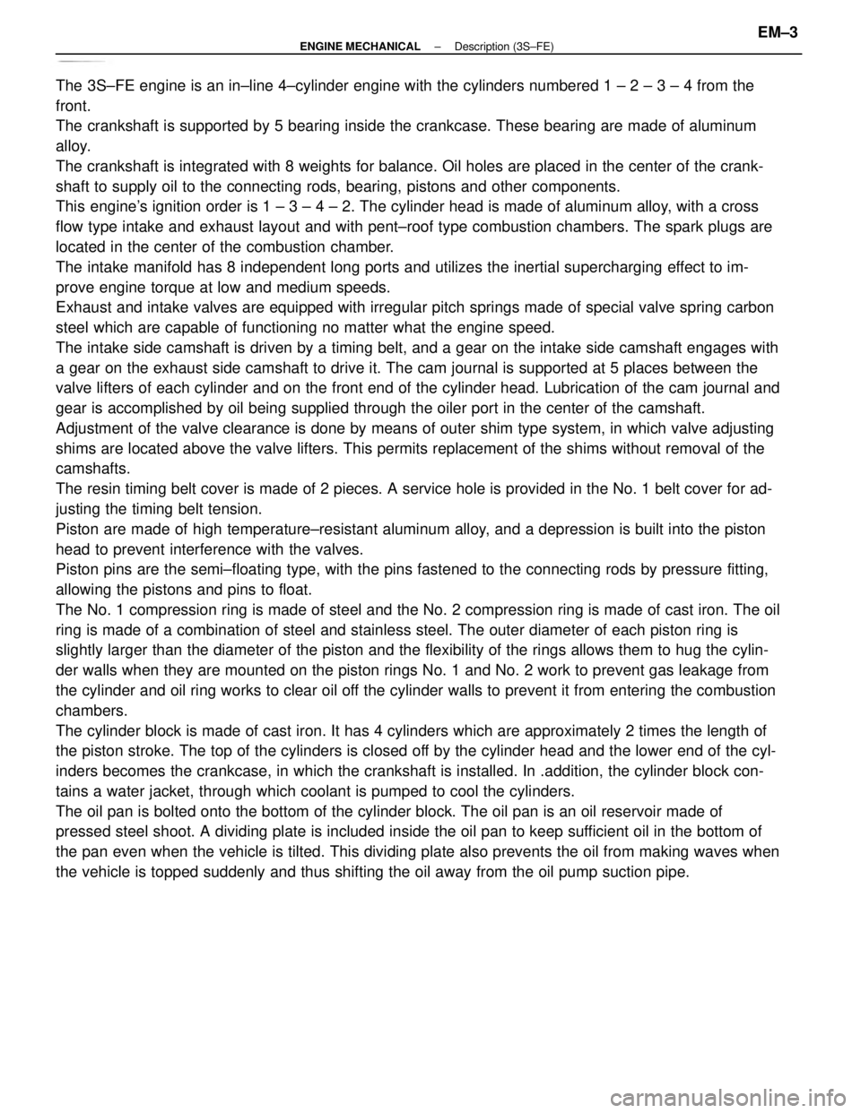
The 3S±FE engine is an in±line 4±cylinder engine with the cylinders numbered 1 ± 2 ± 3 ± 4 from the
front.
The crankshaft is supported by 5 bearing inside the crankcase. These bearing are made of aluminum
alloy.
The crankshaft is integrated with 8 weights for balance. Oil holes are placed in the center of the crank-
shaft to supply oil to the connecting rods, bearing, pistons and other components.
This engine's ignition order is 1 ± 3 ± 4 ± 2. The cylinder head is made of aluminum alloy, with a cross
flow type intake and exhaust layout and with pent±roof type combustion chambers. The spark plugs are
located in the center of the combustion chamber.
The intake manifold has 8 independent long ports and utilizes the inertial supercharging effect to im-
prove engine torque at low and medium speeds.
Exhaust and intake valves are equipped with irregular pitch springs made of special valve spring carbon
steel which are capable of functioning no matter what the engine speed.
The intake side camshaft is driven by a timing belt, and a gear on the intake side camshaft engages with
a gear on the exhaust side camshaft to drive it. The cam journal is supported at 5 places between the
valve lifters of each cylinder and on the front end of the cylinder head. Lubrication of the cam journal and
gear is accomplished by oil being supplied through the oiler port in the center of the camshaft.
Adjustment of the valve clearance is done by means of outer shim type system, in which valve adjusting
shims are located above the valve lifters. This permits replacement of the shims without removal of the
camshafts.
The resin timing belt cover is made of 2 pieces. A service hole is provided in the No. 1 belt cover for ad-
justing the timing belt tension.
Piston are made of high temperature±resistant aluminum alloy, and a depression is built into the piston
head to prevent interference with the valves.
Piston pins are the semi±floating type, with the pins fastened to the connecting rods by pressure fitting,
allowing the pistons and pins to float.
The No. 1 compression ring is made of steel and the No. 2 compression ring is made of cast iron. The oil
ring is made of a combination of steel and stainless steel. The outer diameter of each piston ring is
slightly larger than the diameter of the piston and the flexibility of the rings allows them to hug the cylin-
der walls when they are mounted on the piston rings No. 1 and No. 2 work to prevent gas leakage from
the cylinder and oil ring works to clear oil off the cylinder walls to prevent it from entering the combustion
chambers.
The cylinder block is made of cast iron. It has 4 cylinders which are approximately 2 times the length of
the piston stroke. The top of the cylinders is closed off by the cylinder head and the lower end of the cyl-
inders becomes the crankcase, in which the crankshaft is installed. In .addition, the cylinder block con-
tains a water jacket, through which coolant is pumped to cool the cylinders.
The oil pan is bolted onto the bottom of the cylinder block. The oil pan is an oil reservoir made of
pressed steel shoot. A dividing plate is included inside the oil pan to keep sufficient oil in the bottom of
the pan even when the vehicle is tilted. This dividing plate also prevents the oil from making waves when
the vehicle is topped suddenly and thus shifting the oil away from the oil pump suction pipe.
± ENGINE MECHANICALDescription (3S±FE)EM±3