TOYOTA CAMRY V20 1986 Service Information
CAMRY V20 1986
TOYOTA
TOYOTA
https://www.carmanualsonline.info/img/14/57449/w960_57449-0.png
TOYOTA CAMRY V20 1986 Service Information
Trending: check transmission fluid, tire type, spark plugs, headlights, fuel type, steering wheel adjustment, brake rotor
Page 2101 of 2389
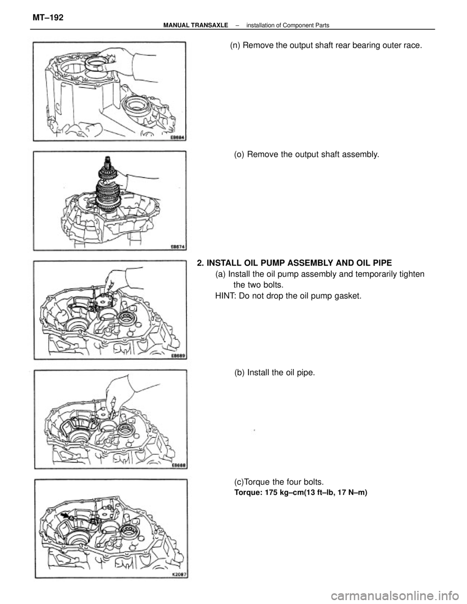
2. INSTALL OIL PUMP ASSEMBLY AND OIL PIPE
(a) Install the oil pump assembly and temporarily tighten
the two bolts.
HINT: Do not drop the oil pump gasket.(n) Remove the output shaft rear bearing outer race.
(c)Torque the four bolts.
Torque: 175 kg±cm(13 ft±lb, 17 N±m)
(o) Remove the output shaft assembly.
(b) Install the oil pipe.
± MANUAL TRANSAXLEinstallation of Component PartsMT±192
Page 2102 of 2389
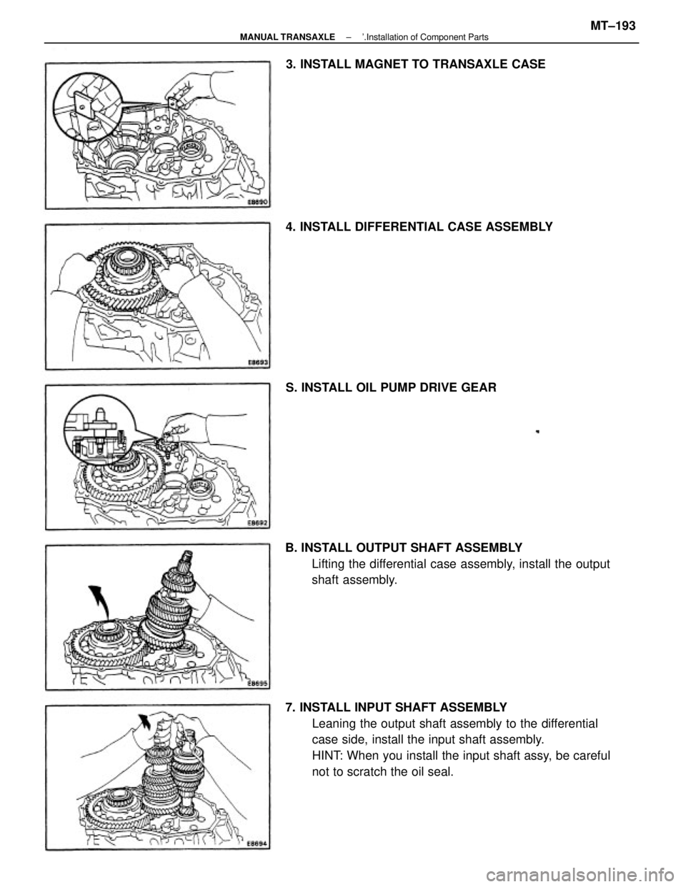
7. INSTALL INPUT SHAFT ASSEMBLY
Leaning the output shaft assembly to the differential
case side, install the input shaft assembly.
HINT: When you install the input shaft assy, be careful
not to scratch the oil seal. B. INSTALL OUTPUT SHAFT ASSEMBLY
Lifting the differential case assembly, install the output
shaft assembly. 4. INSTALL DIFFERENTIAL CASE ASSEMBLY3. INSTALL MAGNET TO TRANSAXLE CASE
S. INSTALL OIL PUMP DRIVE GEAR
± MANUAL TRANSAXLE'.Installation of Component PartsMT±193
Page 2103 of 2389
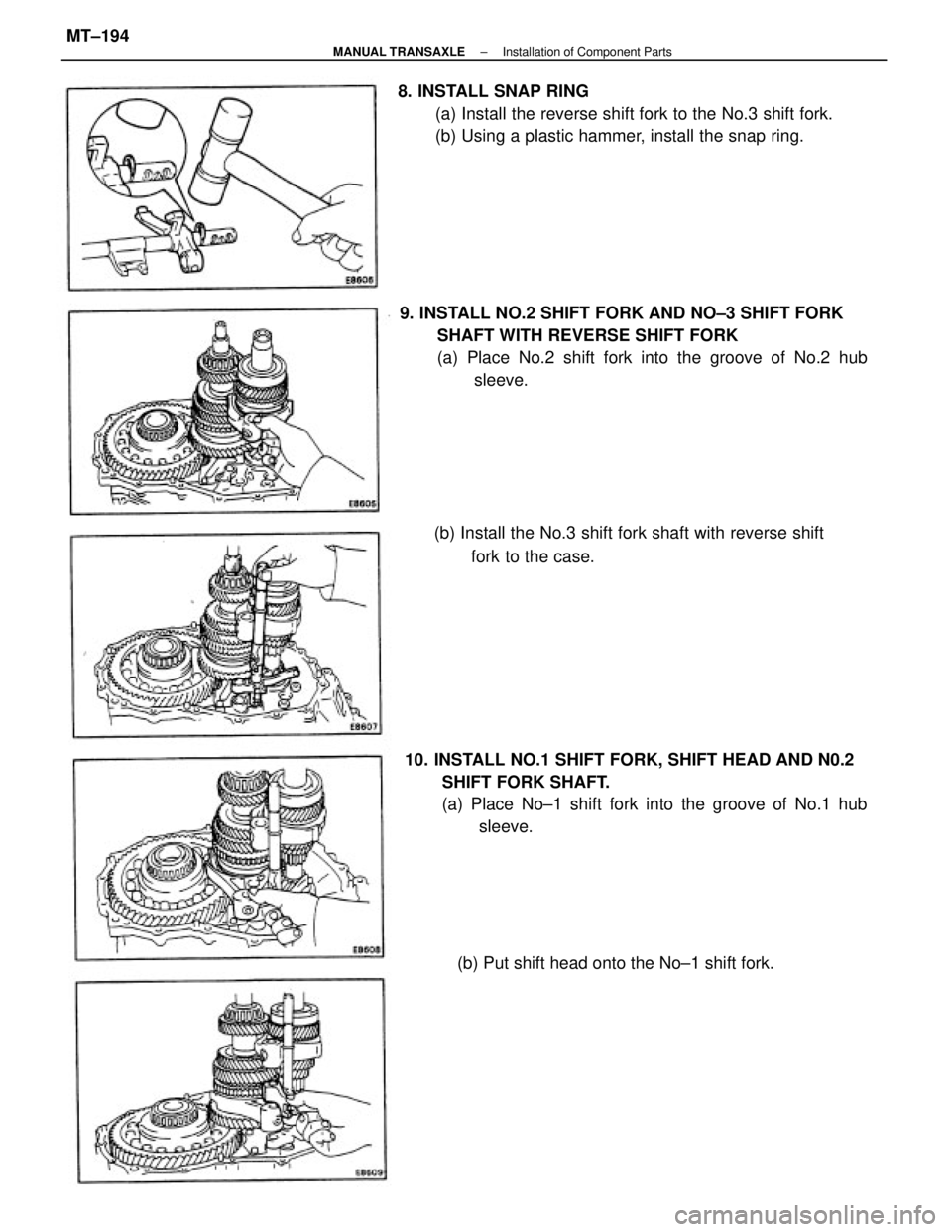
9. INSTALL NO.2 SHIFT FORK AND NO±3 SHIFT FORK
SHAFT WITH REVERSE SHIFT FORK
(a) Place No.2 shift fork into the groove of No.2 hub
sleeve.
10. INSTALL NO.1 SHIFT FORK, SHIFT HEAD AND N0.2
SHIFT FORK SHAFT.
(a) Place No±1 shift fork into the groove of No.1 hub
sleeve. 8. INSTALL SNAP RING
(a) Install the reverse shift fork to the No.3 shift fork.
(b) Using a plastic hammer, install the snap ring.
(b) Install the No.3 shift fork shaft with reverse shift
fork to the case.
(b) Put shift head onto the No±1 shift fork.
± MANUAL TRANSAXLEInstallation of Component PartsMT±194
Page 2104 of 2389
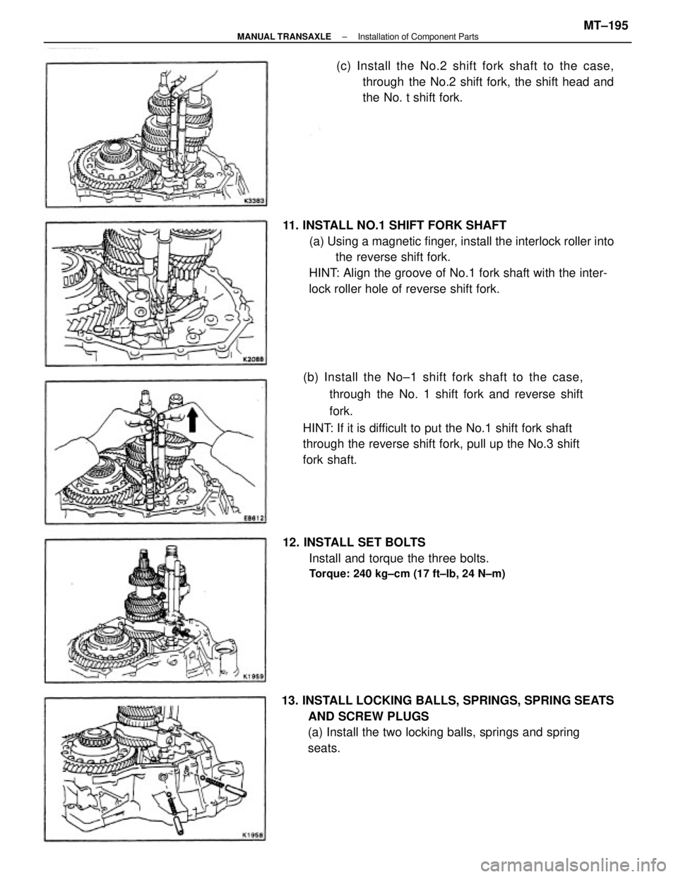
11. INSTALL NO.1 SHIFT FORK SHAFT
(a) Using a magnetic finger, install the interlock roller into
the reverse shift fork.
HINT: Align the groove of No.1 fork shaft with the inter-
lock roller hole of reverse shift fork.
(b) Install the No±1 shift fork shaft to the case,
through the No. 1 shift fork and reverse shift
fork.
HINT: If it is difficult to put the No.1 shift fork shaft
through the reverse shift fork, pull up the No.3 shift
fork shaft.
13. INSTALL LOCKING BALLS, SPRINGS, SPRING SEATS
AND SCREW PLUGS
(a) Install the two locking balls, springs and spring
seats.(c) Install the No.2 shift fork shaft to the case,
through the No.2 shift fork, the shift head and
the No. t shift fork.
12. INSTALL SET BOLTS
Install and torque the three bolts.
Torque: 240 kg±cm (17 ft±lb, 24 N±m)
± MANUAL TRANSAXLEInstallation of Component PartsMT±195
Page 2105 of 2389
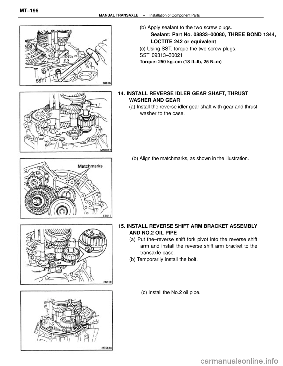
(b) Apply sealant to the two screw plugs.
Sealant: Part No. 08833±00080, THREE BOND 1344,
LOCTITE 242 or equivalent
(c) Using SST, torque the two screw plugs.
SST 09313±30021
Torque: 250 kg±cm (18 ft±Ib, 25 N±m)
15. INSTALL REVERSE SHIFT ARM BRACKET ASSEMBLY
AND NO.2 OIL PIPE
(a) Put the±reverse shift fork pivot into the reverse shift
arm and install the reverse shift arm bracket to the
transaxle case.
(b) Temporarily install the bolt. 14. INSTALL REVERSE IDLER GEAR SHAFT, THRUST
WASHER AND GEAR
(a) Install the reverse idler gear shaft with gear and thrust
washer to the case.
(b) Align the matchmarks, as shown in the illustration.
(c) Install the No.2 oil pipe.
± MANUAL TRANSAXLEInstallation of Component PartsMT±196
Page 2106 of 2389
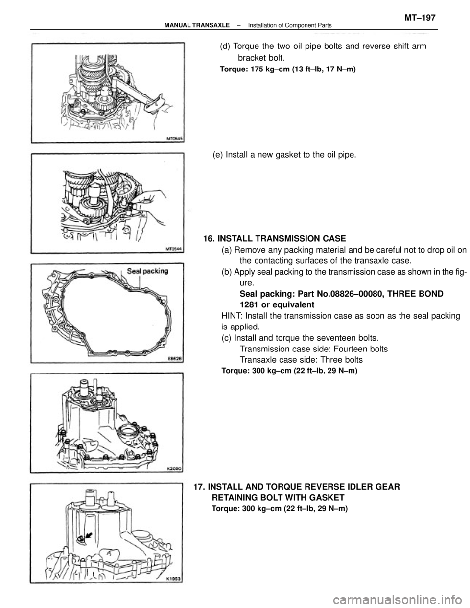
16. INSTALL TRANSMISSION CASE
(a) Remove any packing material and be careful not to drop oil on
the contacting surfaces of the transaxle case.
(b) Apply seal packing to the transmission case as shown in the fig-
ure.
Seal packing: Part No.08826±00080, THREE BOND
1281 or equivalent
HINT: Install the transmission case as soon as the seal packing
is applied.
(c) Install and torque the seventeen bolts.
Transmission case side: Fourteen bolts
Transaxle case side: Three bolts
Torque: 300 kg±cm (22 ft±Ib, 29 N±m)
(d) Torque the two oil pipe bolts and reverse shift arm
bracket bolt.
Torque: 175 kg±cm (13 ft±lb, 17 N±m)
17. INSTALL AND TORQUE REVERSE IDLER GEAR
RETAINING BOLT WITH GASKET
Torque: 300 kg±cm (22 ft±Ib, 29 N±m)
(e) Install a new gasket to the oil pipe.
± MANUAL TRANSAXLEInstallation of Component PartsMT±197
Page 2107 of 2389
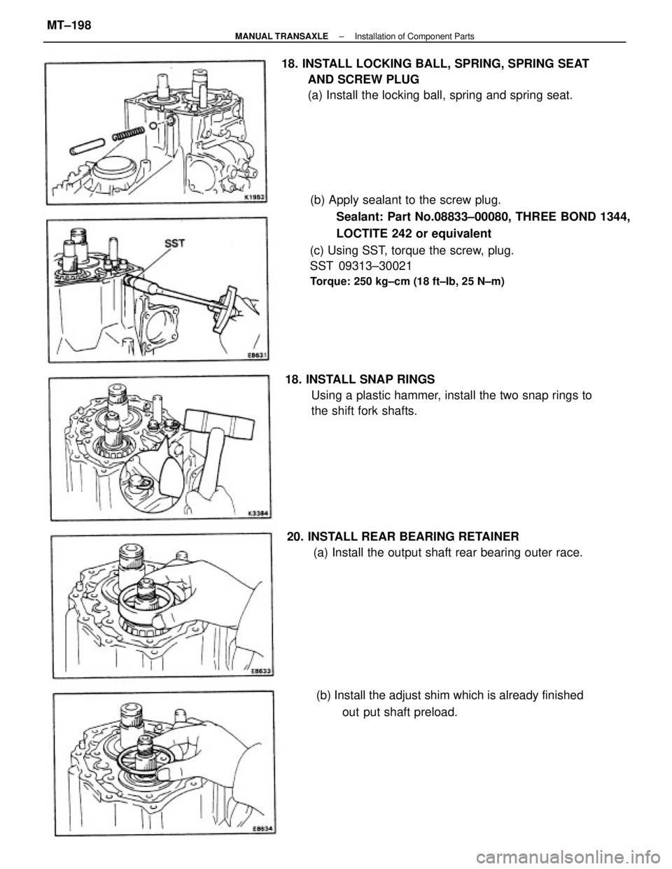
(b) Apply sealant to the screw plug.
Sealant: Part No.08833±00080, THREE BOND 1344,
LOCTITE 242 or equivalent
(c) Using SST, torque the screw, plug.
SST 09313±30021
Torque: 250 kg±cm (18 ft±Ib, 25 N±m)
18. INSTALL LOCKING BALL, SPRING, SPRING SEAT
AND SCREW PLUG
(a) Install the locking ball, spring and spring seat.
18. INSTALL SNAP RINGS
Using a plastic hammer, install the two snap rings to
the shift fork shafts.
20. INSTALL REAR BEARING RETAINER
(a) Install the output shaft rear bearing outer race.
(b) Install the adjust shim which is already finished
out put shaft preload.
± MANUAL TRANSAXLEInstallation of Component PartsMT±198
Page 2108 of 2389
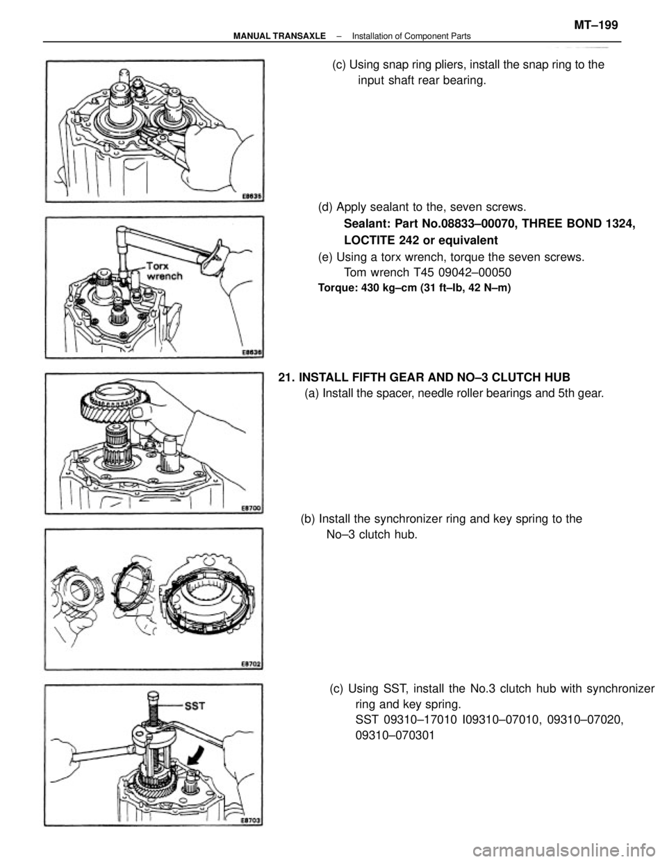
(d) Apply sealant to the, seven screws.
Sealant: Part No.08833±00070, THREE BOND 1324,
LOCTITE 242 or equivalent
(e) Using a torx wrench, torque the seven screws.
Tom wrench T45 09042±00050
Torque: 430 kg±cm (31 ft±Ib, 42 N±m)
(c) Using SST, install the No.3 clutch hub with synchronizer
ring and key spring.
SST 09310±17010 I09310±07010, 09310±07020,
09310±070301 21. INSTALL FIFTH GEAR AND NO±3 CLUTCH HUB
(a) Install the spacer, needle roller bearings and 5th gear.
(b) Install the synchronizer ring and key spring to the
No±3 clutch hub.(c) Using snap ring pliers, install the snap ring to the
input shaft rear bearing.
± MANUAL TRANSAXLEInstallation of Component PartsMT±199
Page 2109 of 2389
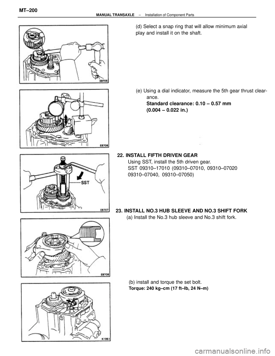
22. INSTALL FIFTH DRIVEN GEAR
Using SST, install the 5th driven gear.
SST 09310±17010 (09310±07010, 09310±07020
09310±07040, 09310±07050)(e) Using a dial indicator, measure the 5th gear thrust clear-
ance.
Standard clearance: 0.10 ± 0.57 mm
(0.004 ± 0.022 in.)
23. INSTALL NO.3 HUB SLEEVE AND NO.3 SHIFT FORK
(a) Install the No.3 hub sleeve and No.3 shift fork.(d) Select a snap ring that will allow minimum axial
play and install it on the shaft.
(b) install and torque the set bolt.
Torque: 240 kg±cm (17 ft±Ib, 24 N±m)
± MANUAL TRANSAXLEInstallation of Component PartsMT±200
Page 2110 of 2389
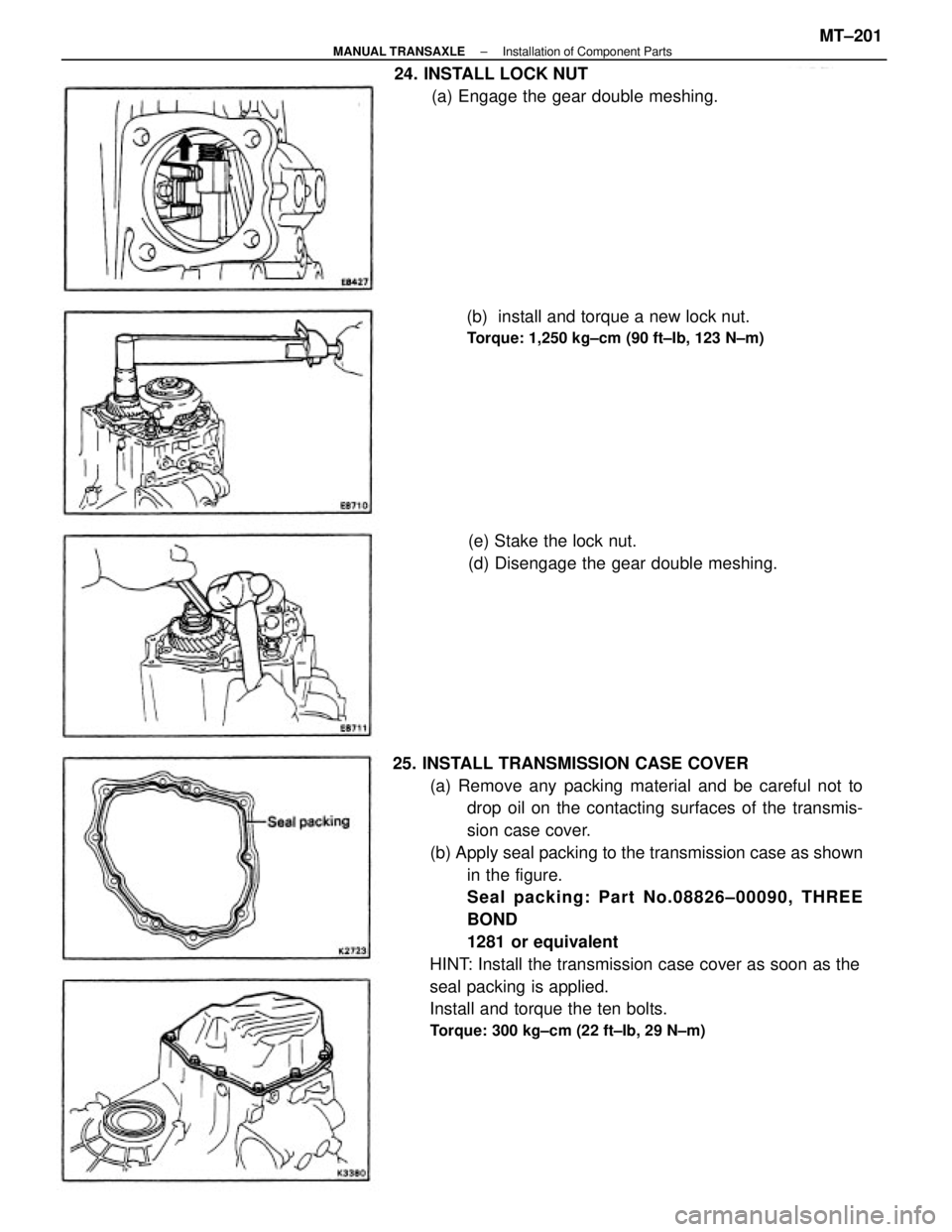
25. INSTALL TRANSMISSION CASE COVER
(a) Remove any packing material and be careful not to
drop oil on the contacting surfaces of the transmis-
sion case cover.
(b) Apply seal packing to the transmission case as shown
in the figure.
Seal packing: Part No.08826±00090, THREE
BOND
1281 or equivalent
HINT: Install the transmission case cover as soon as the
seal packing is applied.
Install and torque the ten bolts.
Torque: 300 kg±cm (22 ft±Ib, 29 N±m)
24. INSTALL LOCK NUT
(a) Engage the gear double meshing.
(b) install and torque a new lock nut.
Torque: 1,250 kg±cm (90 ft±Ib, 123 N±m)
(e) Stake the lock nut.
(d) Disengage the gear double meshing.
± MANUAL TRANSAXLEInstallation of Component PartsMT±201
Trending: wiper fluid, manual radio set, boot, brake, spark plugs replace, brake fluid, service schedule
