TOYOTA CAMRY V20 1986 Service Information
CAMRY V20 1986
TOYOTA
TOYOTA
https://www.carmanualsonline.info/img/14/57449/w960_57449-0.png
TOYOTA CAMRY V20 1986 Service Information
Trending: heating, flat tire, remove seats, ECU, seat adjustment, fuel pump, trunk release
Page 2131 of 2389
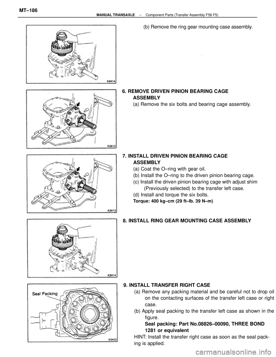
9. INSTALL TRANSFER RIGHT CASE
(a) Remove any packing material and be careful not to drop oil
on the contacting surfaces of the transfer left case or right
case.
(b) Apply seal packing to the transfer left case as shown in the
figure.
Seal packing: Part No.08826±00090, THREE BOND
1281 or equivalent
HINT: Install the transfer right case as soon as the seal pack-
ing is applied. 7. INSTALL DRIVEN PINION BEARING CAGE
ASSEMBLY
(a) Coat the O±ring with gear oil.
(b) Install the O±ring to the driven pinion bearing cage.
(c) Install the driven pinion bearing cage with adjust shim
(Previously selected) to the transfer left case.
(d) Install and torque the six bolts.
Torque: 400 kg±cm (29 ft±Ib. 39 N±m)
6. REMOVE DRIVEN PINION BEARING CAGE
ASSEMBLY
(a) Remove the six bolts and bearing cage assembly.
8. INSTALL RING GEAR MOUNTING CASE ASSEMBLY(b) Remove the ring gear mounting case assembly.
± MANUAL TRANSAXLEComponent Parts (Transfer Assembly F56 F5)MT±186
Page 2132 of 2389
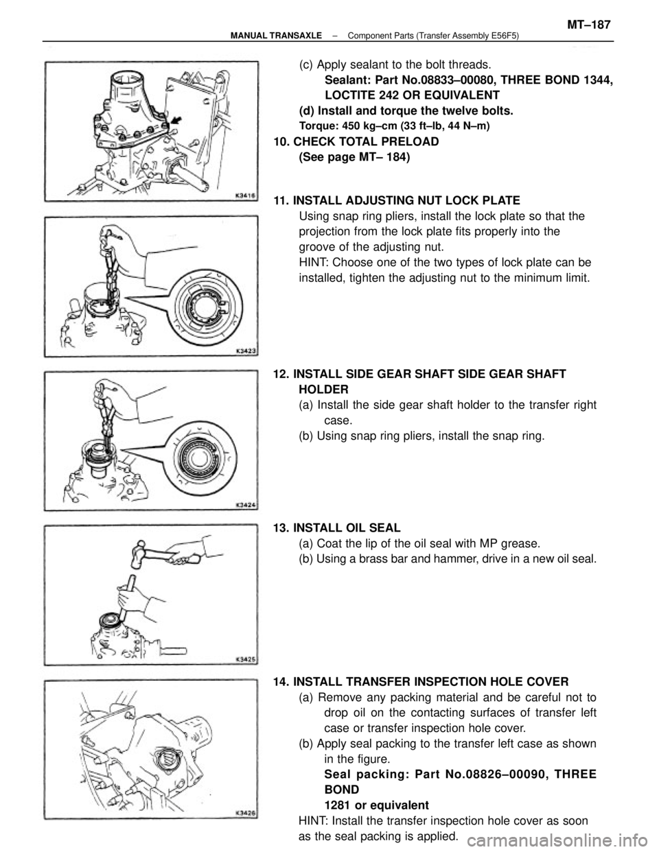
14. INSTALL TRANSFER INSPECTION HOLE COVER
(a) Remove any packing material and be careful not to
drop oil on the contacting surfaces of transfer left
case or transfer inspection hole cover.
(b) Apply seal packing to the transfer left case as shown
in the figure.
Seal packing: Part No.08826±00090, THREE
BOND
1281 or equivalent
HINT: Install the transfer inspection hole cover as soon
as the seal packing is applied.(c) Apply sealant to the bolt threads.
Sealant: Part No.08833±00080, THREE BOND 1344,
LOCTITE 242 OR EQUIVALENT
(d) Install and torque the twelve bolts.
Torque: 450 kg±cm (33 ft±lb, 44 N±m)
10. CHECK TOTAL PRELOAD
(See page MT± 184)
11. INSTALL ADJUSTING NUT LOCK PLATE
Using snap ring pliers, install the lock plate so that the
projection from the lock plate fits properly into the
groove of the adjusting nut.
HINT: Choose one of the two types of lock plate can be
installed, tighten the adjusting nut to the minimum limit.
12. INSTALL SIDE GEAR SHAFT SIDE GEAR SHAFT
HOLDER
(a) Install the side gear shaft holder to the transfer right
case.
(b) Using snap ring pliers, install the snap ring.
13. INSTALL OIL SEAL
(a) Coat the lip of the oil seal with MP grease.
(b) Using a brass bar and hammer, drive in a new oil seal.
± MANUAL TRANSAXLEComponent Parts (Transfer Assembly E56F5)MT±187
Page 2133 of 2389
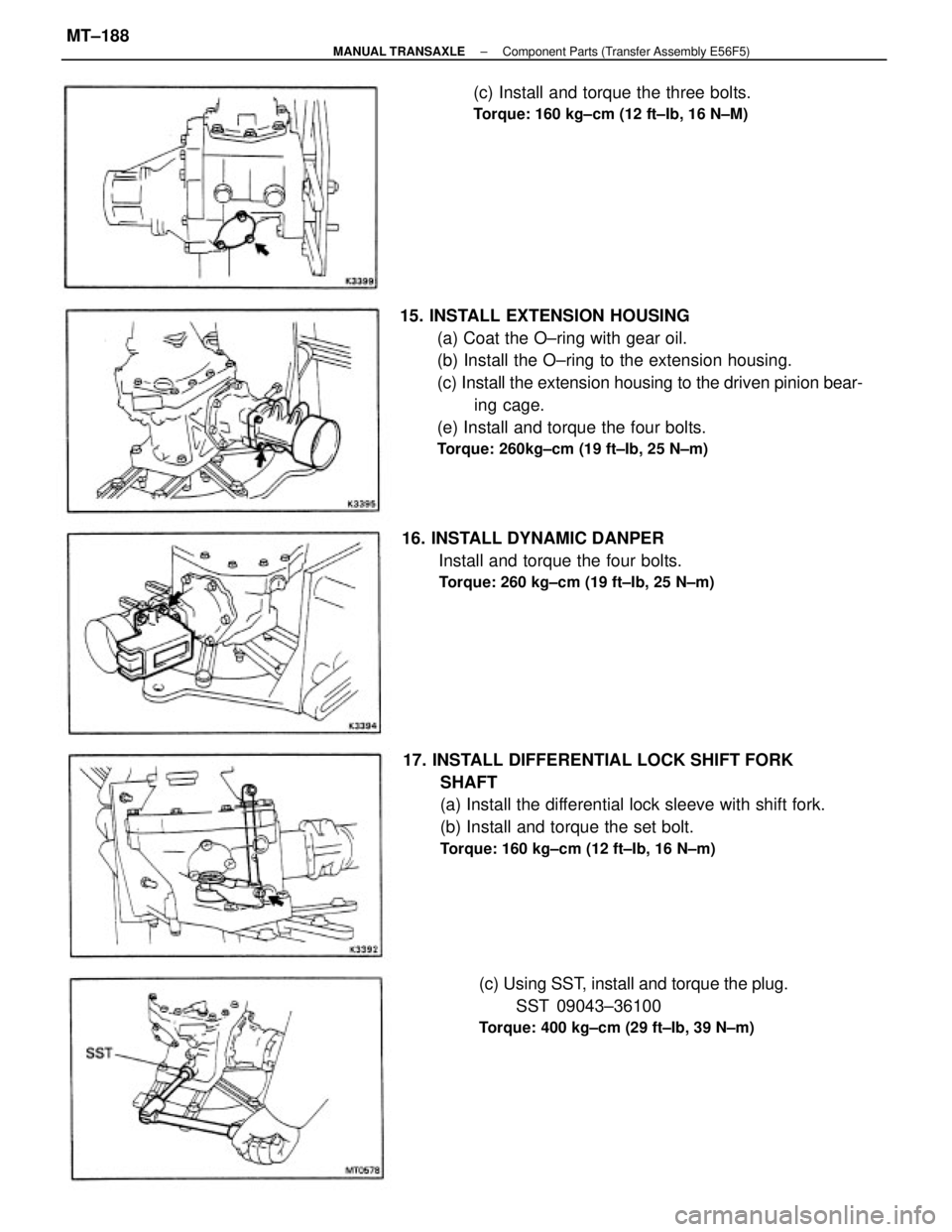
15. INSTALL EXTENSION HOUSING
(a) Coat the O±ring with gear oil.
(b) Install the O±ring to the extension housing.
(c) Install the extension housing to the driven pinion bear-
ing cage.
(e) Install and torque the four bolts.
Torque: 260kg±cm (19 ft±Ib, 25 N±m)
17. INSTALL DIFFERENTIAL LOCK SHIFT FORK
SHAFT
(a) Install the differential lock sleeve with shift fork.
(b) Install and torque the set bolt.
Torque: 160 kg±cm (12 ft±Ib, 16 N±m)
16. INSTALL DYNAMIC DANPER
Install and torque the four bolts.
Torque: 260 kg±cm (19 ft±Ib, 25 N±m)
(c) Using SST, install and torque the plug.
SST 09043±36100
Torque: 400 kg±cm (29 ft±Ib, 39 N±m)
(c) Install and torque the three bolts.
Torque: 160 kg±cm (12 ft±Ib, 16 N±M)
± MANUAL TRANSAXLEComponent Parts (Transfer Assembly E56F5)MT±188
Page 2134 of 2389
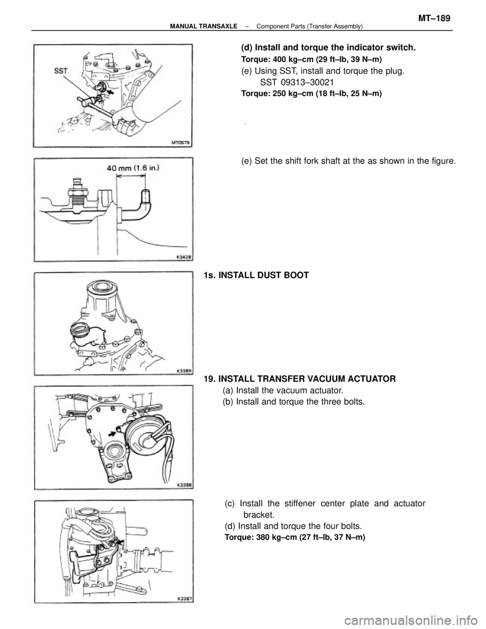
19. INSTALL TRANSFER VACUUM ACTUATOR
(a) Install the vacuum actuator.
(b) Install and torque the three bolts.(d) Install and torque the indicator switch.
Torque: 400 kg±cm (29 ft±Ib, 39 N±m)
(e) Using SST, install and torque the plug.
SST 09313±30021
Torque: 250 kg±cm (18 ft±Ib, 25 N±m)
(c) Install the stiffener center plate and actuator
bracket.
(d) Install and torque the four bolts.
Torque: 380 kg±cm (27 ft±lb, 37 N±m)
(e) Set the shift fork shaft at the as shown in the figure.
1s. INSTALL DUST BOOT
± MANUAL TRANSAXLEComponent Parts (Transfer Assembly)MT±189
Page 2135 of 2389
PROPELLER SHAFT
PROPELLER SHAFTPR±1
Page 2136 of 2389
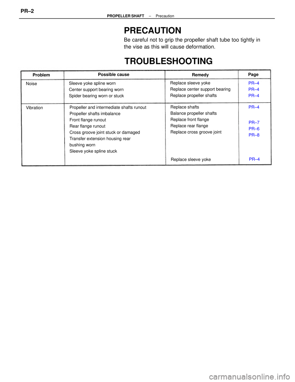
Propeller and intermediate shafts runout
Propeller shafts imbalance
Front flange runout
Rear flange runout
Cross groove joint stuck or damaged
Transfer extension housing rear
bushing worn
Sleeve yoke spline stuck
PRECAUTION
Be careful not to grip the propeller shaft tube too tightly in
the vise as this will cause deformation.
Replace shafts
Balance propeller shafts
Replace front flange
Replace rear flange
Replace cross groove joint Replace sleeve yoke
Replace center support bearing
Replace propeller shafts Sleeve yoke spline worn
Center support bearing worn
Spider bearing worn or stuck
TROUBLESHOOTING
Replace sleeve yokePR±4
PR±4
PR±4
PR±7
PR±6
PR±8 Possible cause
VibrationProblemRemedy
NoisePage
PR±4
PR±4
± PROPELLER SHAFTPrecautionPR±2
Page 2137 of 2389
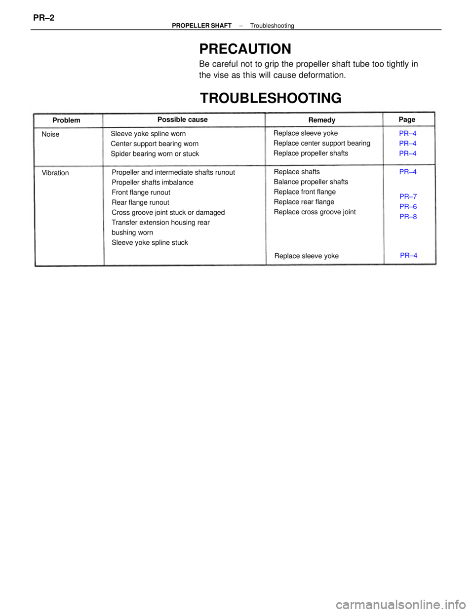
Propeller and intermediate shafts runout
Propeller shafts imbalance
Front flange runout
Rear flange runout
Cross groove joint stuck or damaged
Transfer extension housing rear
bushing worn
Sleeve yoke spline stuck
PRECAUTION
Be careful not to grip the propeller shaft tube too tightly in
the vise as this will cause deformation.
Replace shafts
Balance propeller shafts
Replace front flange
Replace rear flange
Replace cross groove joint Replace sleeve yoke
Replace center support bearing
Replace propeller shafts Sleeve yoke spline worn
Center support bearing worn
Spider bearing worn or stuck
TROUBLESHOOTING
Replace sleeve yokePR±4
PR±4
PR±4
PR±7
PR±6
PR±8 Possible cause
VibrationProblemRemedy
NoisePage
PR±4
PR±4
± PROPELLER SHAFTTroubleshootingPR±2
Page 2138 of 2389
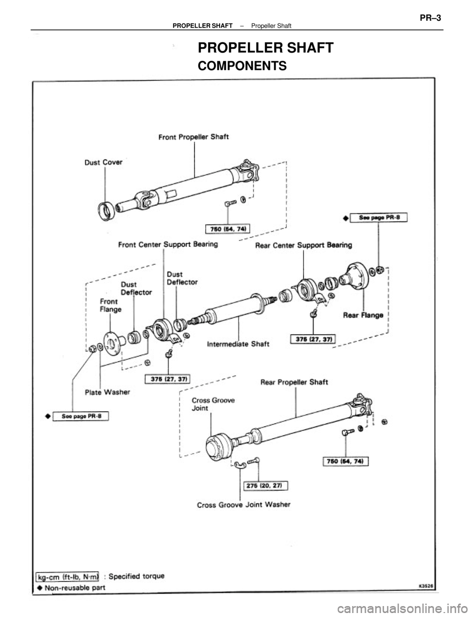
PROPELLER SHAFT
COMPONENTS
± PROPELLER SHAFTPropeller ShaftPR±3
Page 2139 of 2389
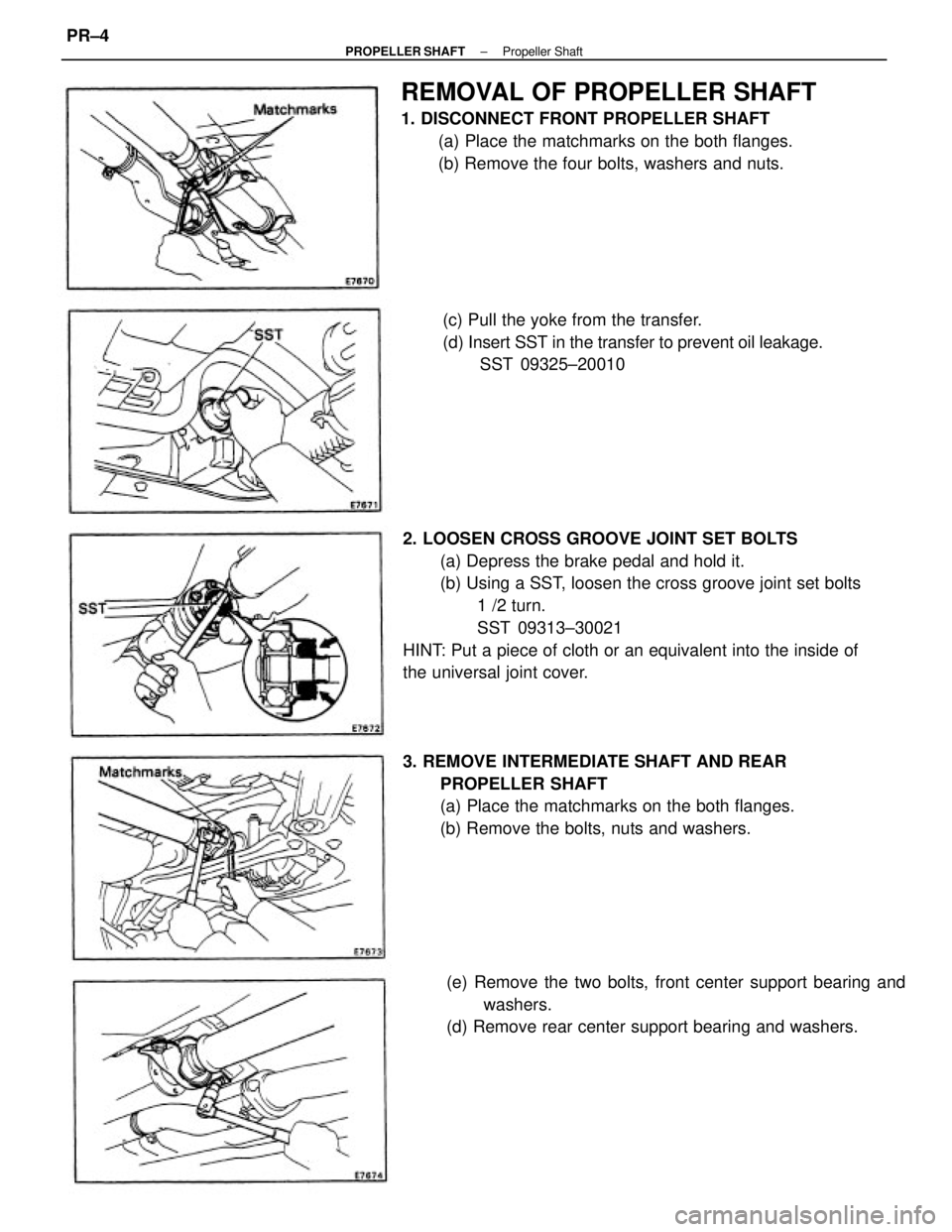
2. LOOSEN CROSS GROOVE JOINT SET BOLTS
(a) Depress the brake pedal and hold it.
(b) Using a SST, loosen the cross groove joint set bolts
1 /2 turn.
SST 09313±30021
HINT: Put a piece of cloth or an equivalent into the inside of
the universal joint cover.
REMOVAL OF PROPELLER SHAFT
1. DISCONNECT FRONT PROPELLER SHAFT
(a) Place the matchmarks on the both flanges.
(b) Remove the four bolts, washers and nuts.
3. REMOVE INTERMEDIATE SHAFT AND REAR
PROPELLER SHAFT
(a) Place the matchmarks on the both flanges.
(b) Remove the bolts, nuts and washers.
(e) Remove the two bolts, front center support bearing and
washers.
(d) Remove rear center support bearing and washers. (c) Pull the yoke from the transfer.
(d) Insert SST in the transfer to prevent oil leakage.
SST 09325±20010
± PROPELLER SHAFTPropeller ShaftPR±4
Page 2140 of 2389
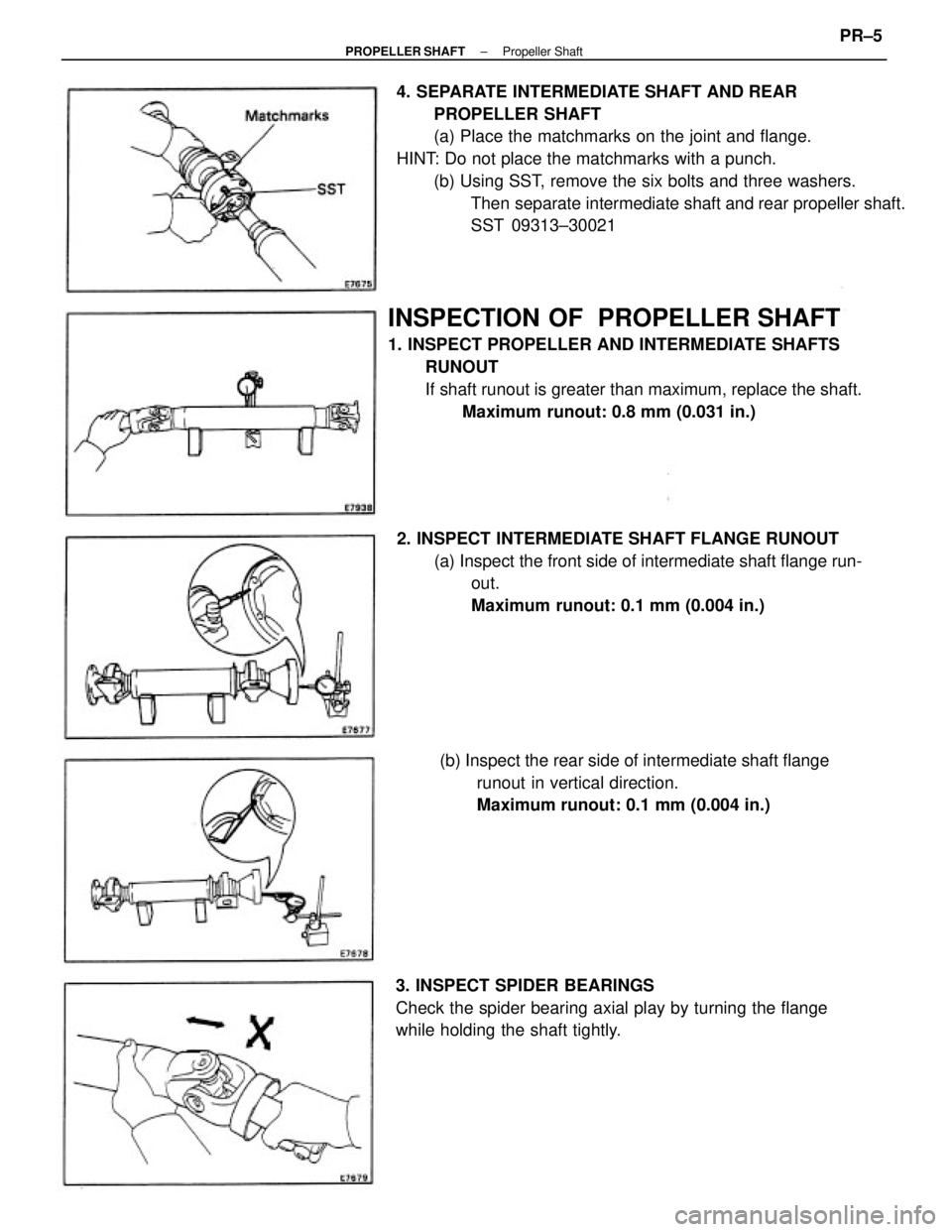
4. SEPARATE INTERMEDIATE SHAFT AND REAR
PROPELLER SHAFT
(a) Place the matchmarks on the joint and flange.
HINT: Do not place the matchmarks with a punch.
(b) Using SST, remove the six bolts and three washers.
Then separate intermediate shaft and rear propeller shaft.
SST 09313±30021
INSPECTION OF PROPELLER SHAFT
1. INSPECT PROPELLER AND INTERMEDIATE SHAFTS
RUNOUT
If shaft runout is greater than maximum, replace the shaft.
Maximum runout: 0.8 mm (0.031 in.)
2. INSPECT INTERMEDIATE SHAFT FLANGE RUNOUT
(a) Inspect the front side of intermediate shaft flange run-
out.
Maximum runout: 0.1 mm (0.004 in.)
(b) Inspect the rear side of intermediate shaft flange
runout in vertical direction.
Maximum runout: 0.1 mm (0.004 in.)
3. INSPECT SPIDER BEARINGS
Check the spider bearing axial play by turning the flange
while holding the shaft tightly.
± PROPELLER SHAFTPropeller ShaftPR±5
Trending: roof, check transmission fluid, clock reset, fuel cap, parking brake, trunk, open hood
