TOYOTA CAMRY V20 1986 Service Information
Manufacturer: TOYOTA, Model Year: 1986, Model line: CAMRY V20, Model: TOYOTA CAMRY V20 1986Pages: 2389, PDF Size: 84.44 MB
Page 211 of 2389
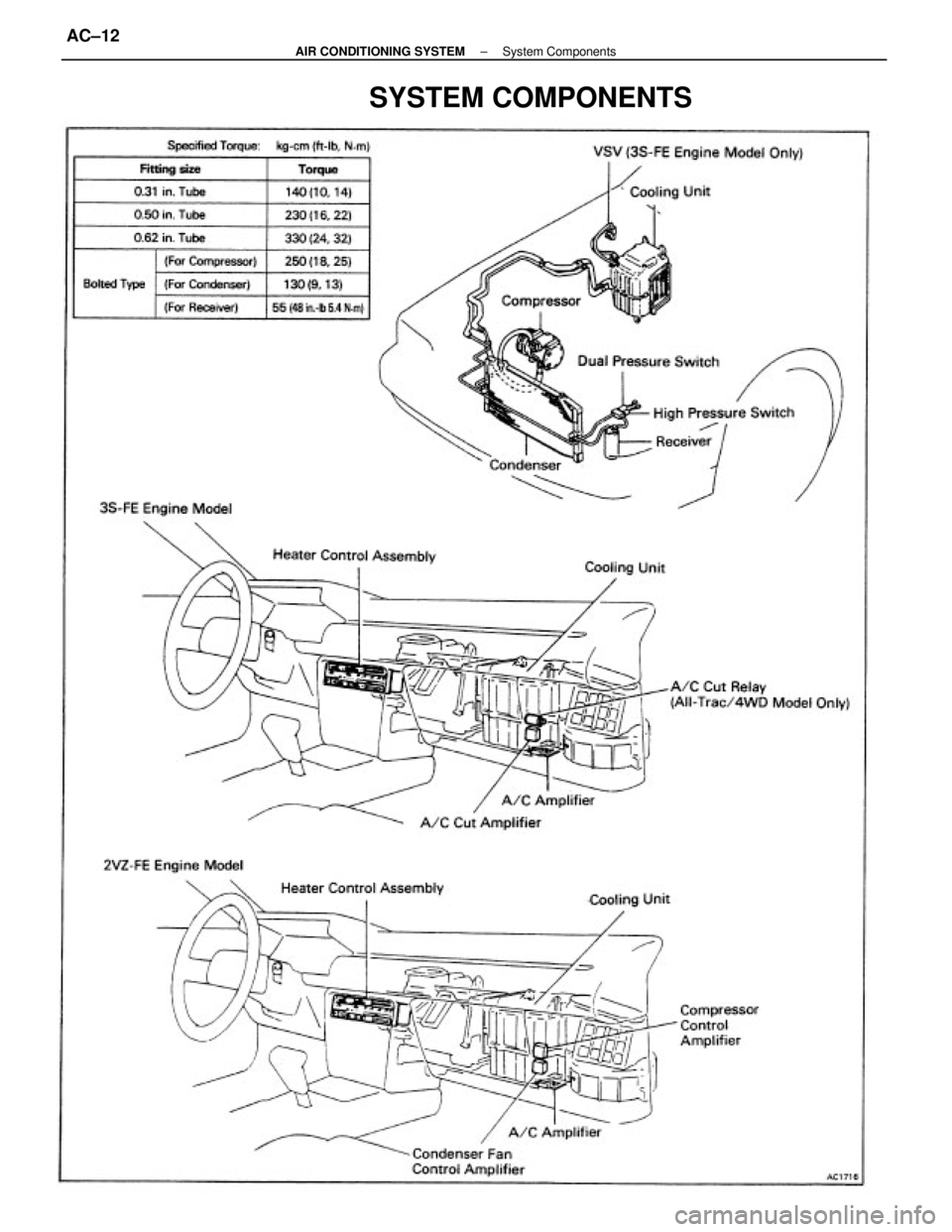
SYSTEM COMPONENTS
± AIR CONDITIONING SYSTEMSystem ComponentsAC±12
Page 212 of 2389
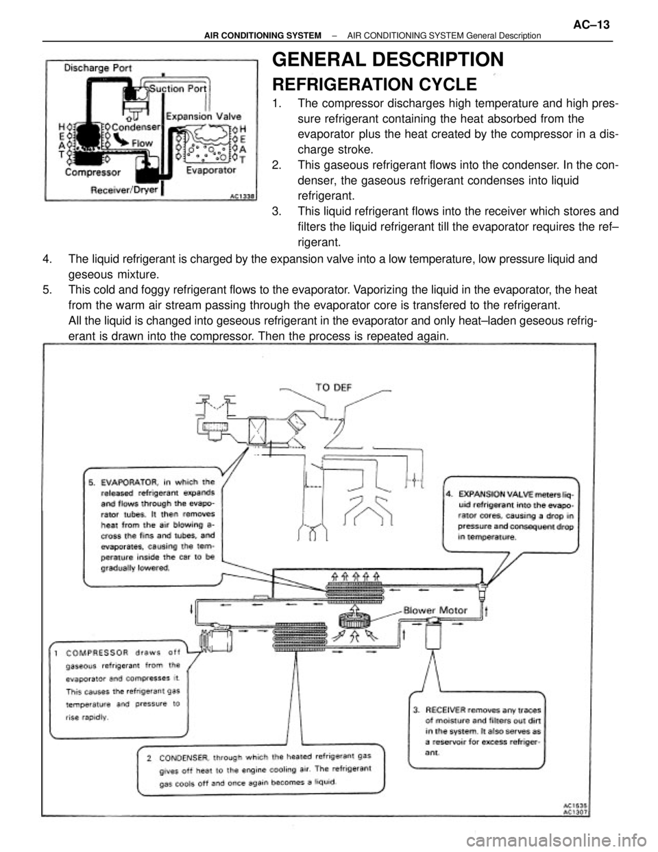
4. The liquid refrigerant is charged by the expansion valve into a low temperature, low pressure liquid and
geseous mixture.
5. This cold and foggy refrigerant flows to the evaporator. Vaporizing the liquid in the evaporator, the heat
from the warm air stream passing through the evaporator core is transfered to the refrigerant.
All the liquid is changed into geseous refrigerant in the evaporator and only heat±laden geseous refrig-
erant is drawn into the compressor. Then the process is repeated again.
GENERAL DESCRIPTION
REFRIGERATION CYCLE
1. The compressor discharges high temperature and high pres-
sure refrigerant containing the heat absorbed from the
evaporator plus the heat created by the compressor in a dis-
charge stroke.
2. This gaseous refrigerant flows into the condenser. In the con-
denser, the gaseous refrigerant condenses into liquid
refrigerant.
3. This liquid refrigerant flows into the receiver which stores and
filters the liquid refrigerant till the evaporator requires the ref±
rigerant.
± AIR CONDITIONING SYSTEMAIR CONDITIONING SYSTEM General DescriptionAC±13
Page 213 of 2389
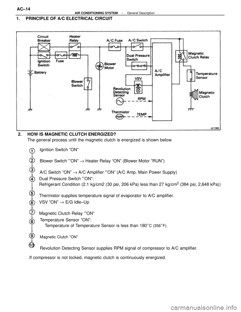
Ignition Switch ºONº
Blower Switch º'ONº " Heater Relay ªONº (Blower Motor ºRUNº)
A/C Switch ºONº " A/C Amplifier º'ONº (A/C Amp. Main Power Supply) 1. PRINCIPLE OF A/C ELECTRICAL CIRCUIT
2. HOW IS MAGNETIC CLUTCH ENERGIZED?
The general process until the magnetic clutch is energized is shown below.
Dual Pressure Switch º'ONº:
Refrigerant Condition (2.1 kg/cm2 (30 psi, 206 kPa) less than 27 kg/cm
2 (384 psi, 2,648 kPa))
Thermistor supplies temperature signal of evaporator to A/C amplifier.
VSV ºONº " E/G Idle±Up
Magnetic Clutch Relay º'ONº
Temperature Sensor ºONº:
Temperature of Temperature Sensor is less than 180
°C (356°F).
Magnetic Clutch ºONº
Revolution Detecting Sensor supplies RPM signal of compressor to A/C amplifier.
If compressor is not locked, magnetic clutch is continuously energized.
± AIR CONDITIONING SYSTEMGeneral DescriptionAC±14
Page 214 of 2389
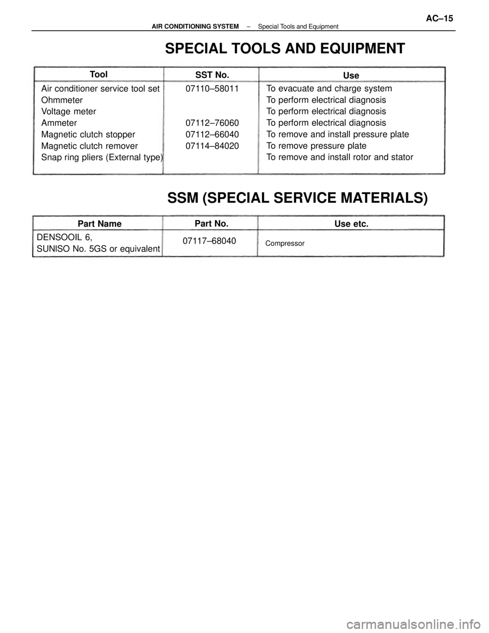
To evacuate and charge system
To perform electrical diagnosis
To perform electrical diagnosis
To perform electrical diagnosis
To remove and install pressure plate
To remove pressure plate
To remove and install rotor and stator Air conditioner service tool set
Ohmmeter
Voltage meter
Ammeter
Magnetic clutch stopper
Magnetic clutch remover
Snap ring pliers (External type)
SPECIAL TOOLS AND EQUIPMENT
SSM (SPECIAL SERVICE MATERIALS)
07110±58011
07112±76060
07112±66040
07114±84020
DENSOOIL 6,
SUNlSO No. 5GS or equivalent07117±68040
Compressor
Part NameSST No.
Part No.
Use etc. Tool
Use
± AIR CONDITIONING SYSTEMSpecial Tools and EquipmentAC±15
Page 215 of 2389
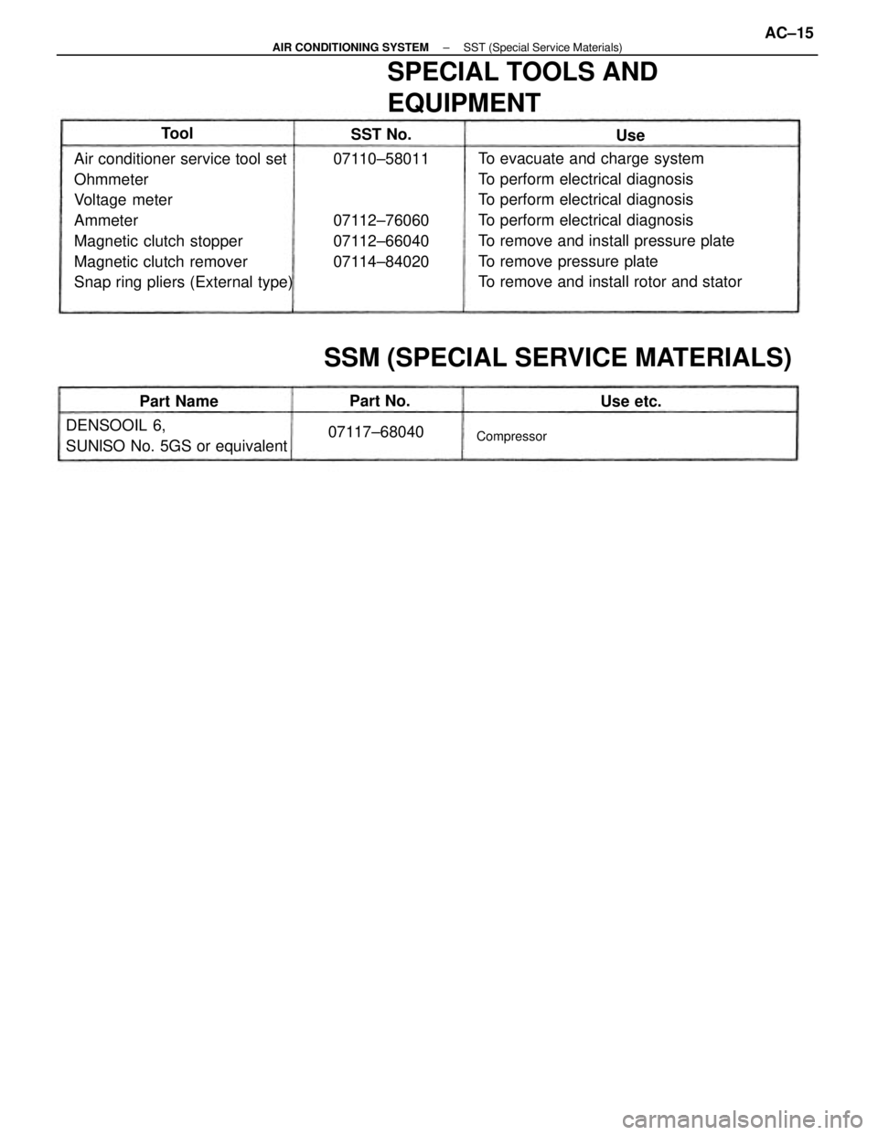
To evacuate and charge system
To perform electrical diagnosis
To perform electrical diagnosis
To perform electrical diagnosis
To remove and install pressure plate
To remove pressure plate
To remove and install rotor and stator Air conditioner service tool set
Ohmmeter
Voltage meter
Ammeter
Magnetic clutch stopper
Magnetic clutch remover
Snap ring pliers (External type)
SPECIAL TOOLS AND
EQUIPMENT
SSM (SPECIAL SERVICE MATERIALS)
07110±58011
07112±76060
07112±66040
07114±84020
DENSOOIL 6,
SUNlSO No. 5GS or equivalent07117±68040
Compressor
Part NameSST No.
Part No.
Use etc. Tool
Use
± AIR CONDITIONING SYSTEMSST (Special Service Materials)AC±15
Page 216 of 2389
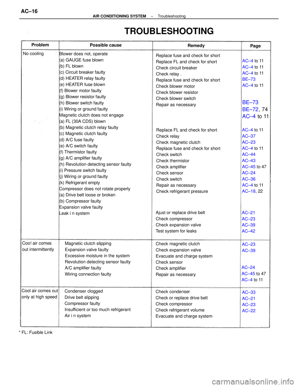
Blower does not, operate
(a) GAUGE fuse blown
(b) FL blown
(c) Circuit breaker faulty
(d) HEATER relay faulty
(e) HEATER fuse blown
(f) Blower motor faulty
(g) Blower resistor faulty
(h) Blower switch faulty
(i) Wiring or ground faulty
Magnetic clutch does not engage
(a) FL (30A CDS) blown
(b) Magnetic clutch relay faulty
(c) Magnetic clutch faulty
(d) A/C fuse faulty
(e) A/C switch faulty
(f) Thermistor faulty
(g) A/C amplifier faulty
(h) Revolution detecting sensor faulty
(i) Pressure switch faulty
(j) Wiring or ground faulty
(k) Refrigerant empty
Compressor does not rotate properly
(a) Drive belt loose or broken
(b) Compressor faulty
Expansion valve faulty
Leak i n systemReplace FL and check for short
Check relay
Check magnetic clutch
Replace fuse and check for short
Check switch
Check thermistor
Check amplifier
Check sensor
Check switch
Repair as necessary
Check refrigerant pressure Replace fuse and check for short
Replace FL and check for short
Check circuit breaker
Check relay .
Replace fuse and check for short
Check blower motor
Check blower resistor
Check blower switch
Repair as necessary
Magnetic clutch slipping
Expansion valve faulty
Excessive moisture in the system
Revolution detecting sensor faulty
A/C amplifier faulty
Wiring connection faulty
Condenser clogged
Drive belt slipping
Compressor faulty
Insufficient or too much refrigerant
Air i n systemCheck magnetic clutch
Check expansion valve
Evacuate and charge system
Check sensor
Check amplifier
Repair as necessary
Check condenser
Check or replace drive belt
Check compressor
Check refrigerant volume
Evacuate and charge systemAC±4 to 11
AC±37
AC±23
AC±4 to 11
AC±44
AC±43
AC±45 to 47
AC±24
AC±36
AC±4 to 11
AC±18, 22
Ajust or replace drive belt
Check compressor
Check expansion valve
Test system for leaks
TROUBLESHOOTING
AC±4 to 11
AC±4 to 11
AC±4 to 11
BE±73
AC±4 to 11
Cool air comes out
only at high speedAC±24
AC±45 to 47
AC±4 to 11 Coo! air comes
out intermittently
BE±73
BE±72, 74
AC±4 to 11
AC±33
AC±21
AC±23
AC±22 AC±21
AC±23
AC±39
AC±42
* FL: Fusible LinkPossible cause
AC±23
AC±39 No coolingRemedy Problem
Page
± AIR CONDITIONING SYSTEMTroubleshootingAC±16
Page 217 of 2389
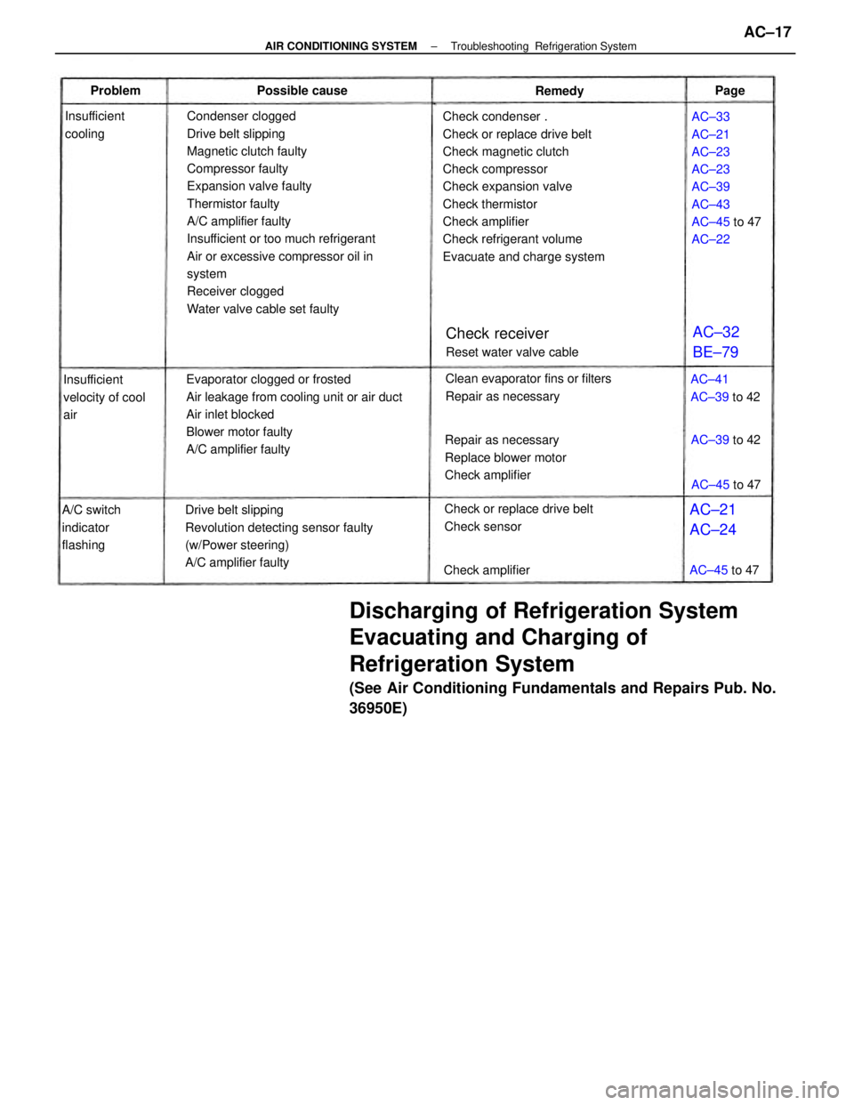
Discharging of Refrigeration System
Evacuating and Charging of
Refrigeration System
(See Air Conditioning Fundamentals and Repairs Pub. No.
36950E)
Condenser clogged
Drive belt slipping
Magnetic clutch faulty
Compressor faulty
Expansion valve faulty
Thermistor faulty
A/C amplifier faulty
Insufficient or too much refrigerant
Air or excessive compressor oil in
system
Receiver clogged
Water valve cable set faultyCheck condenser .
Check or replace drive belt
Check magnetic clutch
Check compressor
Check expansion valve
Check thermistor
Check amplifier
Check refrigerant volume
Evacuate and charge system
Evaporator clogged or frosted
Air leakage from cooling unit or air duct
Air inlet blocked
Blower motor faulty
A/C amplifier faulty
Drive belt slipping
Revolution detecting sensor faulty
(w/Power steering)
A/C amplifier faultyAC±33
AC±21
AC±23
AC±23
AC±39
AC±43
AC±45 to 47
AC±22
Repair as necessary
Replace blower motor
Check amplifierClean evaporator fins or filters
Repair as necessary
Check or replace drive belt
Check sensor
Check receiver
Reset water valve cable
A/C switch
indicator
flashingInsufficient
velocity of cool
airAC±41
AC±39 to 42 Insufficient
cooling
Check amplifier Possible cause
AC±21
AC±24AC±32
BE±79
AC±39 to 42
AC±45 to 47
AC±45 to 47 Remedy ProblemPage
± AIR CONDITIONING SYSTEMTroubleshooting Refrigeration SystemAC±17
Page 218 of 2389
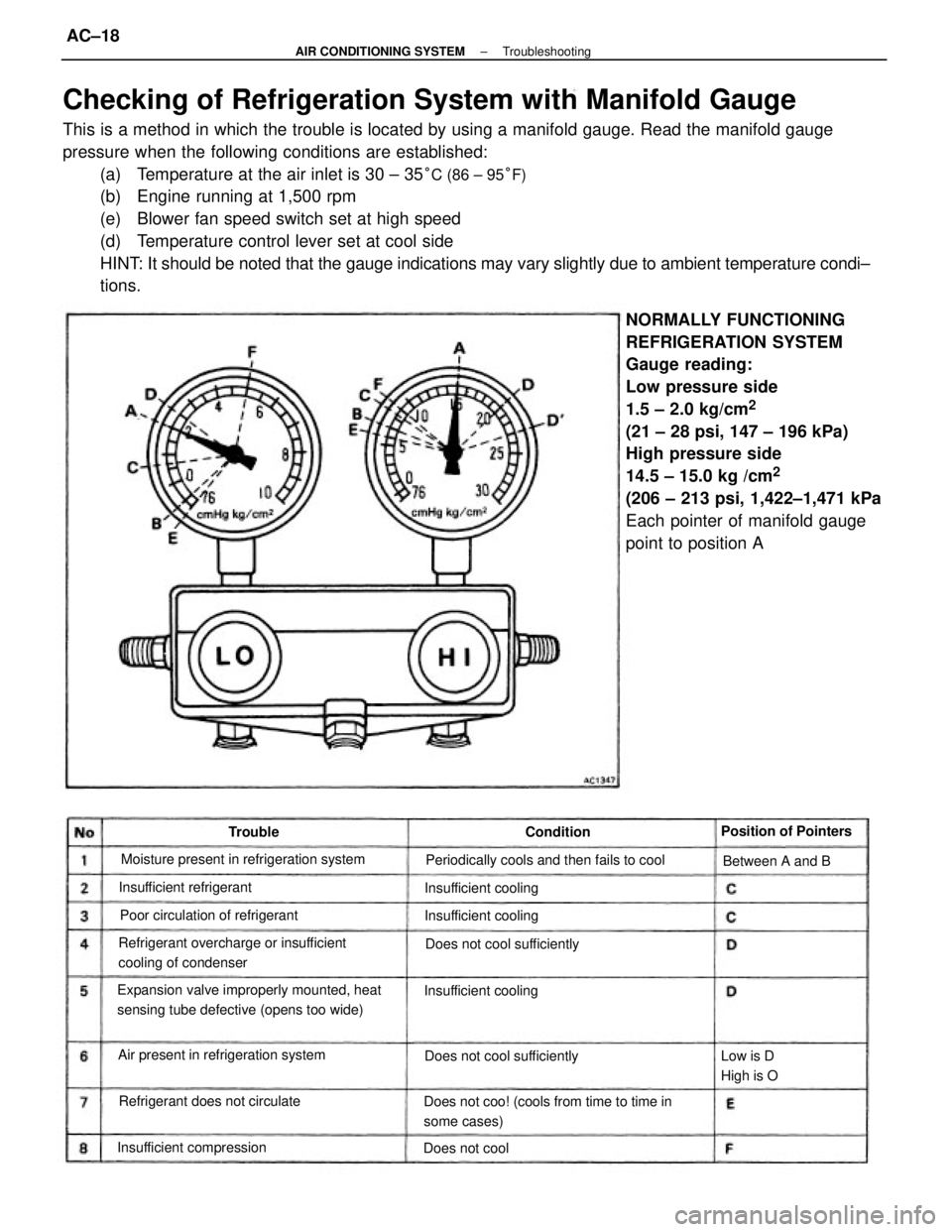
Checking of Refrigeration System with Manifold Gauge
This is a method in which the trouble is located by using a manifold gauge. Read the manifold gauge
pressure when the following conditions are established:
(a) Temperature at the air inlet is 30 ± 35
°C (86 ± 95°F)
(b) Engine running at 1,500 rpm
(e) Blower fan speed switch set at high speed
(d) Temperature control lever set at cool side
HINT: It should be noted that the gauge indications may vary slightly due to ambient temperature condi±
tions.
NORMALLY FUNCTIONING
REFRIGERATION SYSTEM
Gauge reading:
Low pressure side
1.5 ± 2.0 kg/cm
2
(21 ± 28 psi, 147 ± 196 kPa)
High pressure side
14.5 ± 15.0 kg /cm
2
(206 ± 213 psi, 1,422±1,471 kPa
Each pointer of manifold gauge
point to position A
Expansion valve improperly mounted, heat
sensing tube defective (opens too wide)
Does not coo! (cools from time to time in
some cases) Refrigerant overcharge or insufficient
cooling of condenserMoisture present in refrigeration system
Periodically cools and then fails to cool
Air present in refrigeration systemPoor circulation of refrigerant
Refrigerant does not circulateDoes not cool sufficiently
Does not cool sufficiently
Insufficient compressionInsufficient refrigerantPosition of Pointers
Insufficient cooling Insufficient cooling
Insufficient cooling
Low is D
High is OBetween A and B
Does not coolCondition Trouble
± AIR CONDITIONING SYSTEMTroubleshootingAC±18
Page 219 of 2389
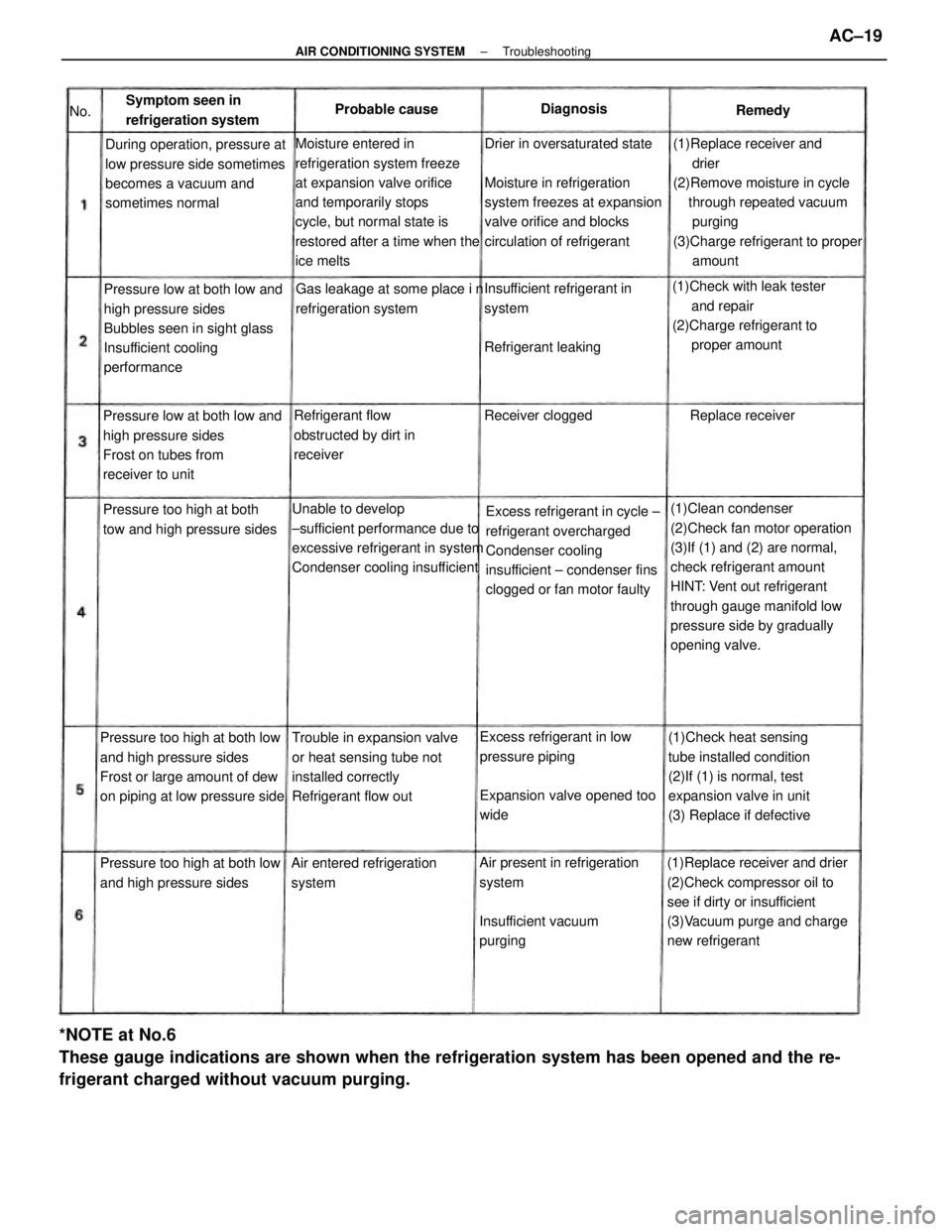
*NOTE at No.6
These gauge indications are shown when the refrigeration system has been opened and the re-
frigerant charged without vacuum purging.
(1)Clean condenser
(2)Check fan motor operation
(3)If (1) and (2) are normal,
check refrigerant amount
HINT: Vent out refrigerant
through gauge manifold low
pressure side by gradually
opening valve.
(1)Replace receiver and drier
(2)Check compressor oil to
see if dirty or insufficient
(3)Vacuum purge and charge
new refrigerant Drier in oversaturated state
Moisture in refrigeration
system freezes at expansion
valve orifice and blocks
circulation of refrigerant(1)Replace receiver and
drier
(2)Remove moisture in cycle
through repeated vacuum
purging
(3)Charge refrigerant to proper
amount
Excess refrigerant in cycle ±
refrigerant overcharged
Condenser cooling
insufficient ± condenser fins
clogged or fan motor faulty Unable to develop
±sufficient performance due to
excessive refrigerant in system
Condenser cooling insufficientMoisture entered in
refrigeration system freeze
at expansion valve orifice
and temporarily stops
cycle, but normal state is
restored after a time when the
ice melts
Pressure too high at both low
and high pressure sides
Frost or large amount of dew
on piping at low pressure side(1)Check heat sensing
tube installed condition
(2)If (1) is normal, test
expansion valve in unit
(3) Replace if defective Pressure low at both low and
high pressure sides
Bubbles seen in sight glass
Insufficient cooling
performance
Air present in refrigeration
system
Insufficient vacuum
purging During operation, pressure at
low pressure side sometimes
becomes a vacuum and
sometimes normal
Trouble in expansion valve
or heat sensing tube not
installed correctly
Refrigerant flow out Pressure low at both low and
high pressure sides
Frost on tubes from
receiver to unit(1)Check with leak tester
and repair
(2)Charge refrigerant to
proper amount
Excess refrigerant in low
pressure piping
Expansion valve opened too
wideInsufficient refrigerant in
system
Refrigerant leaking
Pressure too high at both low
and high pressure sidesPressure too high at both
tow and high pressure sidesGas leakage at some place i n
refrigeration system
Refrigerant flow
obstructed by dirt in
receiver
Air entered refrigeration
system Symptom seen in
refrigeration system
Receiver clogged Replace receiver Probable causeDiagnosis
Remedy
No.
± AIR CONDITIONING SYSTEMTroubleshootingAC±19
Page 220 of 2389
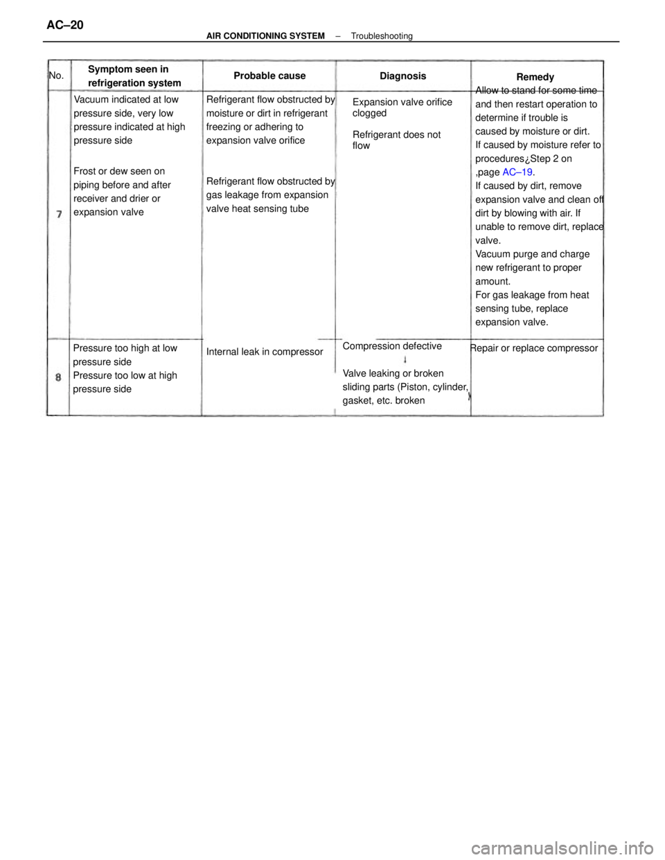
Allow to stand for some time
and then restart operation to
determine if trouble is
caused by moisture or dirt.
If caused by moisture refer to
procedures¿Step 2 on
,page AC±19.
If caused by dirt, remove
expansion valve and clean off
dirt by blowing with air. If
unable to remove dirt, replace
valve.
Vacuum purge and charge
new refrigerant to proper
amount.
For gas leakage from heat
sensing tube, replace
expansion valve. Refrigerant flow obstructed by
moisture or dirt in refrigerant
freezing or adhering to
expansion valve orifice
Refrigerant flow obstructed by
gas leakage from expansion
valve heat sensing tube
Internal leak in compressor Vacuum indicated at low
pressure side, very low
pressure indicated at high
pressure side
Pressure too high at low
pressure side
Pressure too low at high
pressure sideFrost or dew seen on
piping before and after
receiver and drier or
expansion valve
Repair or replace compressor Symptom seen in
refrigeration systemProbable cause
Diagnosis
Remedy No.
Expansion valve orifice
clogged
Refrigerant does not
flow
Compression defective
Valve leaking or broken
sliding parts (Piston, cylinder,
gasket, etc. broken
± AIR CONDITIONING SYSTEMTroubleshootingAC±20