TOYOTA CAMRY V20 1986 Service Information
CAMRY V20 1986
TOYOTA
TOYOTA
https://www.carmanualsonline.info/img/14/57449/w960_57449-0.png
TOYOTA CAMRY V20 1986 Service Information
Trending: fuel consumption, tires, ECU, jack points, check oil, washer fluid, airbag
Page 251 of 2389
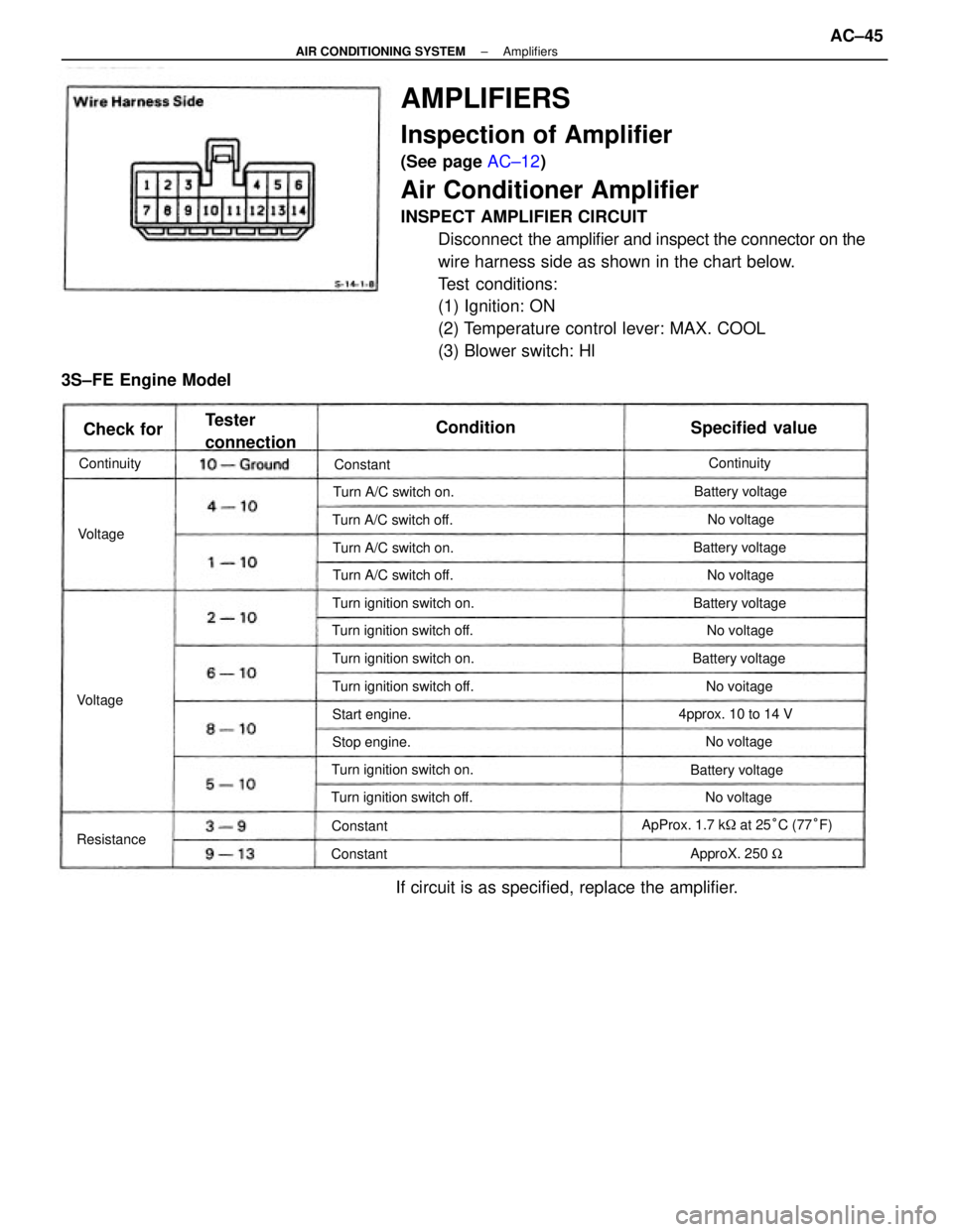
AMPLIFIERS
Inspection of Amplifier
(See page AC±12)
Air Conditioner Amplifier
INSPECT AMPLIFIER CIRCUIT
Disconnect the amplifier and inspect the connector on the
wire harness side as shown in the chart below.
Test conditions:
(1) Ignition: ON
(2) Temperature control lever: MAX. COOL
(3) Blower switch: Hl
If circuit is as specified, replace the amplifier.
ApProx. 1.7 k� at 25°C (77°F)
3S±FE Engine Model
Turn ignition switch off.Turn ignition switch on.
Turn ignition switch off.Turn ignition switch on.
Turn ignition switch off.
Turn ignition switch on.Turn A/C switch off.
Turn A/C switch on.
Turn A/C switch off.Turn A/C switch on.
4pprox. 10 to 14 V
Tester
connectionSpecified value
Battery voltage
Battery voltageBattery voltageBattery voltage
Battery voltage
ApproX. 250 W Start engine.
Stop engine.No voltageNo voltage
No voltage
No voitage
No voltageNo voltage ContinuityContinuity
Resistance
Condition
Check for
Constant
ConstantConstant
Voltage
Voltage
± AIR CONDITIONING SYSTEMAmplifiersAC±45
Page 252 of 2389
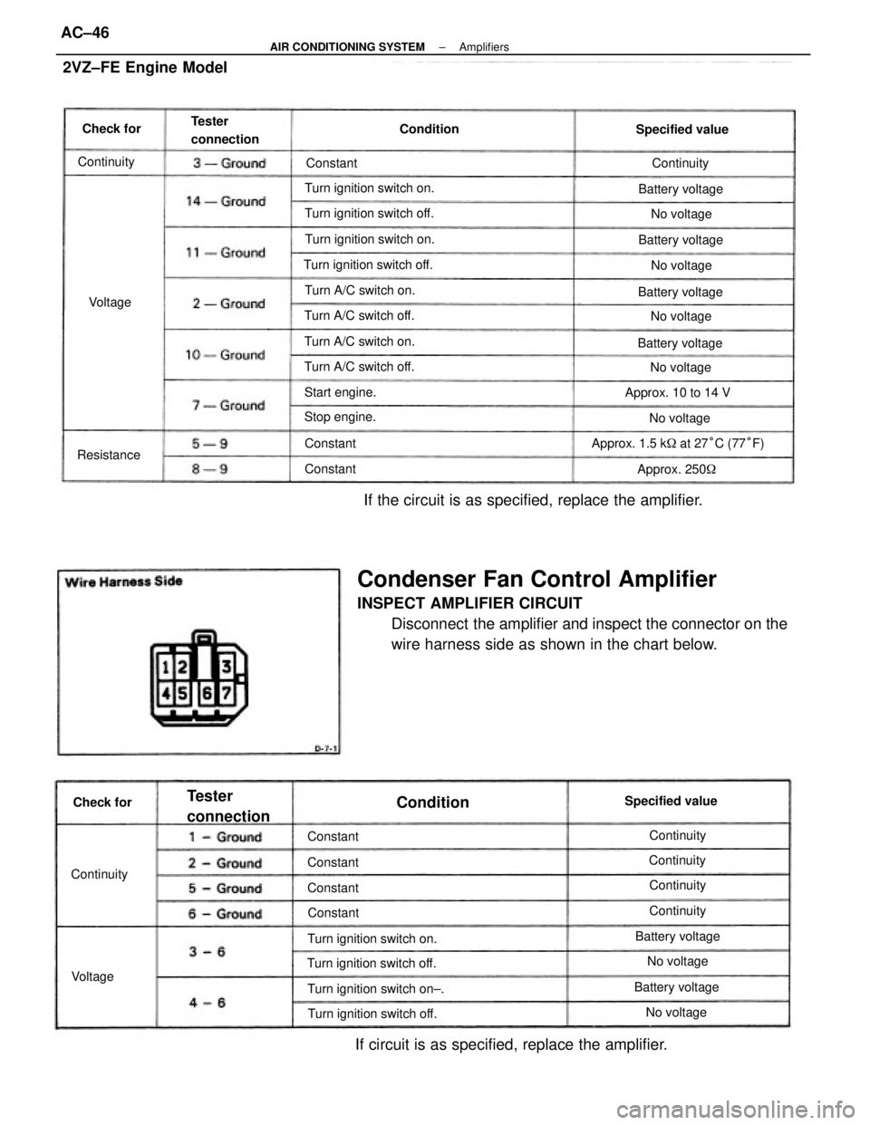
Condenser Fan Control Amplifier
INSPECT AMPLIFIER CIRCUIT
Disconnect the amplifier and inspect the connector on the
wire harness side as shown in the chart below. If the circuit is as specified, replace the amplifier.
If circuit is as specified, replace the amplifier. 2VZ±FE Engine Model
Approx. 1.5 k� at 27°C (77°F)
Turn ignition switch off.
Turn ignition switch off. Turn ignition switch on±. Turn ignition switch on. Turn ignition switch off.Turn ignition switch on. Turn ignition switch off. Turn ignition switch on.
Turn A/C switch on.
Turn A/C switch on.
Turn A/C switch off. Turn A/C switch off.
Tester
connection
Approx. 10 to 14 V Tester
connection
Specified valueSpecified value
Battery voltageBattery voltageBattery voltage Battery voltage
Battery voltage
Approx. 250� Battery voltage
Start engine.
Stop engine.
No voltageNo voltage
No voltage
No voltage
No voltage ContinuityNo voltageNo voltage
ContinuityContinuity
Continuity Continuity
Continuity
Condition
Continuity ResistanceCondition
Check forCheck for
Constant Constant Constant
Constant Constant
Constant Constant
VoltageVoltage
± AIR CONDITIONING SYSTEMAmplifiersAC±46
Page 253 of 2389
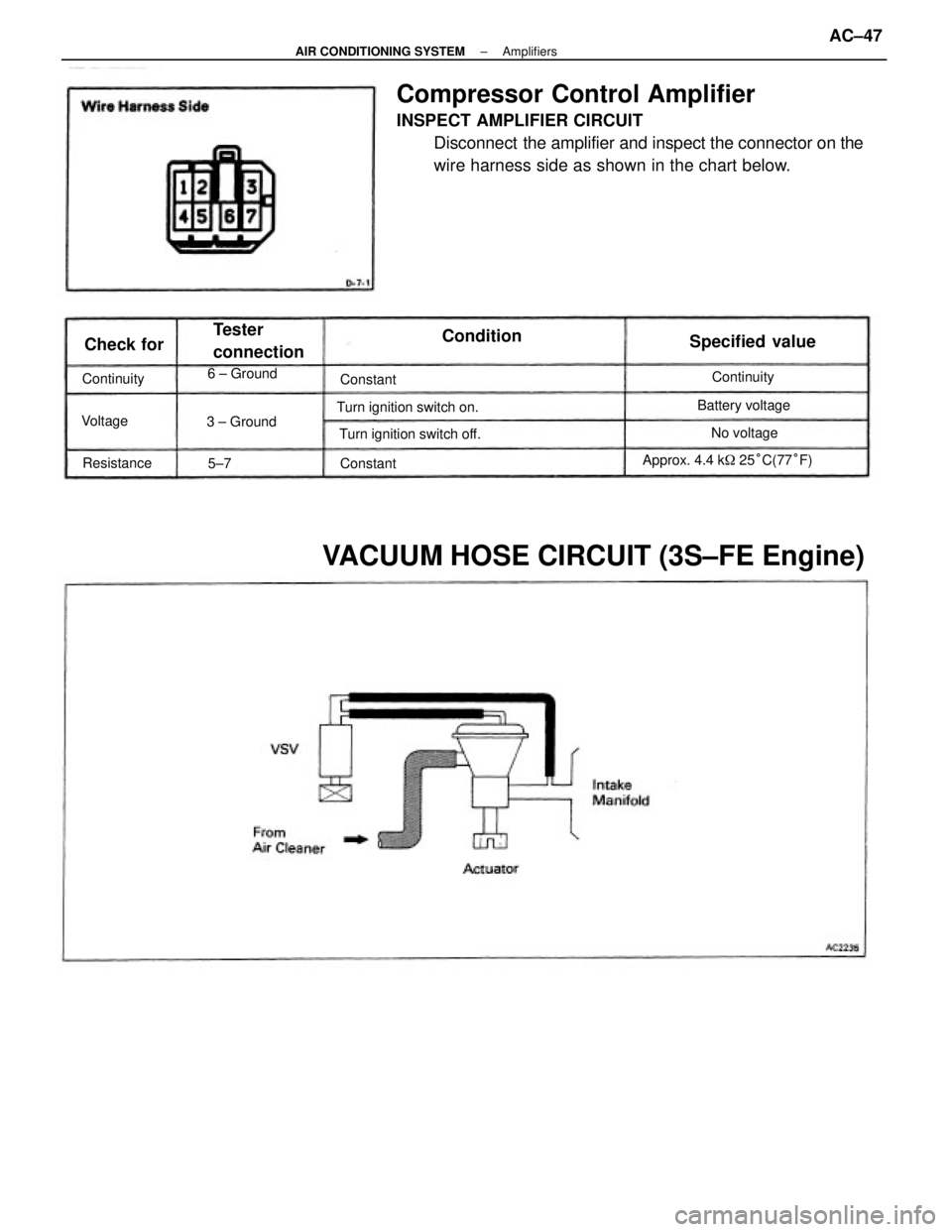
Compressor Control Amplifier
INSPECT AMPLIFIER CIRCUIT
Disconnect the amplifier and inspect the connector on the
wire harness side as shown in the chart below.
VACUUM HOSE CIRCUIT (3S±FE Engine)
Approx. 4.4 k� 25°C(77°F) Turn ignition switch on.
Turn ignition switch off.
Tester
connectionSpecified value
3 ± GroundBattery voltage 6 ± Ground
No voltage ContinuityContinuity
Resistance
Condition
Check for
Constant Constant
Voltage
5±7
± AIR CONDITIONING SYSTEMAmplifiersAC±47
Page 254 of 2389
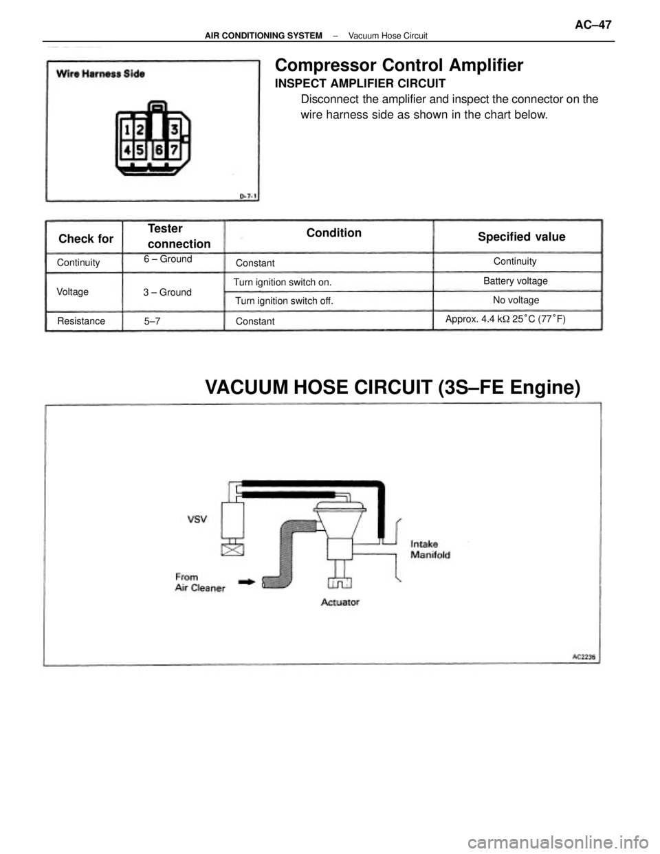
Compressor Control Amplifier
INSPECT AMPLIFIER CIRCUIT
Disconnect the amplifier and inspect the connector on the
wire harness side as shown in the chart below.
VACUUM HOSE CIRCUIT (3S±FE Engine)
Approx. 4.4 k� 25°C (77°F) Turn ignition switch on.
Turn ignition switch off.
Tester
connectionSpecified value
3 ± GroundBattery voltage 6 ± Ground
No voltage ContinuityContinuity
Resistance
Condition
Check for
Constant Constant
Voltage
5±7
± AIR CONDITIONING SYSTEMVacuum Hose CircuitAC±47
Page 255 of 2389
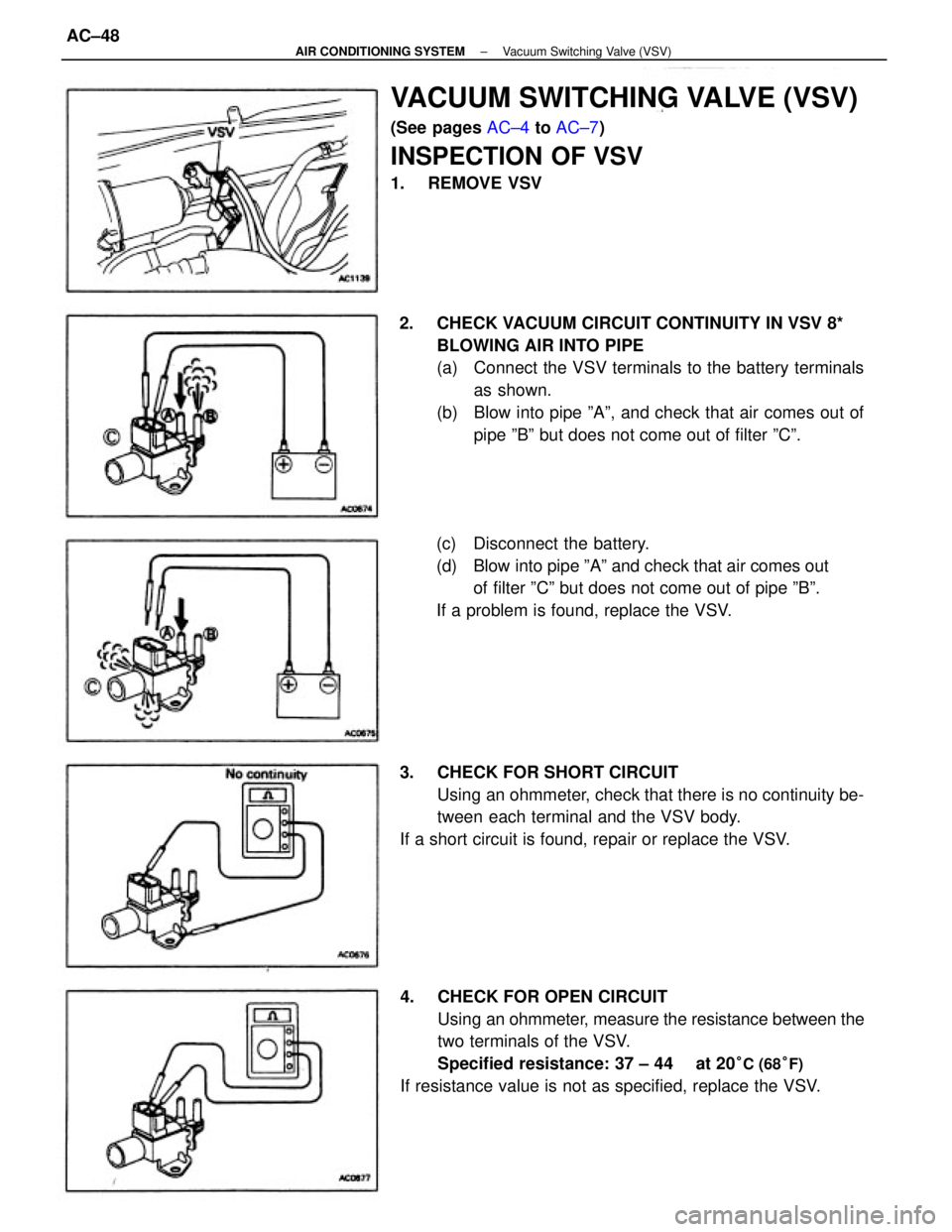
VACUUM SWITCHING VALVE (VSV)
(See pages AC±4 to AC±7)
INSPECTION OF VSV
1. REMOVE VSV
2. CHECK VACUUM CIRCUIT CONTINUITY IN VSV 8*
BLOWING AIR INTO PIPE
(a) Connect the VSV terminals to the battery terminals
as shown.
(b) Blow into pipe ºAº, and check that air comes out of
pipe ºBº but does not come out of filter ºCº.
4. CHECK FOR OPEN CIRCUIT
Using an ohmmeter, measure the resistance between the
two terminals of the VSV.
Specified resistance: 37 ± 44
� at 20°C (68°F)
If resistance value is not as specified, replace the VSV. 3. CHECK FOR SHORT CIRCUIT
Using an ohmmeter, check that there is no continuity be-
tween each terminal and the VSV body.
If a short circuit is found, repair or replace the VSV.(c) Disconnect the battery.
(d) Blow into pipe ºAº and check that air comes out
of filter ºCº but does not come out of pipe ºBº.
If a problem is found, replace the VSV.
± AIR CONDITIONING SYSTEMVacuum Switching Valve (VSV)AC±48
Page 256 of 2389
TROUBLESHOOTING
Basic Troubleshooting
Before troubleshooting an ECT, first determine whether the problem is electrical or mechanical.
To do this, just refer to the basic troubleshooting flow±chart provided below.
If the cause is already known, using the basic troubleshooting chart below along with the general
troubleshooting chart on the following pages should speed the procedure.
Stall Test, Time Lag Test and
Hydraulic Test Read Diagnostic Code
(See page AT±17)
Manual Shifting Test
(See page AT±23)
Electrical Control System CheckPreliminary Check
(See page AT±21 )Repair or
Replace
Repair or ReplaceRepair Transaxle Bad
BadBad
Bad
Bad
± AUTOMATIC TRANSAXLETroubleshooting (Basic Troubleshooting) (A140L and
A140E)AT±11
Page 257 of 2389
AUTOMATIC TRANSAXLE
AUTOMATIC TRANSAXLEAT±1
Page 258 of 2389
MEMO
AUTOMATIC TRANSAXLEAT±2
Page 259 of 2389
A140L AND A140E
AUTOMATIC TRANSAXLE
AUTOMATIC TRANSAXLEAT±3
Page 260 of 2389
DESCRIPTION
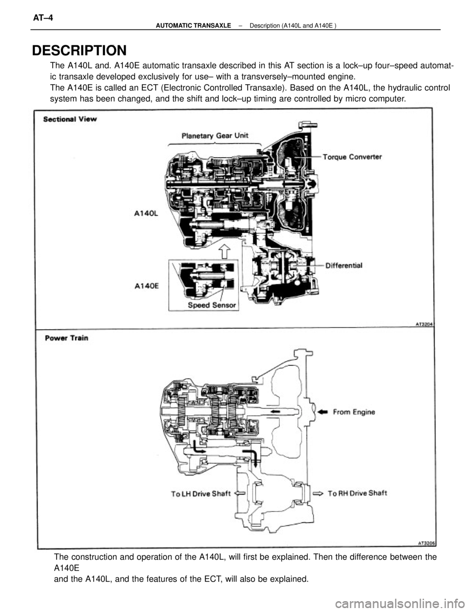
The A140L and. A140E automatic transaxle described in this AT section is a lock±up four±speed automat-
ic transaxle developed exclusively for use± with a transversely±mounted engine.
The A140E is called an ECT (Electronic Controlled Transaxle). Based on the A140L, the hydraulic control
system has been changed, and the shift and lock±up timing are controlled by micro computer.
The construction and operation of the A140L, will first be explained. Then the difference between the
A140E
and the A140L, and the features of the ECT, will also be explained.
± AUTOMATIC TRANSAXLEDescription (A140L and A140E )AT±4
Trending: battery replacement, wheel bolt torque, condition, set clock, ABS, airbag, battery location


