TOYOTA CAMRY V20 1986 Service Information
Manufacturer: TOYOTA, Model Year: 1986, Model line: CAMRY V20, Model: TOYOTA CAMRY V20 1986Pages: 2389, PDF Size: 84.44 MB
Page 2341 of 2389
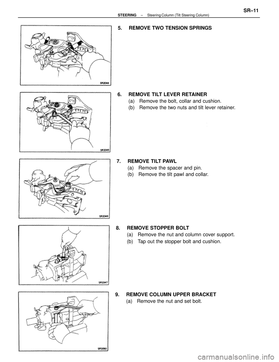
6. REMOVE TILT LEVER RETAINER
(a) Remove the bolt, collar and cushion.
(b) Remove the two nuts and tilt lever retainer.
8. REMOVE STOPPER BOLT
(a) Remove the nut and column cover support.
(b) Tap out the stopper bolt and cushion. 7. REMOVE TILT PAWL
(a) Remove the spacer and pin.
(b) Remove the tilt pawl and collar.
9. REMOVE COLUMN UPPER BRACKET
(a) Remove the nut and set bolt. 5. REMOVE TWO TENSION SPRINGS
± STEERINGSteering Column (Tilt Steering Column)SR±11
Page 2342 of 2389
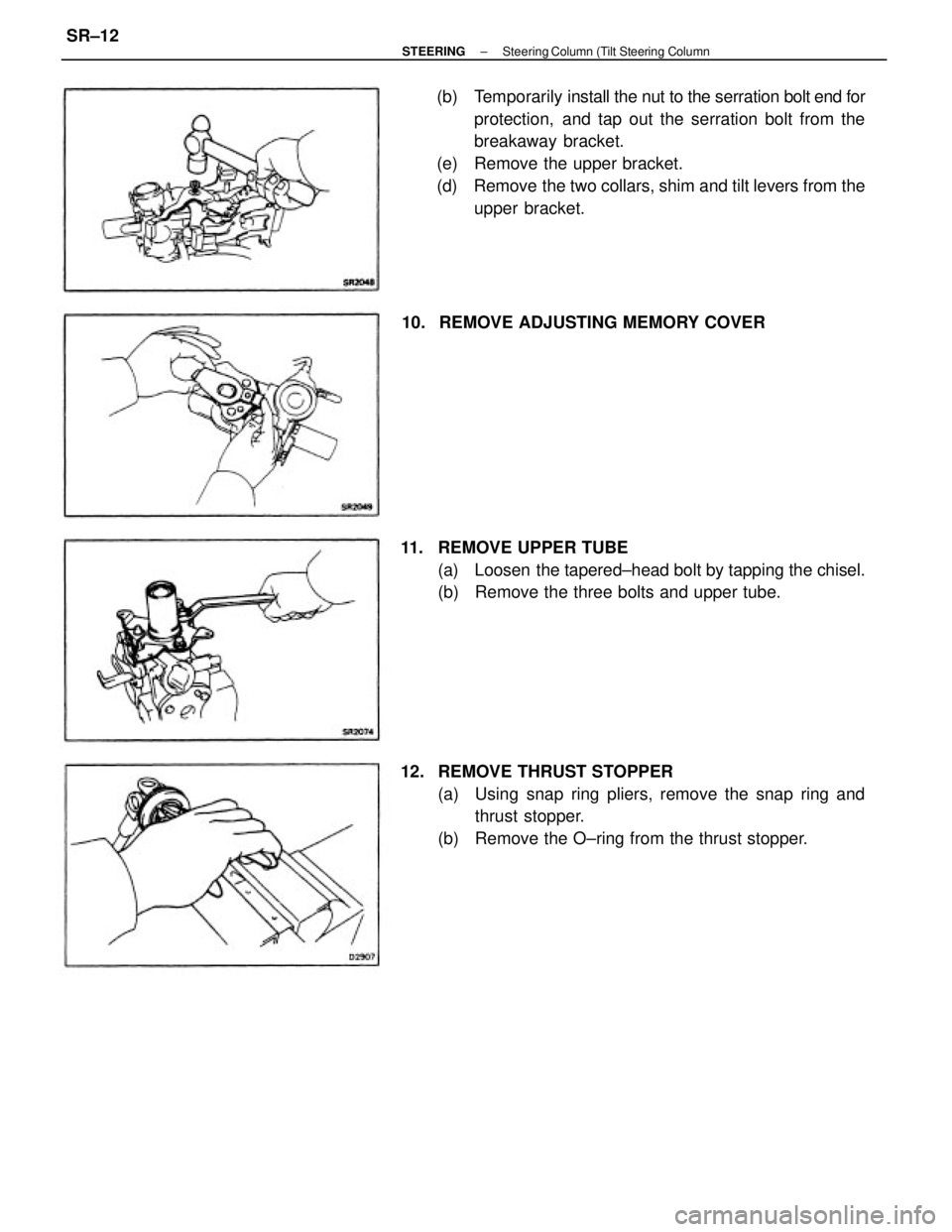
(b) Temporarily install the nut to the serration bolt end for
protection, and tap out the serration bolt from the
breakaway bracket.
(e) Remove the upper bracket.
(d) Remove the two collars, shim and tilt levers from the
upper bracket.
12. REMOVE THRUST STOPPER
(a) Using snap ring pliers, remove the snap ring and
thrust stopper.
(b) Remove the O±ring from the thrust stopper. 11. REMOVE UPPER TUBE
(a) Loosen the tapered±head bolt by tapping the chisel.
(b) Remove the three bolts and upper tube. 10. REMOVE ADJUSTING MEMORY COVER
± STEERINGSteering Column (Tilt Steering ColumnSR±12
Page 2343 of 2389
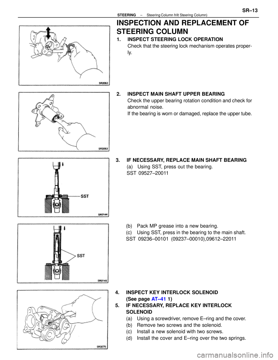
4. INSPECT KEY INTERLOCK SOLENOID
(See page AT±41 1)
5. IF NECESSARY, REPLACE KEY INTERLOCK
SOLENOID
(a) Using a screwdriver, remove E±ring and the cover.
(b) Remove two screws and the solenoid.
(c) Install a new solenoid with two screws.
(d) Install the cover and E±ring over the two springs.
INSPECTION AND REPLACEMENT OF
STEERING COLUMN
1. INSPECT STEERING LOCK OPERATION
Check that the steering lock mechanism operates proper-
ly.
2. INSPECT MAIN SHAFT UPPER BEARING
Check the upper bearing rotation condition and check for
abnormal noise.
If the bearing is worn or damaged, replace the upper tube.
3. IF NECESSARY, REPLACE MAIN SHAFT BEARING
(a) Using SST, press out the bearing.
SST 09527±20011
(b) Pack MP grease into a new bearing.
(c) Using SST, press in the bearing to the main shaft.
SST 09236±00101 (09237±00010),09612±22011
± STEERINGSteering Column frilt Steering Column)SR±13
Page 2344 of 2389
ASSEMBLY OF STEERING COLUMN
(See page SR±9)
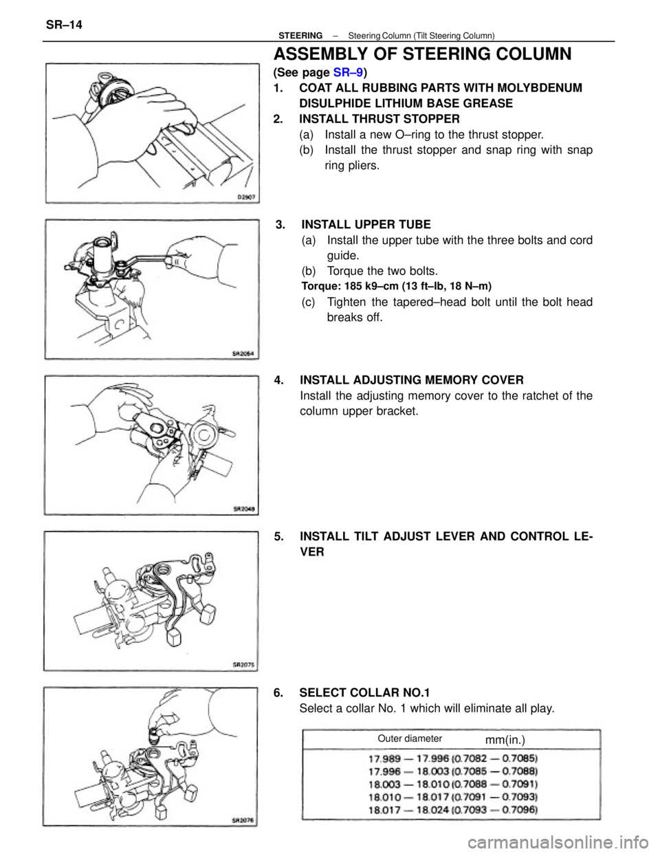
1. COAT ALL RUBBING PARTS WITH MOLYBDENUM
DISULPHIDE LITHIUM BASE GREASE
2. INSTALL THRUST STOPPER
(a) Install a new O±ring to the thrust stopper.
(b) Install the thrust stopper and snap ring with snap
ring pliers.
3. INSTALL UPPER TUBE
(a) Install the upper tube with the three bolts and cord
guide.
(b) Torque the two bolts.
Torque: 185 k9±cm (13 ft±Ib, 18 N±m)
(c) Tighten the tapered±head bolt until the bolt head
breaks off.
4. INSTALL ADJUSTING MEMORY COVER
Install the adjusting memory cover to the ratchet of the
column upper bracket.
6. SELECT COLLAR NO.1
Select a collar No. 1 which will eliminate all play. 5. INSTALL TILT ADJUST LEVER AND CONTROL LE-
VER
Outer diametermm(in.)
± STEERINGSteering Column (Tilt Steering Column)SR±14
Page 2345 of 2389
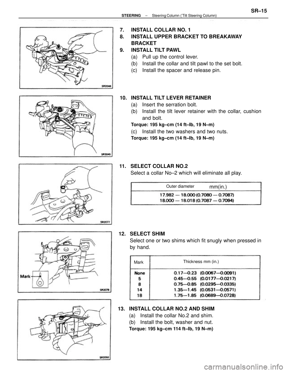
10. INSTALL TILT LEVER RETAINER
(a) Insert the serration bolt.
(b) Install the tilt lever retainer with the collar, cushion
and bolt.
Torque: 195 kg±cm (14 ft±Ib, 19 N±m)
(c) Install the two washers and two nuts.
Torque: 195 kg±cm (14 ft±Ib, 19 N±m)
7. INSTALL COLLAR NO. 1
8. INSTALL UPPER BRACKET TO BREAKAWAY
BRACKET
9. INSTALL TILT PAWL
(a) Pull up the control lever.
(b) Install the collar and tilt pawl to the set bolt.
(c) Install the spacer and release pin.
13. INSTALL COLLAR NO.2 AND SHIM
(a) Install the collar No.2 and shim.
(b) Install the bolt, washer and nut.
Torque: 195 kg±cm 114 ft±Ib, 19 N±m)
12. SELECT SHIM
Select one or two shims which fit snugly when pressed in
by hand. 11. SELECT COLLAR NO.2
Select a collar No±2 which will eliminate all play.
Thickness mm (in.) Outer diameter
mm(in.)
Mark
± STEERINGSteering Column ('Tilt Steering Column)SR±15
Page 2346 of 2389
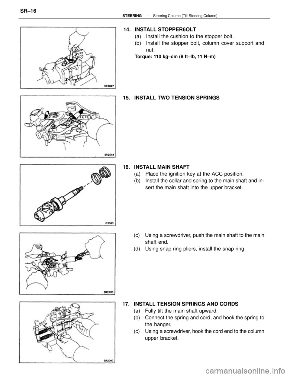
17. INSTALL TENSION SPRINGS AND CORDS
(a) Fully tilt the main shaft upward.
(b) Connect the spring and cord, and hook the spring to
the hanger.
(c) Using a screwdriver, hook the cord end to the column
upper bracket. 14. INSTALL STOPPER6OLT
(a) Install the cushion to the stopper bolt.
(b) Install the stopper bolt, column cover support and
nut.
Torque: 110 kg±cm (8 ft±lb, 11 N±m)
16. INSTALL MAIN SHAFT
(a) Place the ignition key at the ACC position.
(b) Install the collar and spring to the main shaft and in-
sert the main shaft into the upper bracket.
(c) Using a screwdriver, push the main shaft to the main
shaft end.
(d) Using snap ring pliers, install the snap ring. 15. INSTALL TWO TENSION SPRINGS
± STEERINGSteering Column (Tilt Steering Column)SR±16
Page 2347 of 2389
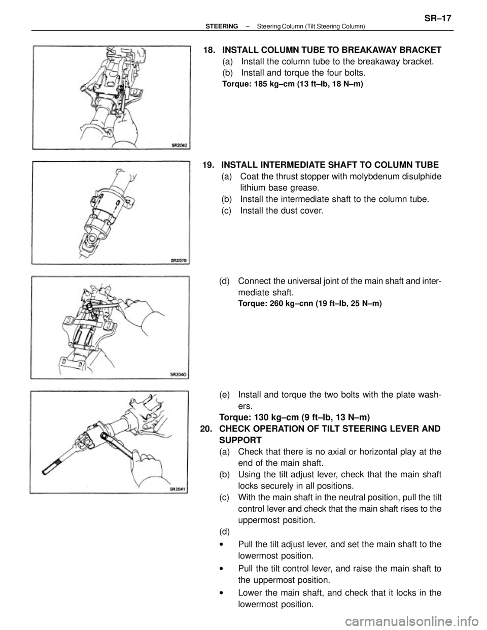
(e) Install and torque the two bolts with the plate wash-
ers.
Torque: 130 kg±cm (9 ft±Ib, 13 N±m)
20. CHECK OPERATION OF TILT STEERING LEVER AND
SUPPORT
(a) Check that there is no axial or horizontal play at the
end of the main shaft.
(b) Using the tilt adjust lever, check that the main shaft
locks securely in all positions.
(c) With the main shaft in the neutral position, pull the tilt
control lever and check that the main shaft rises to the
uppermost position.
(d)
wPull the tilt adjust lever, and set the main shaft to the
lowermost position.
wPull the tilt control lever, and raise the main shaft to
the uppermost position.
wLower the main shaft, and check that it locks in the
lowermost position. 19. INSTALL INTERMEDIATE SHAFT TO COLUMN TUBE
(a) Coat the thrust stopper with molybdenum disulphide
lithium base grease.
(b) Install the intermediate shaft to the column tube.
(c) Install the dust cover. 18. INSTALL COLUMN TUBE TO BREAKAWAY BRACKET
(a) Install the column tube to the breakaway bracket.
(b) Install and torque the four bolts.
Torque: 185 kg±cm (13 ft±Ib, 18 N±m)
(d) Connect the universal joint of the main shaft and inter-
mediate shaft.
Torque: 260 kg±cnn (19 ft±Ib, 25 N±m)
± STEERINGSteering Column (Tilt Steering Column)SR±17
Page 2348 of 2389
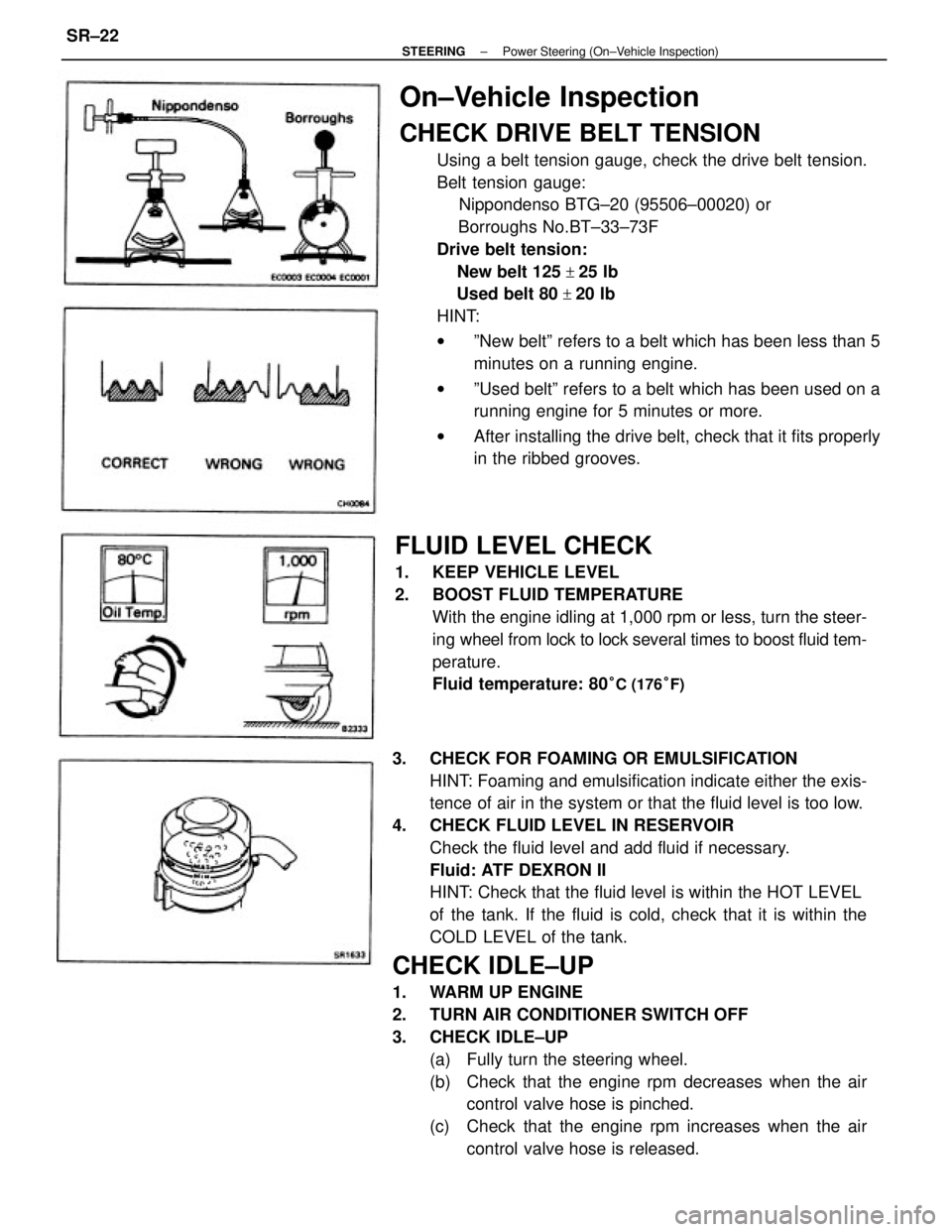
3. CHECK FOR FOAMING OR EMULSIFICATION
HINT: Foaming and emulsification indicate either the exis-
tence of air in the system or that the fluid level is too low.
4. CHECK FLUID LEVEL IN RESERVOIR
Check the fluid level and add fluid if necessary.
Fluid: ATF DEXRON II
HINT: Check that the fluid level is within the HOT LEVEL
of the tank. If the fluid is cold, check that it is within the
COLD LEVEL of the tank.
CHECK IDLE±UP
1. WARM UP ENGINE
2. TURN AIR CONDITIONER SWITCH OFF
3. CHECK IDLE±UP
(a) Fully turn the steering wheel.
(b) Check that the engine rpm decreases when the air
control valve hose is pinched.
(c) Check that the engine rpm increases when the air
control valve hose is released.
On±Vehicle Inspection
CHECK DRIVE BELT TENSION
Using a belt tension gauge, check the drive belt tension.
Belt tension gauge:
Nippondenso BTG±20 (95506±00020) or
Borroughs No.BT±33±73F
Drive belt tension:
New belt 125
+25 Ib
Used belt 80
+20 Ib
HINT:
wºNew beltº refers to a belt which has been less than 5
minutes on a running engine.
wºUsed beltº refers to a belt which has been used on a
running engine for 5 minutes or more.
wAfter installing the drive belt, check that it fits properly
in the ribbed grooves.
FLUID LEVEL CHECK
1. KEEP VEHICLE LEVEL
2. BOOST FLUID TEMPERATURE
With the engine idling at 1,000 rpm or less, turn the steer-
ing wheel from lock to lock several times to boost fluid tem-
perature.
Fluid temperature: 80
°C (176°F)
± STEERINGPower Steering (On±Vehicle Inspection)SR±22
Page 2349 of 2389
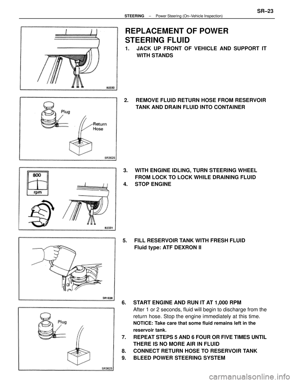
6. START ENGINE AND RUN IT AT 1,000 RPM
After 1 or 2 seconds, fluid will begin to discharge from the
return hose. Stop the engine immediately at this time.
NOTICE: Take care that some fluid remains left in the
reservoir tank.
7. REPEAT STEPS 5 AND 6 FOUR OR FIVE TIMES UNTIL
THERE IS NO MORE AIR IN FLUID
8. CONNECT RETURN HOSE TO RESERVOIR TANK
9. BLEED POWER STEERING SYSTEM
REPLACEMENT OF POWER
STEERING FLUID
1. JACK UP FRONT OF VEHICLE AND SUPPORT IT
WITH STANDS
3. WITH ENGINE IDLING, TURN STEERING WHEEL
FROM LOCK TO LOCK WHILE DRAINING FLUID
4. STOP ENGINE2. REMOVE FLUID RETURN HOSE FROM RESERVOIR
TANK AND DRAIN FLUID INTO CONTAINER
5. FILL RESERVOIR TANK WITH FRESH FLUID
Fluid type: ATF DEXRON II
± STEERINGPower Steering (On±Vehicle Inspection)SR±23
Page 2350 of 2389
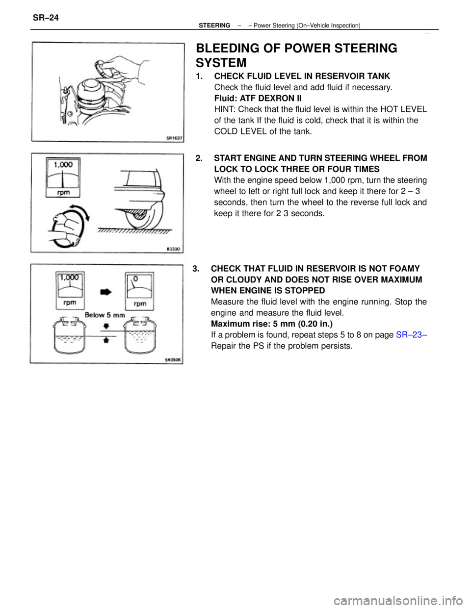
3. CHECK THAT FLUID IN RESERVOIR IS NOT FOAMY
OR CLOUDY AND DOES NOT RISE OVER MAXIMUM
WHEN ENGINE IS STOPPED
Measure the fluid level with the engine running. Stop the
engine and measure the fluid level.
Maximum rise: 5 mm (0.20 in.)
If a problem is found, repeat steps 5 to 8 on page SR±23±
Repair the PS if the problem persists.
BLEEDING OF POWER STEERING
SYSTEM
1. CHECK FLUID LEVEL IN RESERVOIR TANK
Check the fluid level and add fluid if necessary.
Fluid: ATF DEXRON II
HINT: Check that the fluid level is within the HOT LEVEL
of the tank If the fluid is cold, check that it is within the
COLD LEVEL of the tank.
2. START ENGINE AND TURN STEERING WHEEL FROM
LOCK TO LOCK THREE OR FOUR TIMES
With the engine speed below 1,000 rpm, turn the steering
wheel to left or right full lock and keep it there for 2 ± 3
seconds, then turn the wheel to the reverse full lock and
keep it there for 2 3 seconds.
± STEERING± Power Steering (On±Vehicle Inspection)SR±24