TOYOTA CAMRY V20 1986 Service Information
CAMRY V20 1986
TOYOTA
TOYOTA
https://www.carmanualsonline.info/img/14/57449/w960_57449-0.png
TOYOTA CAMRY V20 1986 Service Information
Trending: trailer, fog light, steering, body electrical, horn, battery capacity, set clock
Page 2361 of 2389
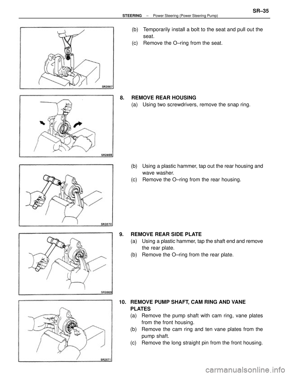
10. REMOVE PUMP SHAFT, CAM RING AND VANE
PLATES
(a) Remove the pump shaft with cam ring, vane plates
from the front housing.
(b) Remove the cam ring and ten vane plates from the
pump shaft.
(c) Remove the long straight pin from the front housing. 9. REMOVE REAR SIDE PLATE
(a) Using a plastic hammer, tap the shaft end and remove
the rear plate.
(b) Remove the O±ring from the rear plate.(b) Temporarily install a bolt to the seat and pull out the
seat.
(c) Remove the O±ring from the seat.
(b) Using a plastic hammer, tap out the rear housing and
wave washer.
(c) Remove the O±ring from the rear housing. 8. REMOVE REAR HOUSING
(a) Using two screwdrivers, remove the snap ring.
± STEERINGPower Steering (Power Steering Pump)SR±35
Page 2362 of 2389
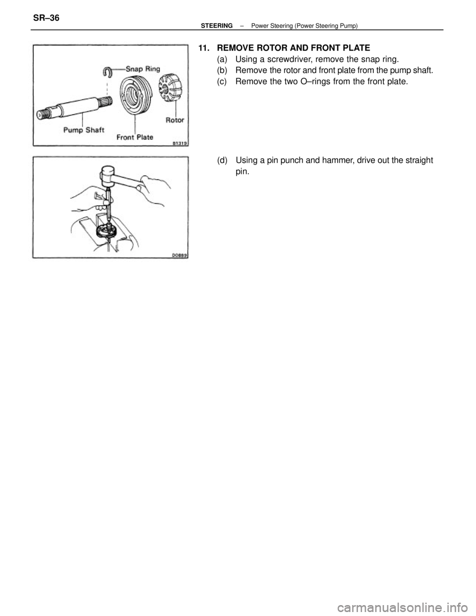
11. REMOVE ROTOR AND FRONT PLATE
(a) Using a screwdriver, remove the snap ring.
(b) Remove the rotor and front plate from the pump shaft.
(c) Remove the two O±rings from the front plate.
(d) Using a pin punch and hammer, drive out the straight
pin.
± STEERINGPower Steering (Power Steering Pump)SR±36
Page 2363 of 2389
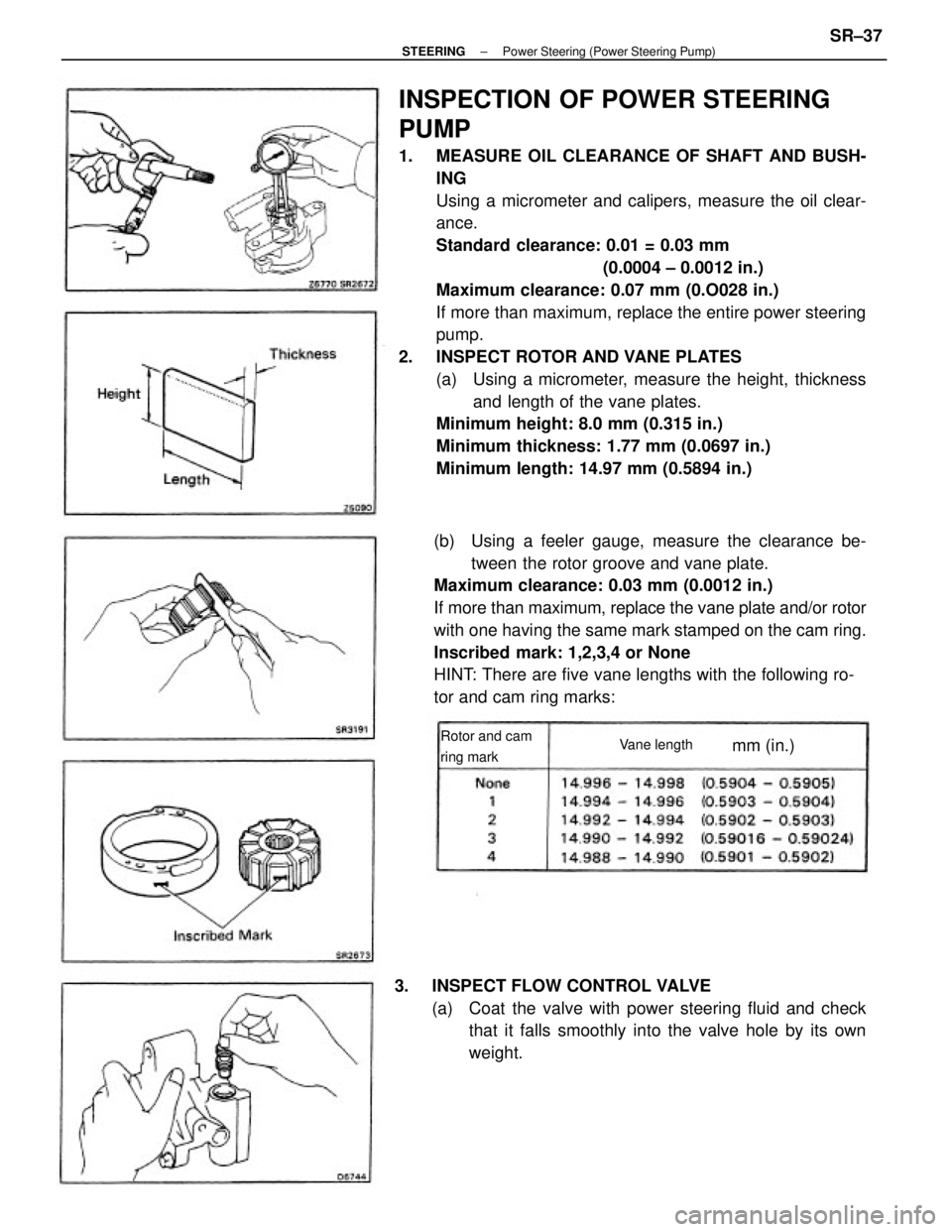
INSPECTION OF POWER STEERING
PUMP
1. MEASURE OIL CLEARANCE OF SHAFT AND BUSH-
ING
Using a micrometer and calipers, measure the oil clear-
ance.
Standard clearance: 0.01 = 0.03 mm
(0.0004 ± 0.0012 in.)
Maximum clearance: 0.07 mm (0.O028 in.)
If more than maximum, replace the entire power steering
pump.
2. INSPECT ROTOR AND VANE PLATES
(a) Using a micrometer, measure the height, thickness
and length of the vane plates.
Minimum height: 8.0 mm (0.315 in.)
Minimum thickness: 1.77 mm (0.0697 in.)
Minimum length: 14.97 mm (0.5894 in.)
(b) Using a feeler gauge, measure the clearance be-
tween the rotor groove and vane plate.
Maximum clearance: 0.03 mm (0.0012 in.)
If more than maximum, replace the vane plate and/or rotor
with one having the same mark stamped on the cam ring.
Inscribed mark: 1,2,3,4 or None
HINT: There are five vane lengths with the following ro-
tor and cam ring marks:
3. INSPECT FLOW CONTROL VALVE
(a) Coat the valve with power steering fluid and check
that it falls smoothly into the valve hole by its own
weight.
Rotor and cam
ring markVane lengthmm (in.)
± STEERINGPower Steering (Power Steering Pump)SR±37
Page 2364 of 2389
(b) Check the flow control valve for leakage.
Close.one of the holes and apply compressed air [4
±5 kg/crn
2 (57 ± 71 psi, 392 ± 490 kPa)] into the oppo-
site side, and confirm that air does not come out from
the end hole.
4. INSPECT FLOW CONTROL SPRING
Using a scale, measure the free length of the spring.
Spring length: 36 ± 38 mm (1.42 ± 1.49 in.)
If not within specification, replace the spring. If necessary, replace the valve with one having the
same letter as inscribed on the front housing.
Inscribed mark: A,6,C,6, E or F
5. IF NECESSARY, REPLACE OIL SEAL
A
(a) Using a screwdriver, pry out the oil seal.
(b) Using a socket wrench and hammer, drive in a new
oil seal.
± STEERINGPower Steering (Power Steering PumpSR±38
Page 2365 of 2389
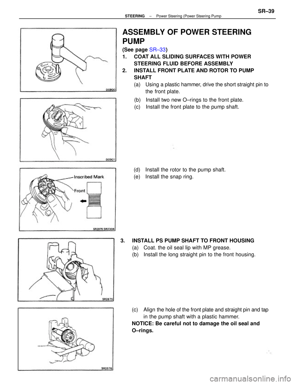
ASSEMBLY OF POWER STEERING
PUMP
(See page SR±33)
1. COAT ALL SLIDING SURFACES WITH POWER
STEERING FLUID BEFORE ASSEMBLY
2. INSTALL FRONT PLATE AND ROTOR TO PUMP
SHAFT
(a) Using a plastic hammer, drive the short straight pin to
the front plate.
(c) Align the hole of the front plate and straight pin and tap
in the pump shaft with a plastic hammer.
NOTICE: Be careful not to damage the oil seal and
O±rings. 3. INSTALL PS PUMP SHAFT TO FRONT HOUSING
(a) Coat. the oil seal lip with MP grease.
(b) Install the long straight pin to the front housing.(b) Install two new O±rings to the front plate.
(c) Install the front plate to the pump shaft.
(d) Install the rotor to the pump shaft.
(e) Install the snap ring.
± STEERINGPower Steering (Power Steering PumpSR±39
Page 2366 of 2389
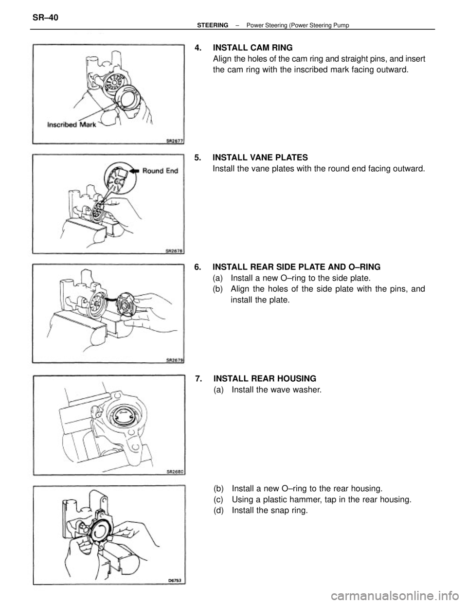
6. INSTALL REAR SIDE PLATE AND O±RING
(a) Install a new O±ring to the side plate.
(b) Align the holes of the side plate with the pins, and
install the plate.
(b) Install a new O±ring to the rear housing.
(c) Using a plastic hammer, tap in the rear housing.
(d) Install the snap ring. 4. INSTALL CAM RING
Align the holes of the cam ring and straight pins, and insert
the cam ring with the inscribed mark facing outward.
5. INSTALL VANE PLATES
Install the vane plates with the round end facing outward.
7. INSTALL REAR HOUSING
(a) Install the wave washer.
± STEERINGPower Steering (Power Steering PumpSR±40
Page 2367 of 2389
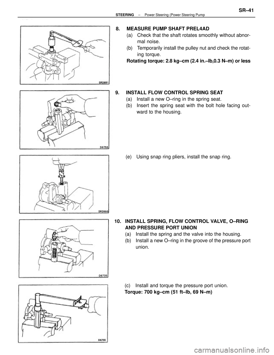
8. MEASURE PUMP SHAFT PREL4AD
(a) Check that the shaft rotates smoothly without abnor-
mal noise.
(b) Temporarily install the pulley nut and check the rotat-
ing torque.
Rotating torque: 2.8 kg±cm (2.4 in.±Ib,0.3 N±m) or less
10. INSTALL SPRING, FLOW CONTROL VALVE, O±RING
AND PRESSURE PORT UNION
(a) Install the spring and the valve into the housing.
(b) Install a new O±ring in the groove of the pressure port
union. 9. INSTALL FLOW CONTROL SPRING SEAT
(a) Install a new O±ring in the spring seat.
(b) Insert the spring seat with the bolt hole facing out-
ward to the housing.
(c) Install and torque the pressure port union.
Torque: 700 kg±cm (51 ft±Ib, 69 N±m)(e) Using snap ring pliers, install the snap ring.
± STEERINGPower Steering (Power Steering PumpSR±41
Page 2368 of 2389
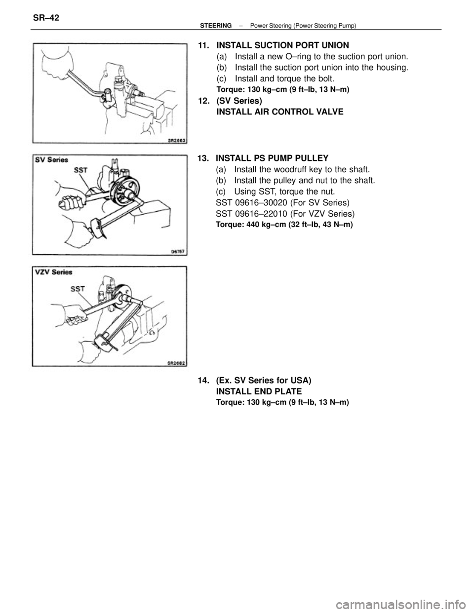
11. INSTALL SUCTION PORT UNION
(a) Install a new O±ring to the suction port union.
(b) Install the suction port union into the housing.
(c) Install and torque the bolt.
Torque: 130 kg±cm (9 ft±Ib, 13 N±m)
12. (SV Series)
INSTALL AIR CONTROL VALVE
13. INSTALL PS PUMP PULLEY
(a) Install the woodruff key to the shaft.
(b) Install the pulley and nut to the shaft.
(c) Using SST, torque the nut.
SST 09616±30020 (For SV Series)
SST 09616±22010 (For VZV Series)
Torque: 440 kg±cm (32 ft±Ib, 43 N±m)
14. (Ex. SV Series for USA)
INSTALL END PLATE
Torque: 130 kg±cm (9 ft±lb, 13 N±m)
± STEERINGPower Steering (Power Steering Pump)SR±42
Page 2369 of 2389
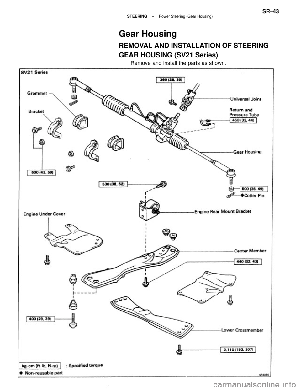
Gear Housing
REMOVAL AND INSTALLATION OF STEERING
GEAR HOUSING (SV21 Series)
Remove and install the parts as shown.
± STEERINGPower Steering (Gear Housing)SR±43
Page 2370 of 2389
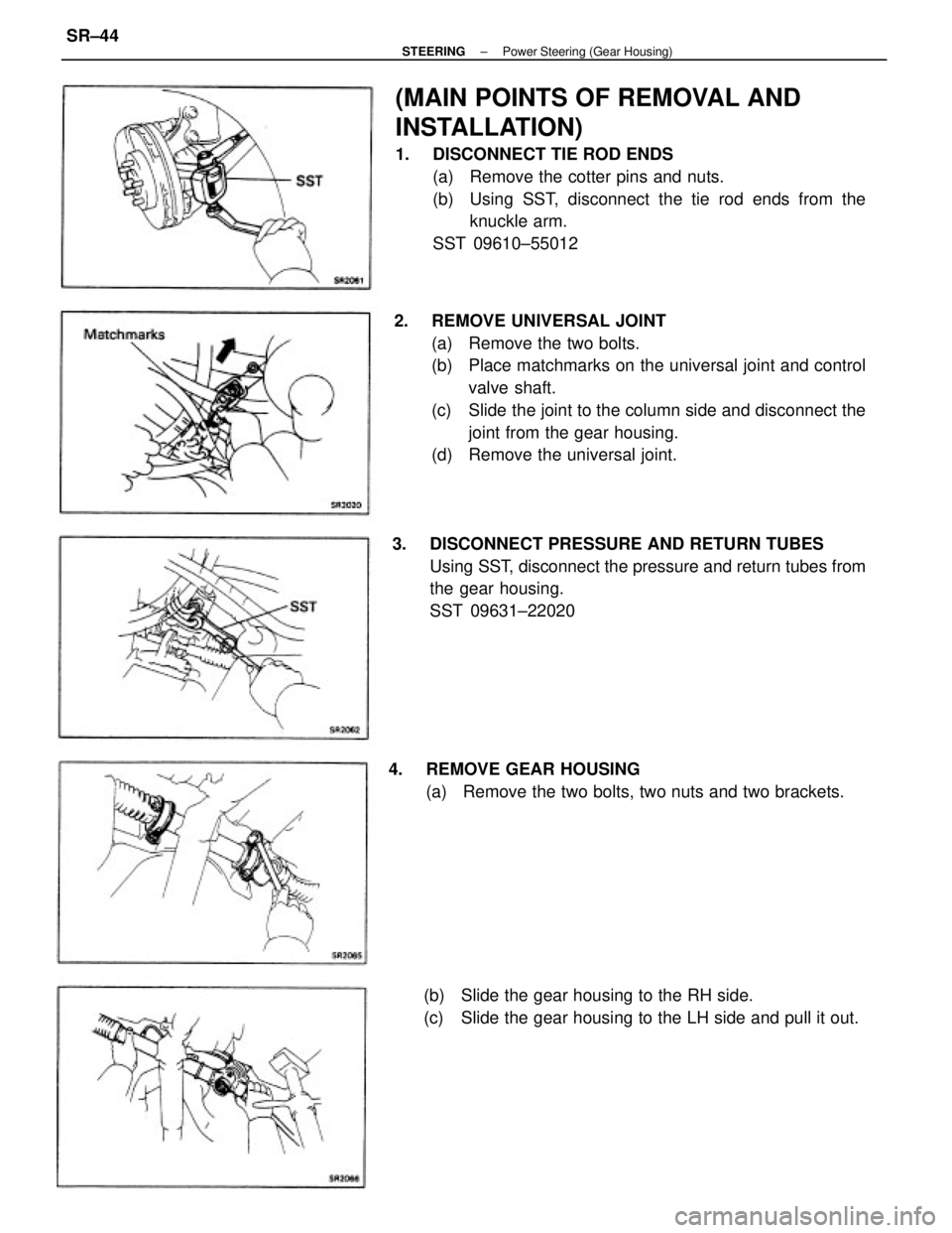
(MAIN POINTS OF REMOVAL AND
INSTALLATION)
1. DISCONNECT TIE ROD ENDS
(a) Remove the cotter pins and nuts.
(b) Using SST, disconnect the tie rod ends from the
knuckle arm.
SST 09610±55012
2. REMOVE UNIVERSAL JOINT
(a) Remove the two bolts.
(b) Place matchmarks on the universal joint and control
valve shaft.
(c) Slide the joint to the column side and disconnect the
joint from the gear housing.
(d) Remove the universal joint.
3. DISCONNECT PRESSURE AND RETURN TUBES
Using SST, disconnect the pressure and return tubes from
the gear housing.
SST 09631±22020
4. REMOVE GEAR HOUSING
(a) Remove the two bolts, two nuts and two brackets.
(b) Slide the gear housing to the RH side.
(c) Slide the gear housing to the LH side and pull it out.
± STEERINGPower Steering (Gear Housing)SR±44
Trending: adding oil, odometer, set clock, four wheel drive, brake light, charging, roof rack

![TOYOTA CAMRY V20 1986 Service Information (b) Check the flow control valve for leakage.
Close.one of the holes and apply compressed air [4
±5 kg/crn
2 (57 ± 71 psi, 392 ± 490 kPa)] into the oppo-
site side, and confirm that air does not c TOYOTA CAMRY V20 1986 Service Information (b) Check the flow control valve for leakage.
Close.one of the holes and apply compressed air [4
±5 kg/crn
2 (57 ± 71 psi, 392 ± 490 kPa)] into the oppo-
site side, and confirm that air does not c](/img/14/57449/w960_57449-2363.png)


