TOYOTA CAMRY V20 1986 Service Information
CAMRY V20 1986
TOYOTA
TOYOTA
https://www.carmanualsonline.info/img/14/57449/w960_57449-0.png
TOYOTA CAMRY V20 1986 Service Information
Trending: lock, battery location, rear view mirror, engine coolant, fuel tank capacity, display, engine overheat
Page 501 of 2389
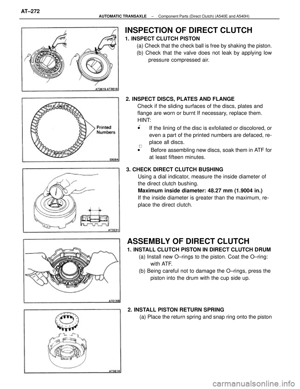
2. INSPECT DISCS, PLATES AND FLANGE
Check if the sliding surfaces of the discs, plates and
flange are worn or burnt If necessary, replace them.
HINT:
wIf the lining of the disc is exfoliated or discolored, or
even a part of the printed numbers are defaced, re-
place all discs.
w Before assembling new discs, soak them in ATF for
at least fifteen minutes.
ASSEMBLY OF DIRECT CLUTCH
1. INSTALL CLUTCH PISTON IN DIRECT CLUTCH DRUM
(a) Install new O±rings to the piston. Coat the O±ring:
with ATF.
(b) Being careful not to damage the O±rings, press the
piston into the drum with the cup side up.
INSPECTION OF DIRECT CLUTCH
1. INSPECT CLUTCH PISTON
(a) Check that the check ball is free by shaking the piston.
(b) Check that the valve does not leak by applying low
pressure compressed air.
3. CHECK DIRECT CLUTCH BUSHING
Using a dial indicator, measure the inside diameter of
the direct clutch bushing.
Maximum inside diameter: 48.27 mm (1.9004 in.)
If the inside diameter is greater than the maximum, re-
place the direct clutch.
2. INSTALL PISTON RETURN SPRING
(a) Place the return spring and snap ring onto the piston
± AUTOMATIC TRANSAXLEComponent Parts (Direct Clutch) (A540E and A540H)AT±272
Page 502 of 2389
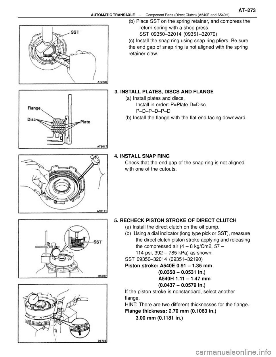
5. RECHECK PISTON STROKE OF DIRECT CLUTCH
(a) Install the direct clutch on the oil pump.
(b) Using a dial indicator (long type pick or SST), measure
the direct clutch piston stroke applying and releasing
the compressed air (4 ± 8 kg/Cm2, 57 ±
114 psi, 392 ± 785 kPa) as shown.
SST 09350±32014 (09351±32190)
Piston stroke: A540E 0.91 ± 1.35 mm
(0.0358 ± 0.0531 in.)
A540H 1.11 ± 1.47 mm
(0.0437 ± 0.0579 in.)
If the piston stroke is nonstandard, select another
flange.
HINT: There are two different thicknesses for the flange.
Flange thickness: 2.70 mm (0.1063 in.)
3.00 mm (0.1181 in.) (b) Place SST on the spring retainer, and compress the
return spring with a shop press.
SST 09350±32014 (09351±32070)
(c) Install the snap ring using snap ring pliers. Be sure
the end gap of snap ring is not aligned with the spring
retainer claw.
3. INSTALL PLATES, DISCS AND FLANGE
(a) Install plates and discs.
Install in order: P=Plate D=Disc
P±D±P±D±P±D
(b) Install the flange with the flat end facing downward.
4. INSTALL SNAP RING
Check that the end gap of the snap ring is not aligned
with one of the cutouts.
± AUTOMATIC TRANSAXLEComponent Parts (Direct Clutch) (A540E and A540H)AT±273
Page 503 of 2389
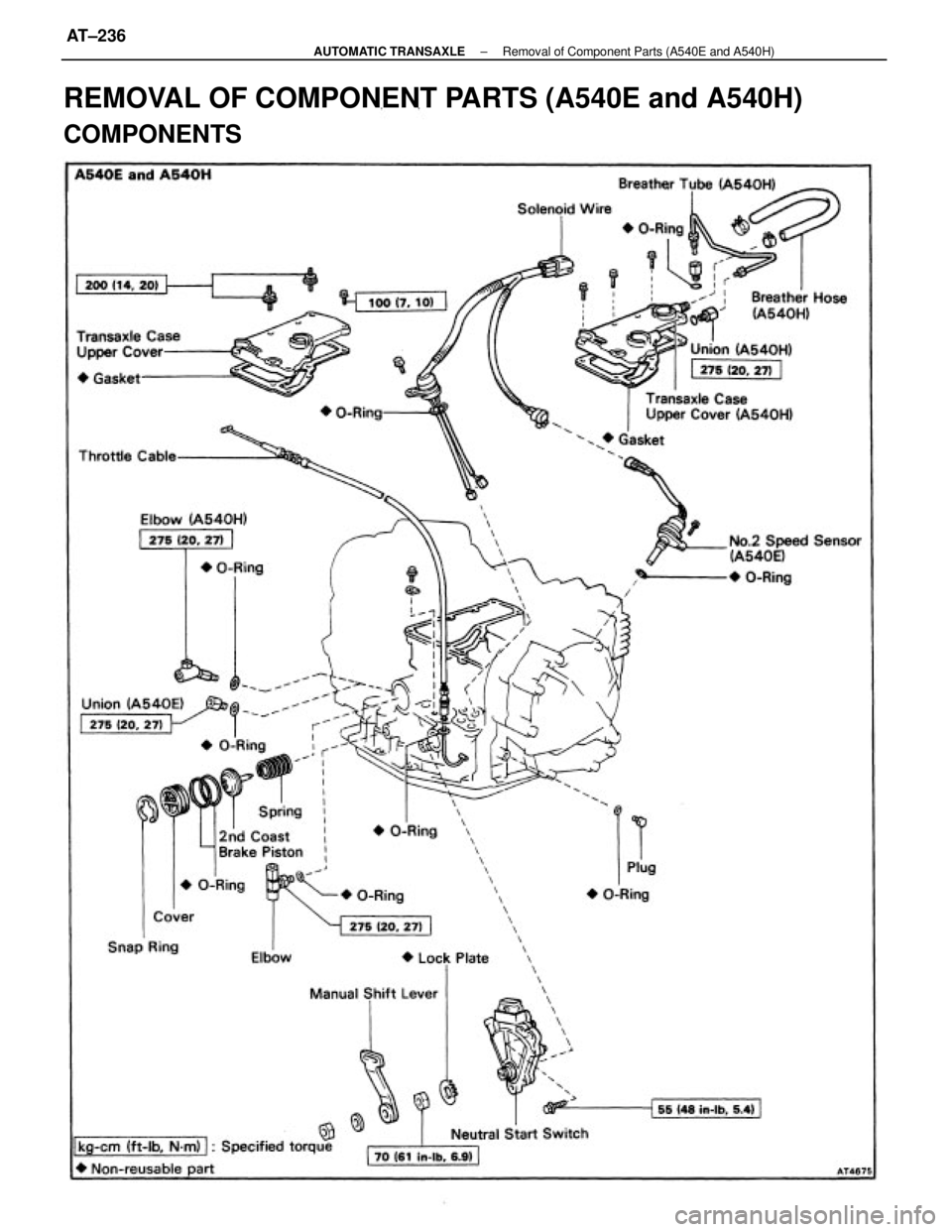
REMOVAL OF COMPONENT PARTS (A540E and A540H)
COMPONENTS
± AUTOMATIC TRANSAXLERemoval of Component Parts (A540E and A540H)AT±236
Page 504 of 2389
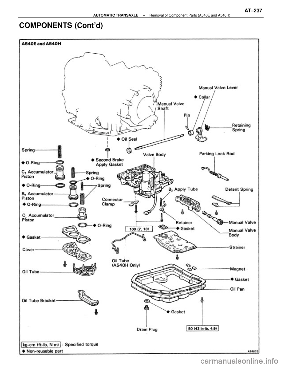
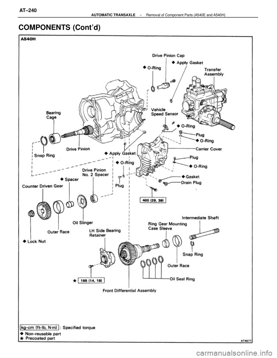
COMPONENTS (Cont'd)
± AUTOMATIC TRANSAXLERemoval of Component Parts (A540E and A540H)AT±237
Page 505 of 2389
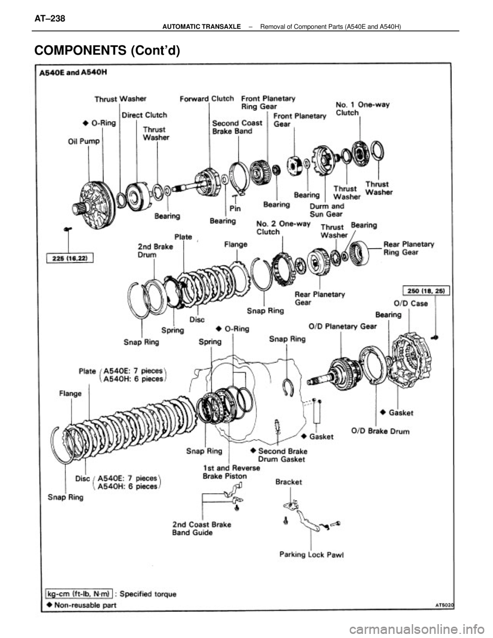
COMPONENTS (Cont'd)
± AUTOMATIC TRANSAXLERemoval of Component Parts (A540E and A540H)AT±238
Page 506 of 2389
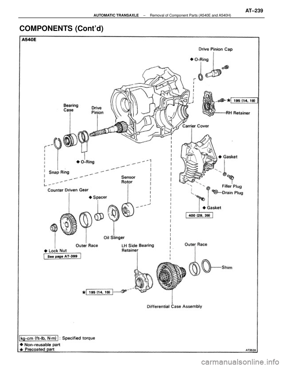
COMPONENTS (Cont'd)
± AUTOMATIC TRANSAXLERemoval of Component Parts (A540E and A540H)AT±239
Page 507 of 2389
COMPONENTS (Cont'd)
± AUTOMATIC TRANSAXLERemoval of Component Parts (A540E and A540H)AT±240
Page 508 of 2389
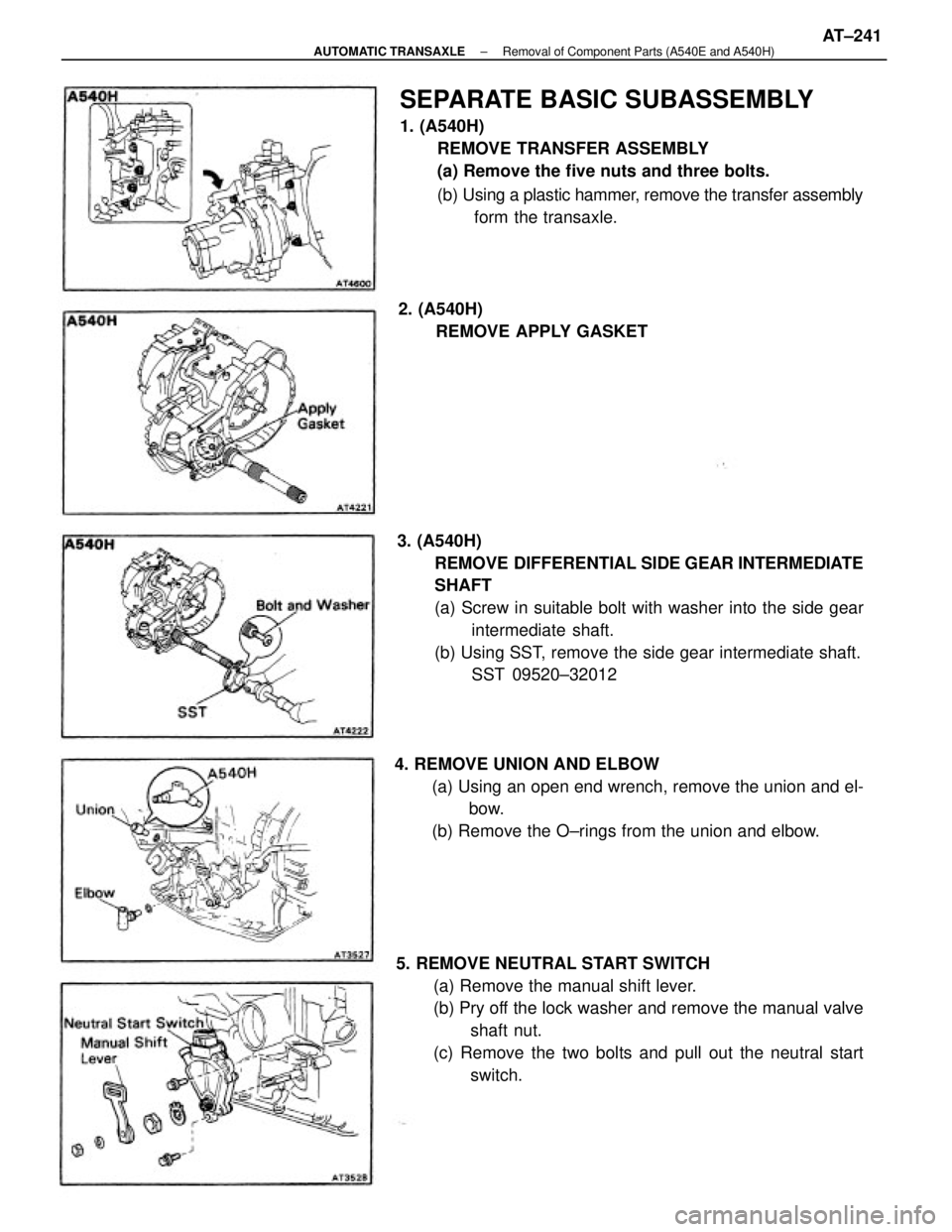
5. REMOVE NEUTRAL START SWITCH
(a) Remove the manual shift lever.
(b) Pry off the lock washer and remove the manual valve
shaft nut.
(c) Remove the two bolts and pull out the neutral start
switch. 3. (A540H)
REMOVE DIFFERENTIAL SIDE GEAR INTERMEDIATE
SHAFT
(a) Screw in suitable bolt with washer into the side gear
intermediate shaft.
(b) Using SST, remove the side gear intermediate shaft.
SST 09520±32012
SEPARATE BASIC SUBASSEMBLY
1. (A540H)
REMOVE TRANSFER ASSEMBLY
(a) Remove the five nuts and three bolts.
(b) Using a plastic hammer, remove the transfer assembly
form the transaxle.
4. REMOVE UNION AND ELBOW
(a) Using an open end wrench, remove the union and el-
bow.
(b) Remove the O±rings from the union and elbow. 2. (A540H)
REMOVE APPLY GASKET
± AUTOMATIC TRANSAXLERemoval of Component Parts (A540E and A540H)AT±241
Page 509 of 2389
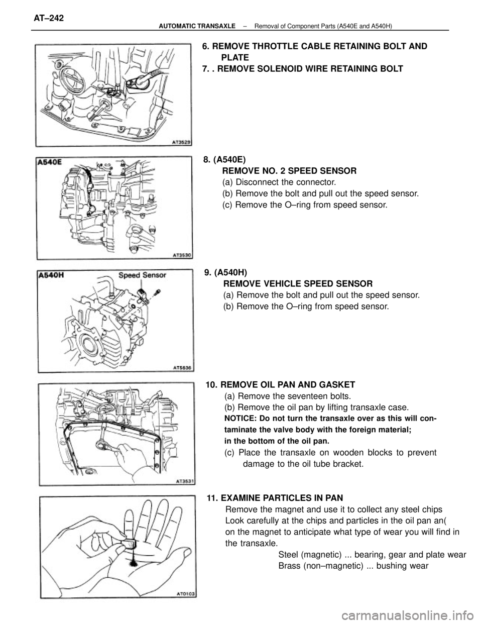
10. REMOVE OIL PAN AND GASKET
(a) Remove the seventeen bolts.
(b) Remove the oil pan by lifting transaxle case.
NOTICE: Do not turn the transaxle over as this will con-
taminate the valve body with the foreign material;
in the bottom of the oil pan.
(c) Place the transaxle on wooden blocks to prevent
damage to the oil tube bracket.
11. EXAMINE PARTICLES IN PAN
Remove the magnet and use it to collect any steel chips
Look carefully at the chips and particles in the oil pan an(
on the magnet to anticipate what type of wear you will find in
the transaxle.
Steel (magnetic) ... bearing, gear and plate wear
Brass (non±magnetic) ... bushing wear 8. (A540E)
REMOVE NO. 2 SPEED SENSOR
(a) Disconnect the connector.
(b) Remove the bolt and pull out the speed sensor.
(c) Remove the O±ring from speed sensor.
9. (A540H)
REMOVE VEHICLE SPEED SENSOR
(a) Remove the bolt and pull out the speed sensor.
(b) Remove the O±ring from speed sensor. 6. REMOVE THROTTLE CABLE RETAINING BOLT AND
PLATE
7. . REMOVE SOLENOID WIRE RETAINING BOLT
± AUTOMATIC TRANSAXLERemoval of Component Parts (A540E and A540H)AT±242
Page 510 of 2389
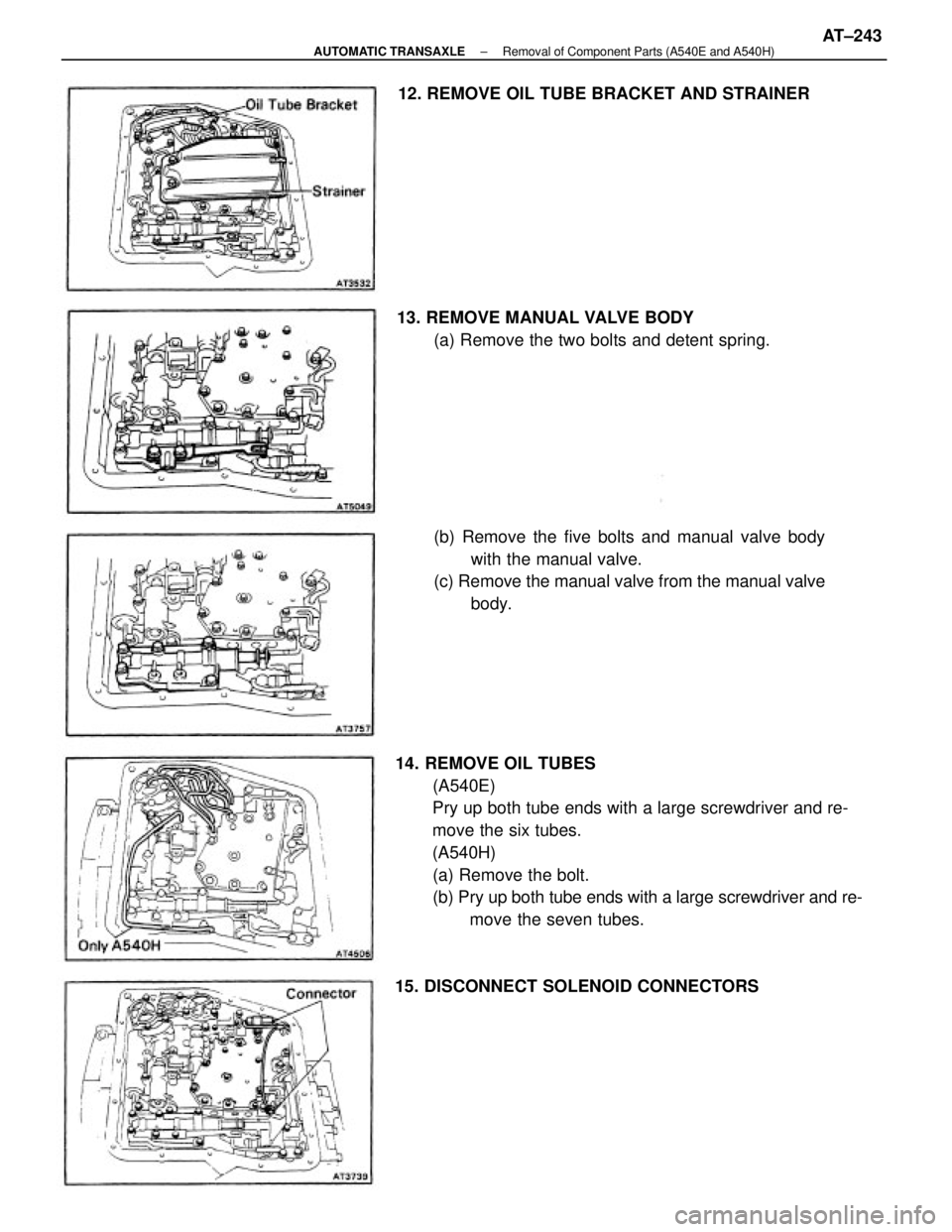
14. REMOVE OIL TUBES
(A540E)
Pry up both tube ends with a large screwdriver and re-
move the six tubes.
(A540H)
(a) Remove the bolt.
(b) Pry up both tube ends with a large screwdriver and re-
move the seven tubes. (b) Remove the five bolts and manual valve body
with the manual valve.
(c) Remove the manual valve from the manual valve
body. 13. REMOVE MANUAL VALVE BODY
(a) Remove the two bolts and detent spring. 12. REMOVE OIL TUBE BRACKET AND STRAINER
15. DISCONNECT SOLENOID CONNECTORS
± AUTOMATIC TRANSAXLERemoval of Component Parts (A540E and A540H)AT±243
Trending: alternator, fuse diagram, oil reset, catalytic converter, fuel tank capacity, brake sensor, washer fluid


