TOYOTA CAMRY V20 1986 Service Information
Manufacturer: TOYOTA, Model Year: 1986, Model line: CAMRY V20, Model: TOYOTA CAMRY V20 1986Pages: 2389, PDF Size: 84.44 MB
Page 471 of 2389
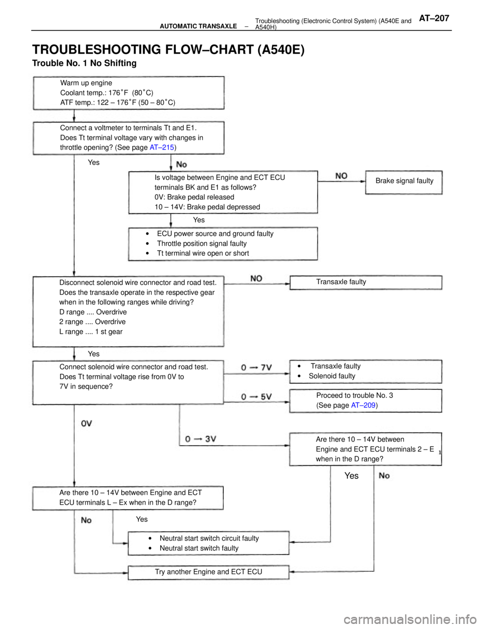
Disconnect solenoid wire connector and road test.
Does the transaxle operate in the respective gear
when in the following ranges while driving?
D range .... Overdrive
2 range .... Overdrive
L range .... 1 st gear
TROUBLESHOOTING FLOW±CHART (A540E)
Trouble No. 1 No Shifting
Is voltage between Engine and ECT ECU
terminals BK and E1 as follows?
0V: Brake pedal released
10 ± 14V: Brake pedal depressed
Connect solenoid wire connector and road test.
Does Tt terminal voltage rise from 0V to
7V in sequence?Warm up engine
Coolant temp.: 176°F (80°C)
ATF temp.: 122 ± 176°F (50 ± 80°C)
Connect a voltmeter to terminals Tt and E1.
Does Tt terminal voltage vary with changes in
throttle opening? (See page AT±215)
wECU power source and ground faulty
wThrottle position signal faulty
wTt terminal wire open or short
Are there 10 ± 14V between
Engine and ECT ECU terminals 2 ± E
when in the D range?
Are there 10 ± 14V between Engine and ECT
ECU terminals L ± Ex when in the D range?
wNeutral start switch circuit faulty
wNeutral start switch faultyProceed to trouble No. 3
(See page AT±209)
Try another Engine and ECT ECUw Transaxle faulty
wSolenoid faultyBrake signal faulty
Transaxle faulty
Ye s
Ye s
Ye s
Ye s Ye s
± AUTOMATIC TRANSAXLETroubleshooting (Electronic Control System) (A540E and
A540H)AT±207
Page 472 of 2389
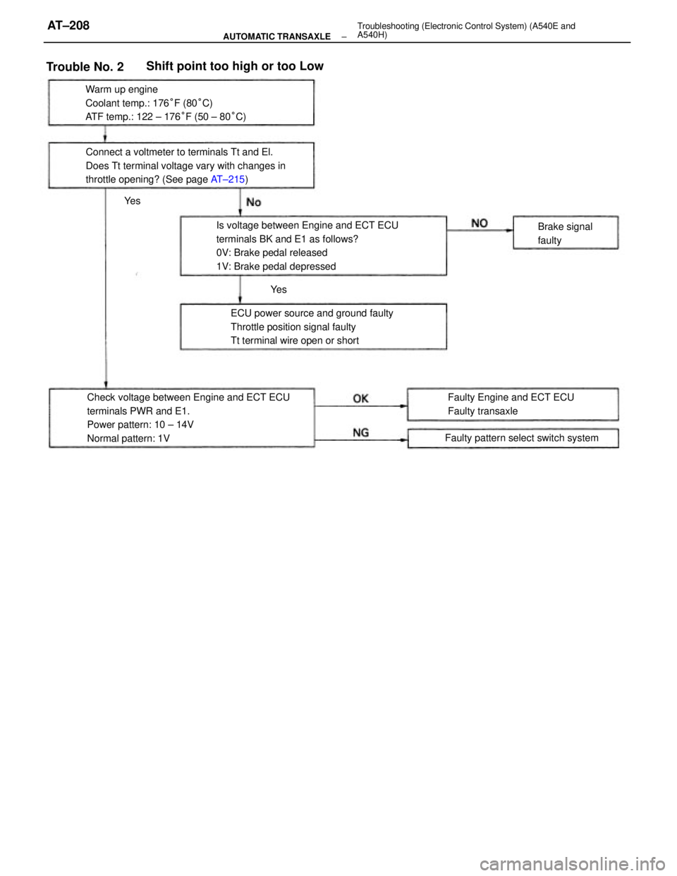
Check voltage between Engine and ECT ECU
terminals PWR and E1.
Power pattern: 10 ± 14V
Normal pattern: 1VIs voltage between Engine and ECT ECU
terminals BK and E1 as follows?
0V: Brake pedal released
1V: Brake pedal depressed Warm up engine
Coolant temp.: 176°F (80°C)
ATF temp.: 122 ± 176°F (50 ± 80°C)
Connect a voltmeter to terminals Tt and El.
Does Tt terminal voltage vary with changes in
throttle opening? (See page AT±215)
ECU power source and ground faulty
Throttle position signal faulty
Tt terminal wire open or short
Faulty Engine and ECT ECU
Faulty transaxle
Shift point too high or too Low
Faulty pattern select switch systemBrake signal
faulty
Trouble No. 2
Ye s Ye s
± AUTOMATIC TRANSAXLETroubleshooting (Electronic Control System) (A540E and
A540H)AT±208
Page 473 of 2389
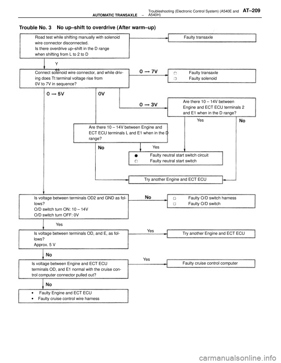
Is voltage between terminals OD2 and GND as fol-
lows?
O/D switch turn ON: 10 ± 14V
O/D switch turn OFF: 0VRoad test while shifting manually with solenoid
wire connector disconnected.
Is there overdrive up±shift in the D range
when shifting from L to 2 to D
Is voltage between Engine and ECT ECU
terminals OD, and E1 normal with the cruise con-
trol computer connector pulled out?Connect solenoid wire connector, and while driv-
ing does Tt terminal voltage rise from
0V to 7V in sequence?
Is voltage between terminals OD, and E, as fol-
lows?
Approx. 5 VAre there 10 ± 14V between Engine and
ECT ECU terminals L and E1 when in the D
range?
No up±shift to overdrive (After warm±up)
Are there 10 ± 14V between
Engine and ECT ECU terminals 2
and E1 when in the D range?
w Faulty Engine and ECT ECU
wFaulty cruise control wire harnessFaulty neutral start switch circuit
Faulty neutral start switch
Faulty O/D switch harness
Faulty O/D switch Try another Engine and ECT ECU
Try another Engine and ECT ECU
Faulty cruise control computerFaulty transaxle
Faulty solenoid Faulty transaxle
Trouble No. 3
Y
es
Ye s
Ye sYe s
Ye s Ye s
± AUTOMATIC TRANSAXLETroubleshooting (Electronic Control System) (A540E and
A540H)AT±209
Page 474 of 2389
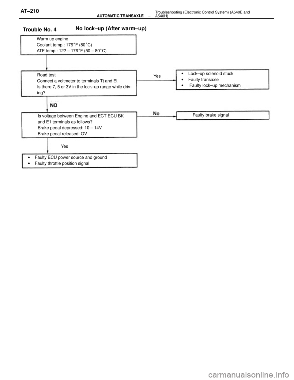
Road test
Connect a voltmeter to terminals Tt and El.
Is there 7, 5 or 3V in the lock±up range while driv-
ing?
Is voltage between Engine and ECT ECU BK
and E1 terminals as follows?
Brake pedal depressed: 10 ± 14V
Brake pedal released: OV Warm up engine
Coolant temp.: 176°F (80°C)
ATF temp.: 122 ± 176°F (50 ± 80°C)
wFaulty ECU power source and ground
wFaulty throttle position signalwLock±up solenoid stuck
wFaulty transaxle
w Faulty lock±up mechanism
No lock±up (After warm±up)
Faulty brake signal
Trouble No. 4
Ye sYe s
± AUTOMATIC TRANSAXLETroubleshooting (Electronic Control System) (A540E and
A540H)AT±210
Page 475 of 2389
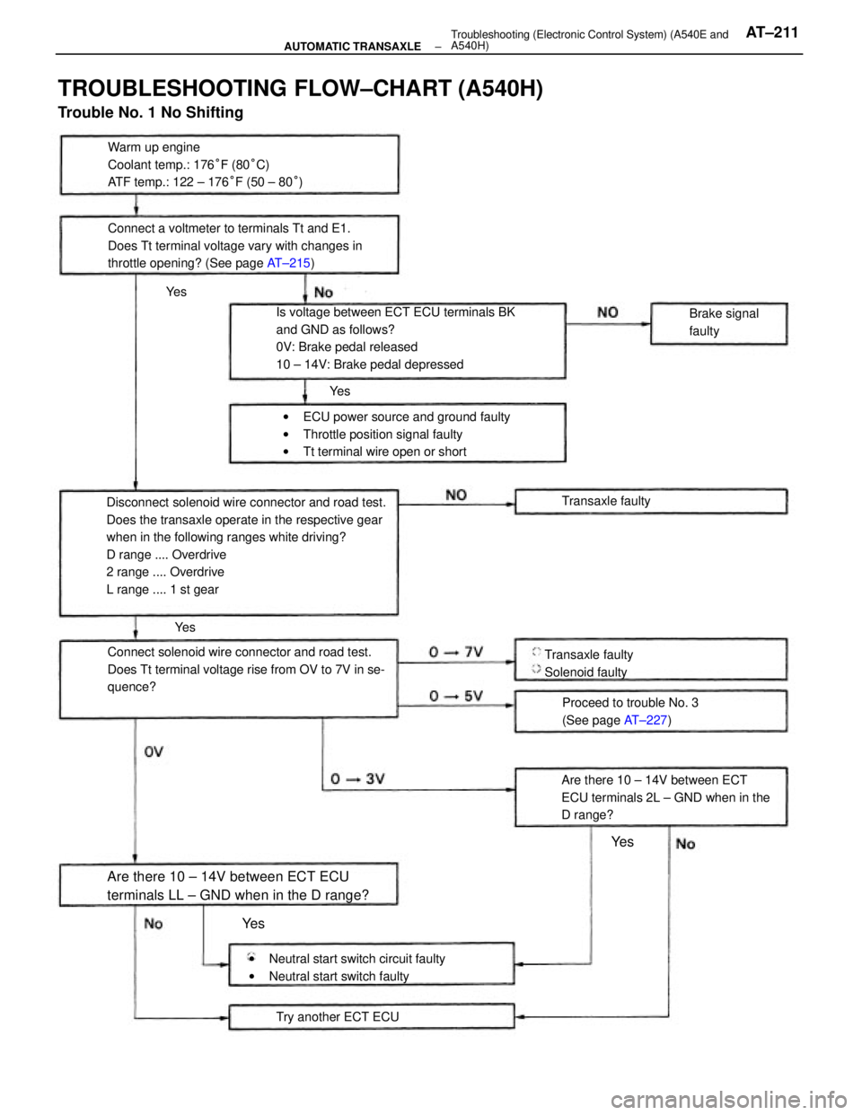
Disconnect solenoid wire connector and road test.
Does the transaxle operate in the respective gear
when in the following ranges white driving?
D range .... Overdrive
2 range .... Overdrive
L range .... 1 st gear
TROUBLESHOOTING FLOW±CHART (A540H)
Trouble No. 1 No Shifting
Is voltage between ECT ECU terminals BK
and GND as follows?
0V: Brake pedal released
10 ± 14V: Brake pedal depressed
Connect solenoid wire connector and road test.
Does Tt terminal voltage rise from OV to 7V in se-
quence?Warm up engine
Coolant temp.: 176°F (80°C)
ATF temp.: 122 ± 176°F (50 ± 80°)
Connect a voltmeter to terminals Tt and E1.
Does Tt terminal voltage vary with changes in
throttle opening? (See page AT±215)
wECU power source and ground faulty
wThrottle position signal faulty
wTt terminal wire open or short
Are there 10 ± 14V between ECT
ECU terminals 2L ± GND when in the
D range?
Are there 10 ± 14V between ECT ECU
terminals LL ± GND when in the D range?
wNeutral start switch circuit faulty
wNeutral start switch faultyProceed to trouble No. 3
(See page AT±227) Transaxle faulty
Solenoid faulty
Try another ECT ECUBrake signal
faulty
Transaxle faulty
Ye s
Ye s
Ye s Ye s
Ye s
± AUTOMATIC TRANSAXLETroubleshooting (Electronic Control System) (A540E and
A540H)AT±211
Page 476 of 2389
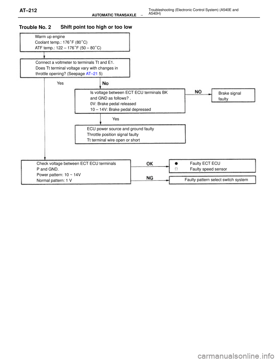
Is voltage between ECT ECU terminals BK
and GND as follows? .
0V: Brake pedal released
10 ± 14V: Brake pedal depressed
Check voltage between ECT ECU terminals
P and GND.
Power pattern: 10 ~ 14V
Normal pattern: 1 V Warm up engine
Coolant temp.: 176°F (80°C)
ATF temp.: 122 ± 176°F (50 ± 80°C)
Connect a voltmeter to terminals Tt and E1.
Does Tt terminal voltage vary with changes in
throttle opening? (Seepage AT±21 5)
ECU power source and ground faulty
Throttle position signal faulty
Tt terminal wire open or short
Faulty pattern select switch system
Shift point too high or too low
Faulty ECT ECU
Faulty speed sensorBrake signal
faulty
Trouble No. 2
Ye s
Ye s
± AUTOMATIC TRANSAXLETroubleshooting (Electronic Control System) (A540E and
A540H)AT±212
Page 477 of 2389
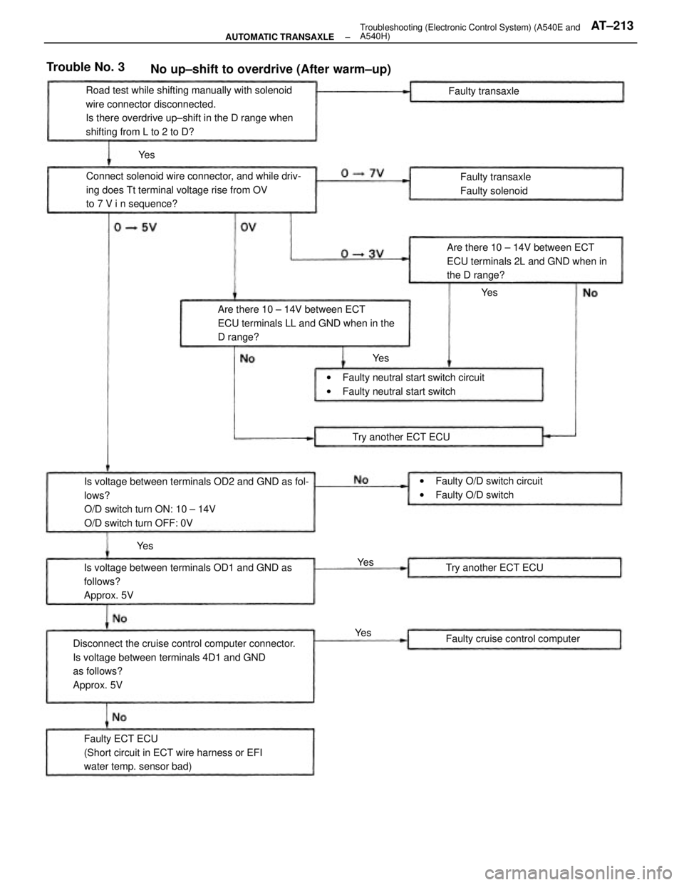
Disconnect the cruise control computer connector.
Is voltage between terminals 4D1 and GND
as follows?
Approx. 5VIs voltage between terminals OD2 and GND as fol-
lows?
O/D switch turn ON: 10 ± 14V
O/D switch turn OFF: 0VRoad test while shifting manually with solenoid
wire connector disconnected.
Is there overdrive up±shift in the D range when
shifting from L to 2 to D?
Is voltage between terminals OD1 and GND as
follows?
Approx. 5VConnect solenoid wire connector, and while driv-
ing does Tt terminal voltage rise from OV
to 7 V i n sequence?
Faulty ECT ECU
(Short circuit in ECT wire harness or EFI
water temp. sensor bad)Are there 10 ± 14V between ECT
ECU terminals LL and GND when in the
D range?
No up±shift to overdrive (After warm±up)
Are there 10 ± 14V between ECT
ECU terminals 2L and GND when in
the D range?
wFaulty neutral start switch circuit
wFaulty neutral start switch
wFaulty O/D switch circuit
wFaulty O/D switch
Faulty cruise control computerFaulty transaxle
Faulty solenoid
Try another ECT ECU Try another ECT ECUFaulty transaxle
Trouble No. 3
Ye sYe s
Ye s
Ye sYe s Ye s
± AUTOMATIC TRANSAXLETroubleshooting (Electronic Control System) (A540E and
A540H)AT±213
Page 478 of 2389
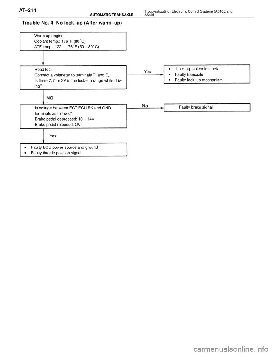
Road test
Connect a voltmeter to terminals Tt and E,.
Is there 7, 5 or 3V in the lock±up range while driv-
ing?
Is voltage between ECT ECU BK and GND
terminals as follows?
Brake pedal depressed: 10 ± 14V
Brake pedal released: OV Warm up engine
Coolant temp.: 176°F (80°C)
ATF temp.: 122 ± 176°F (50 ± 80°C)
Trouble No. 4 No lock±up (After warm±up)
w Lock±up solenoid stuck
wFaulty transaxle
wFaulty lock±up mechanism
wFaulty ECU power source and ground
wFaulty throttle position signalFaulty brake signal
Ye sYe s
± AUTOMATIC TRANSAXLETroubleshooting (Electronic Control System) (A540E and
A540H)AT±214
Page 479 of 2389
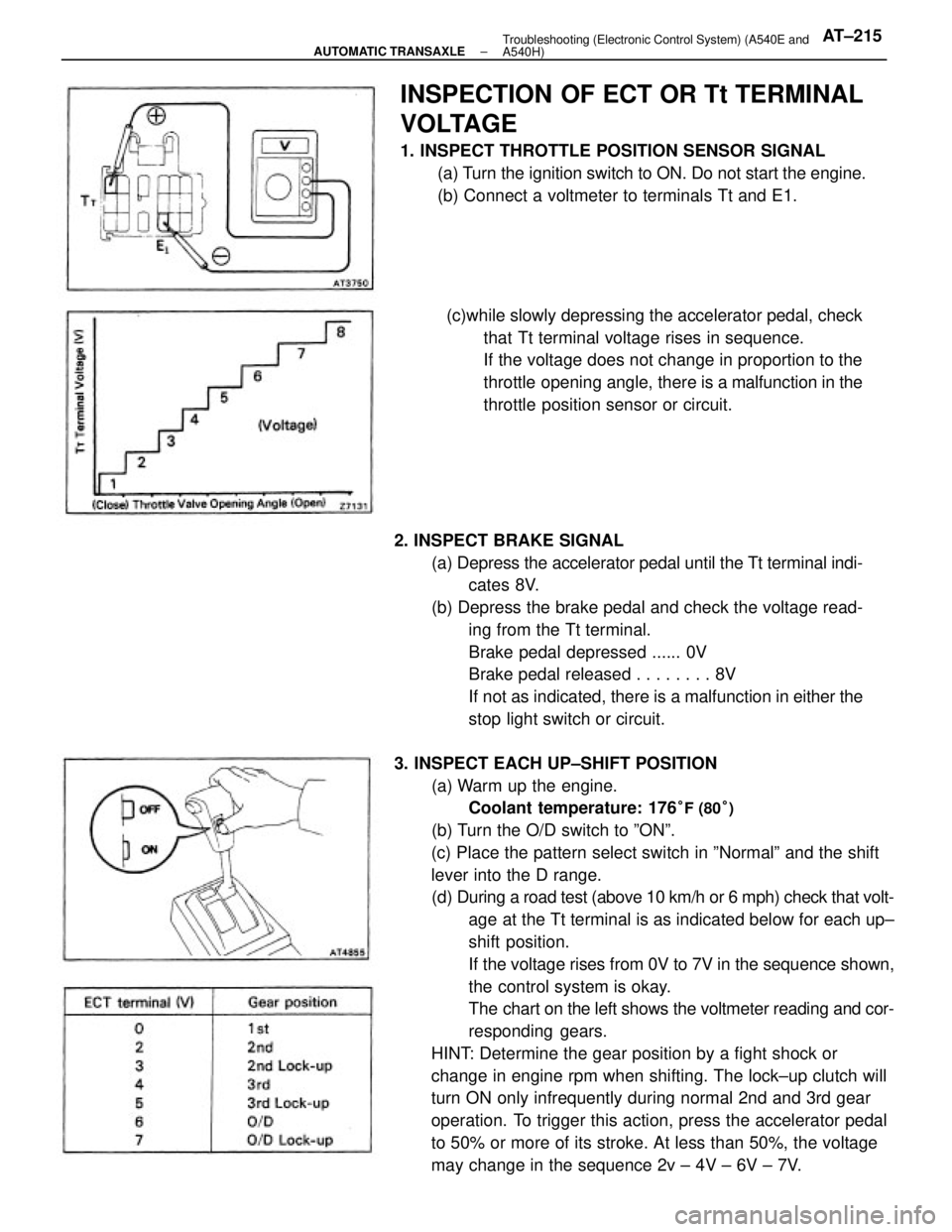
3. INSPECT EACH UP±SHIFT POSITION
(a) Warm up the engine.
Coolant temperature: 176
°F (80°)
(b) Turn the O/D switch to ºONº.
(c) Place the pattern select switch in ºNormalº and the shift
lever into the D range.
(d) During a road test (above 10 km/h or 6 mph) check that volt-
age at the Tt terminal is as indicated below for each up±
shift position.
If the voltage rises from 0V to 7V in the sequence shown,
the control system is okay.
The chart on the left shows the voltmeter reading and cor-
responding gears.
HINT: Determine the gear position by a fight shock or
change in engine rpm when shifting. The lock±up clutch will
turn ON only infrequently during normal 2nd and 3rd gear
operation. To trigger this action, press the accelerator pedal
to 50% or more of its stroke. At less than 50%, the voltage
may change in the sequence 2v ± 4V ± 6V ± 7V. 2. INSPECT BRAKE SIGNAL
(a) Depress the accelerator pedal until the Tt terminal indi-
cates 8V.
(b) Depress the brake pedal and check the voltage read-
ing from the Tt terminal.
Brake pedal depressed ...... 0V
Brake pedal released . . . . . . . . 8V
If not as indicated, there is a malfunction in either the
stop light switch or circuit.
INSPECTION OF ECT OR Tt TERMINAL
VOLTAGE
1. INSPECT THROTTLE POSITION SENSOR SIGNAL
(a) Turn the ignition switch to ON. Do not start the engine.
(b) Connect a voltmeter to terminals Tt and E1.
(c)while slowly depressing the accelerator pedal, check
that Tt terminal voltage rises in sequence.
If the voltage does not change in proportion to the
throttle opening angle, there is a malfunction in the
throttle position sensor or circuit.
± AUTOMATIC TRANSAXLETroubleshooting (Electronic Control System) (A540E and
A540H)AT±215
Page 480 of 2389
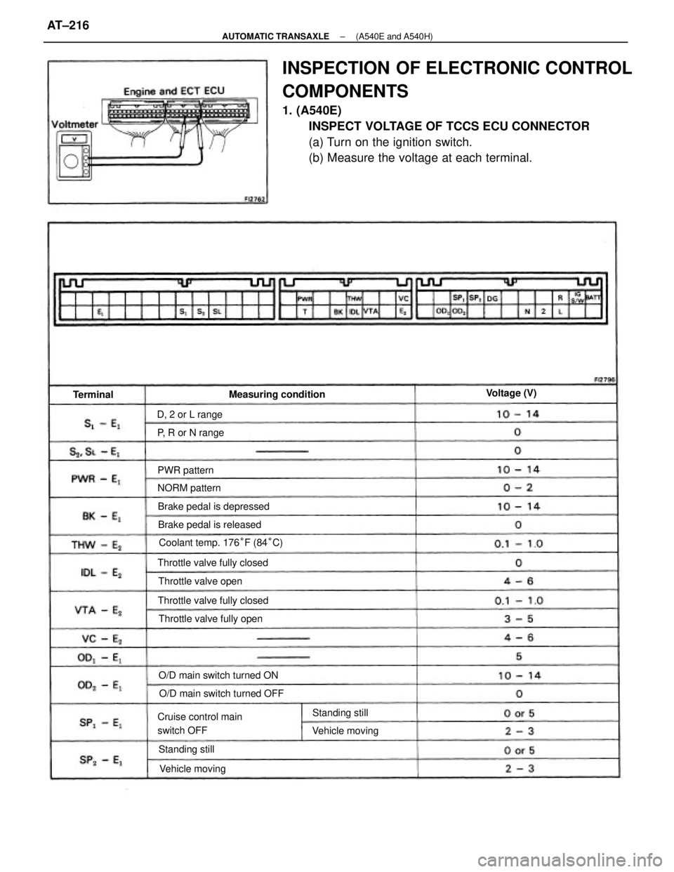
INSPECTION OF ELECTRONIC CONTROL
COMPONENTS
1. (A540E)
INSPECT VOLTAGE OF TCCS ECU CONNECTOR
(a) Turn on the ignition switch.
(b) Measure the voltage at each terminal.
Coolant temp. 176°F (84°C)
Cruise control main
switch OFFO/D main switch turned OFF O/D main switch turned ON Throttle valve fully closed
Throttle valve fully closed Brake pedal is depressed
Throttle valve fully openMeasuring condition
Brake pedal is released
Throttle valve open
Vehicle movingVehicle moving P, R or N range D, 2 or L range
Standing stillStanding still NORM patternVoltage (V)
PWR pattern Terminal
± AUTOMATIC TRANSAXLE(A540E and A540H)AT±216