TOYOTA CAMRY V20 1986 Service Information
CAMRY V20 1986
TOYOTA
TOYOTA
https://www.carmanualsonline.info/img/14/57449/w960_57449-0.png
TOYOTA CAMRY V20 1986 Service Information
Trending: tires, differential, park assist, jump cable, wheel alignment, oil temperature, airbag
Page 521 of 2389
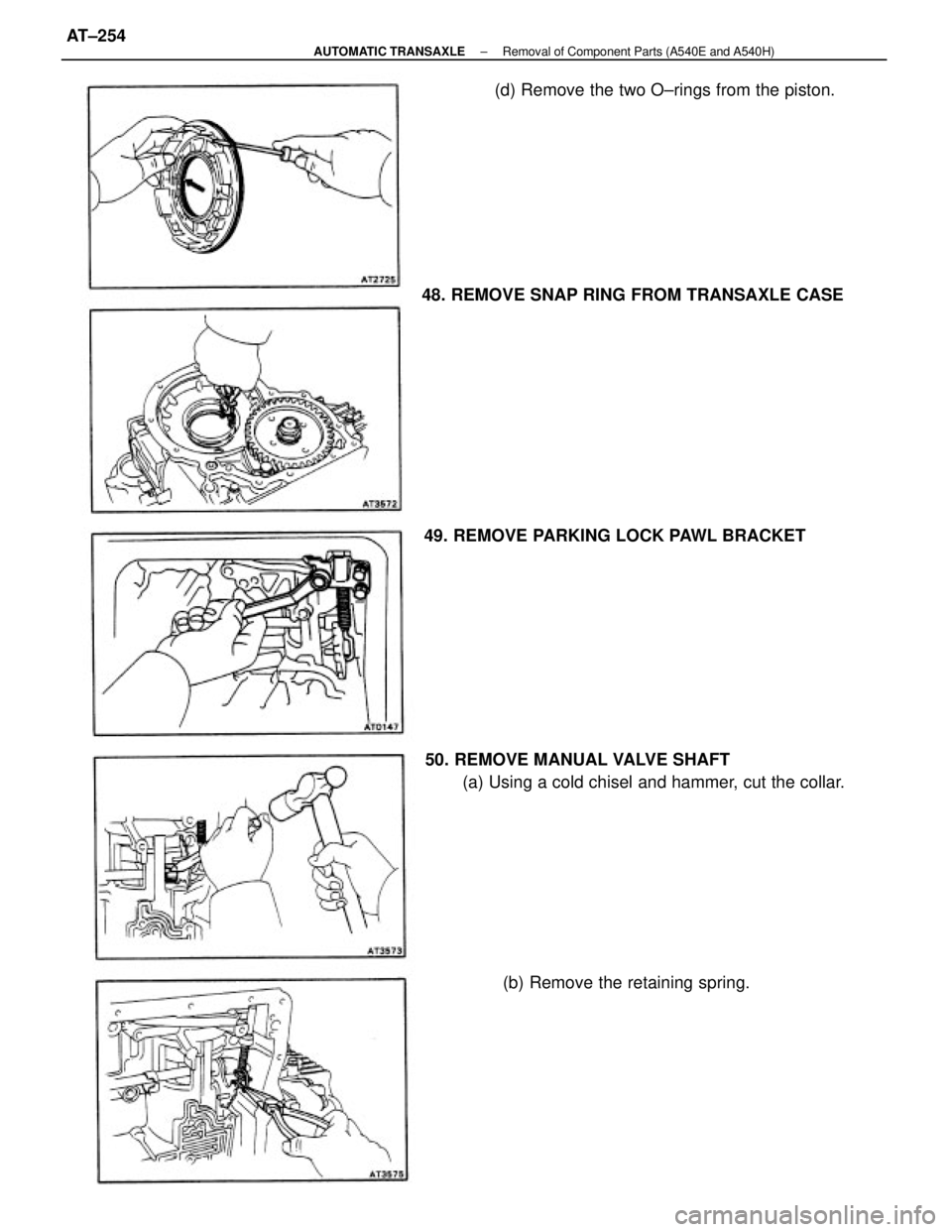
50. REMOVE MANUAL VALVE SHAFT
(a) Using a cold chisel and hammer, cut the collar. 48. REMOVE SNAP RING FROM TRANSAXLE CASE
49. REMOVE PARKING LOCK PAWL BRACKET(d) Remove the two O±rings from the piston.
(b) Remove the retaining spring.
± AUTOMATIC TRANSAXLERemoval of Component Parts (A540E and A540H)AT±254
Page 522 of 2389
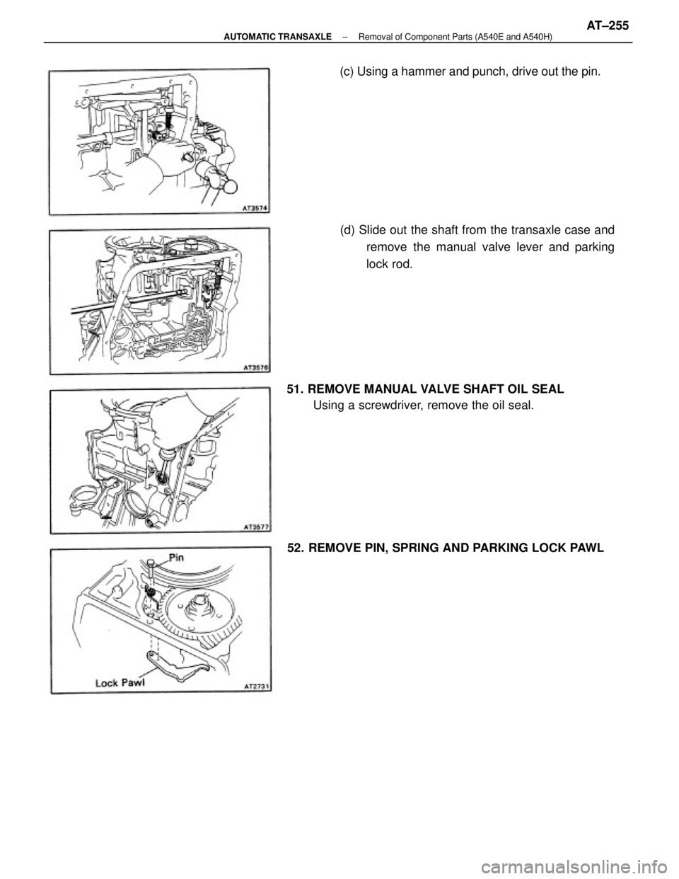
51. REMOVE MANUAL VALVE SHAFT OIL SEAL
Using a screwdriver, remove the oil seal.(d) Slide out the shaft from the transaxle case and
remove the manual valve lever and parking
lock rod. (c) Using a hammer and punch, drive out the pin.
52. REMOVE PIN, SPRING AND PARKING LOCK PAWL
± AUTOMATIC TRANSAXLERemoval of Component Parts (A540E and A540H)AT±255
Page 523 of 2389
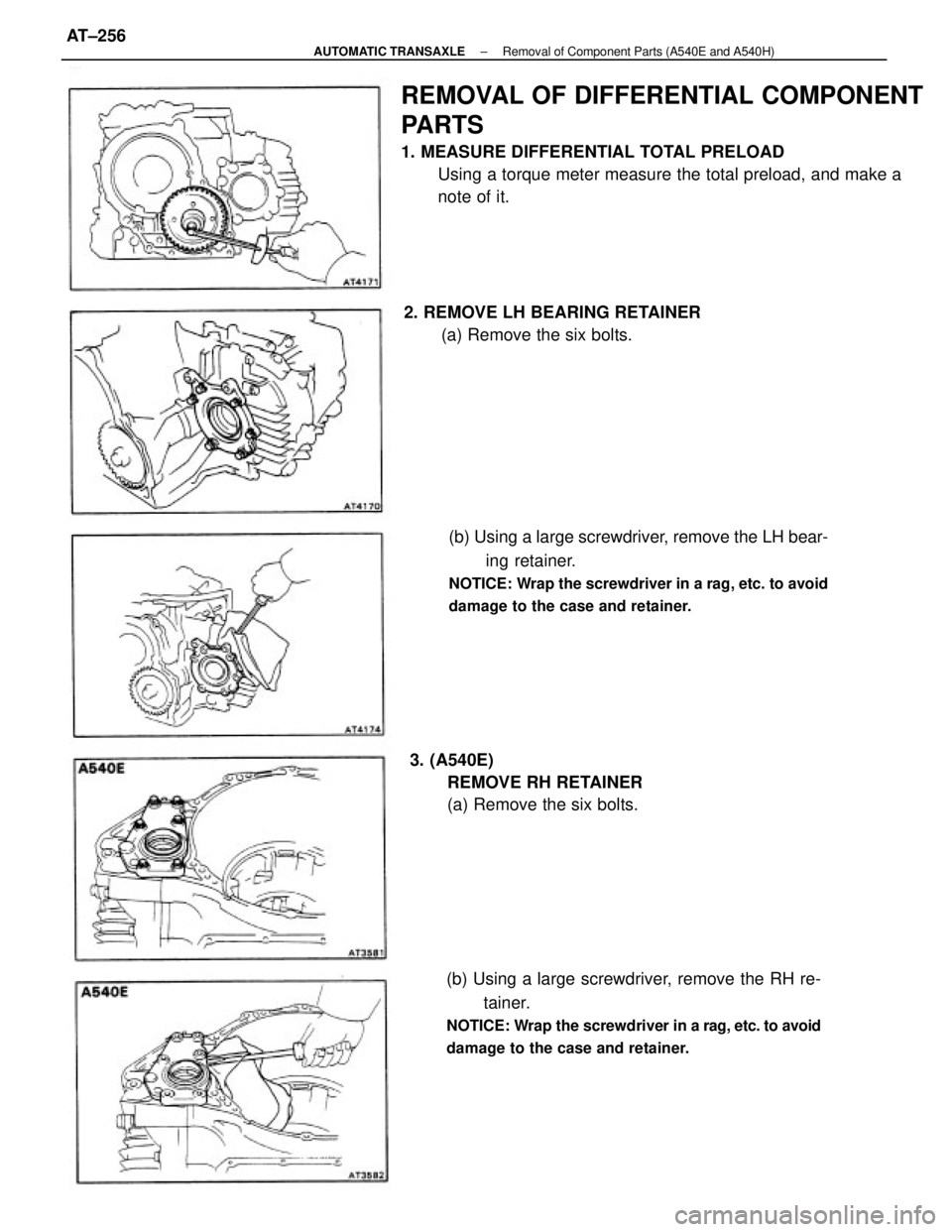
REMOVAL OF DIFFERENTIAL COMPONENT
PARTS
1. MEASURE DIFFERENTIAL TOTAL PRELOAD
Using a torque meter measure the total preload, and make a
note of it.
(b) Using a large screwdriver, remove the LH bear-
ing retainer.
NOTICE: Wrap the screwdriver in a rag, etc. to avoid
damage to the case and retainer.
(b) Using a large screwdriver, remove the RH re-
tainer.
NOTICE: Wrap the screwdriver in a rag, etc. to avoid
damage to the case and retainer.
2. REMOVE LH BEARING RETAINER
(a) Remove the six bolts.
3. (A540E)
REMOVE RH RETAINER
(a) Remove the six bolts.
± AUTOMATIC TRANSAXLERemoval of Component Parts (A540E and A540H)AT±256
Page 524 of 2389
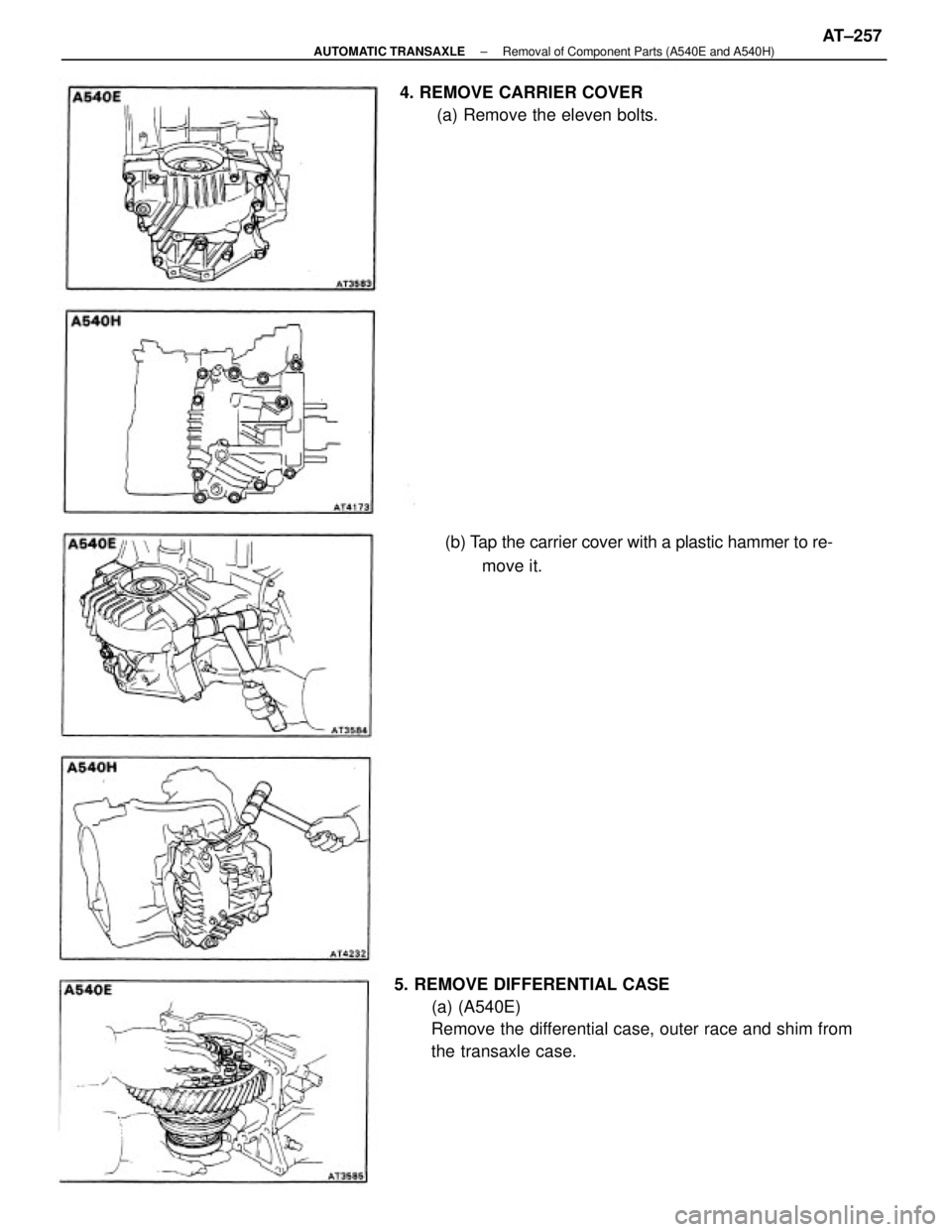
5. REMOVE DIFFERENTIAL CASE
(a) (A540E)
Remove the differential case, outer race and shim from
the transaxle case.(b) Tap the carrier cover with a plastic hammer to re-
move it. 4. REMOVE CARRIER COVER
(a) Remove the eleven bolts.
± AUTOMATIC TRANSAXLERemoval of Component Parts (A540E and A540H)AT±257
Page 525 of 2389
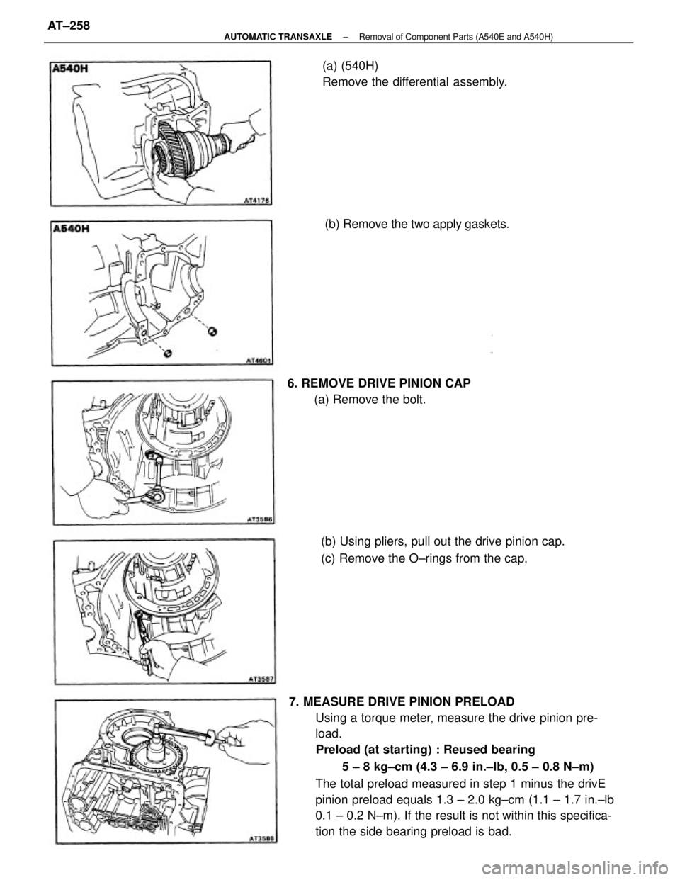
7. MEASURE DRIVE PINION PRELOAD
Using a torque meter, measure the drive pinion pre-
load.
Preload (at starting) : Reused bearing
5 ± 8 kg±cm (4.3 ± 6.9 in.±lb, 0.5 ± 0.8 N±m)
The total preload measured in step 1 minus the drivE
pinion preload equals 1.3 ± 2.0 kg±cm (1.1 ± 1.7 in.±lb
0.1 ± 0.2 N±m). If the result is not within this specifica-
tion the side bearing preload is bad.(b) Using pliers, pull out the drive pinion cap.
(c) Remove the O±rings from the cap. 6. REMOVE DRIVE PINION CAP
(a) Remove the bolt.(a) (540H)
Remove the differential assembly.
(b) Remove the two apply gaskets.
± AUTOMATIC TRANSAXLERemoval of Component Parts (A540E and A540H)AT±258
Page 526 of 2389
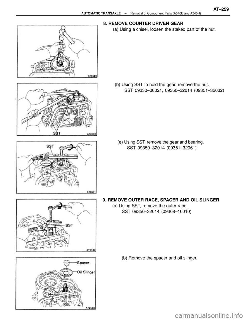
9. REMOVE OUTER RACE, SPACER AND OIL SLINGER
(a) Using SST, remove the outer race.
SST 09350±32014 (09308±10010) 8. REMOVE COUNTER DRIVEN GEAR
(a) Using a chisel, loosen the staked part of the nut.
(b) Using SST to hold the gear, remove the nut.
SST 09330±00021, 09350±32014 (09351±32032)
(e) Using SST, remove the gear and bearing.
SST 09350±32014 (09351±32061)
(b) Remove the spacer and oil slinger.
± AUTOMATIC TRANSAXLERemoval of Component Parts (A540E and A540H)AT±259
Page 527 of 2389
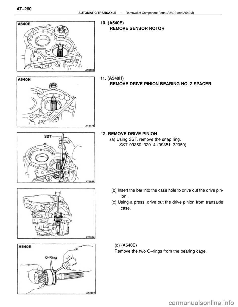
(b) Insert the bar into the case hole to drive out the drive pin-
ion.
(c) Using a press, drive out the drive pinion from transaxle
case. 11. (A540H)
REMOVE DRIVE PINION BEARING NO. 2 SPACER
12. REMOVE DRIVE PINION
(a) Using SST, remove the snap ring.
SST 09350±32014 (09351±32050)
(d) (A540E)
Remove the two O±rings from the bearing cage. 10. (A540E)
REMOVE SENSOR ROTOR
± AUTOMATIC TRANSAXLERemoval of Component Parts (A540E and A540M)AT±260
Page 528 of 2389
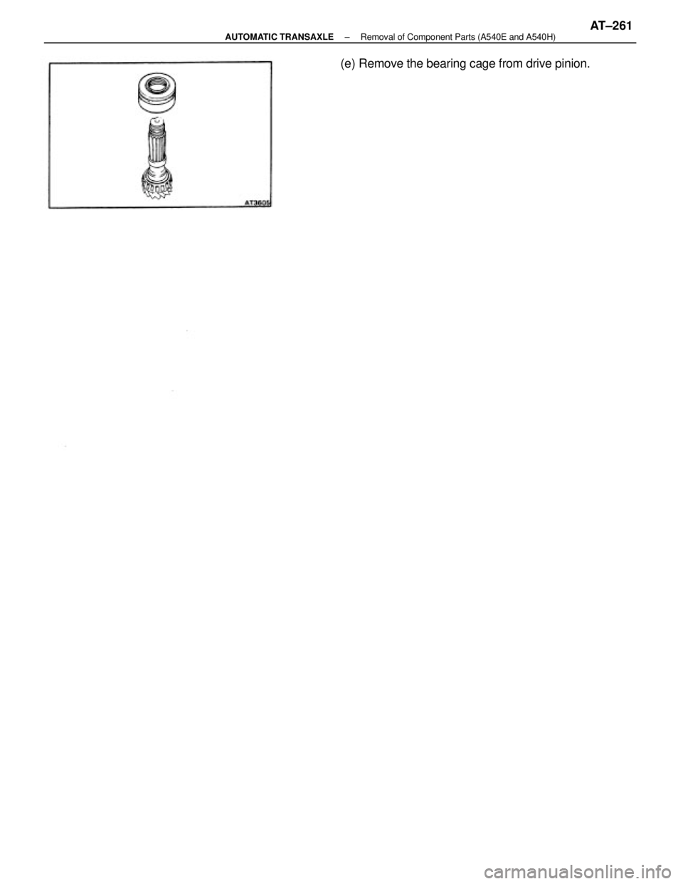
(e) Remove the bearing cage from drive pinion.
± AUTOMATIC TRANSAXLERemoval of Component Parts (A540E and A540H)AT±261
Page 529 of 2389
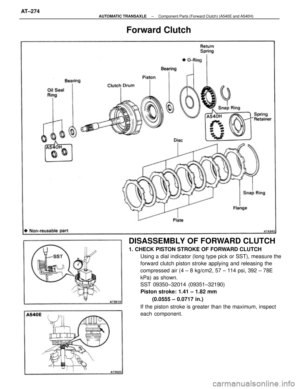
DISASSEMBLY OF FORWARD CLUTCH
1. CHECK PISTON STROKE OF FORWARD CLUTCH
Using a dial indicator (long type pick or SST), measure the
forward clutch piston stroke applying and releasing the
compressed air (4 ± 8 kg/cm2, 57 ± 114 psi, 392 ± 78E
kPa) as shown.
SST 09350±32014 (09351±32190)
Piston stroke: 1.41 ± 1.82 mm
(0.0555 ± 0.0717 in.)
If the piston stroke is greater than the maximum, inspect
each component.
Forward Clutch
± AUTOMATIC TRANSAXLEComponent Parts (Forward Clutch) (A540E and A540H)AT±274
Page 530 of 2389
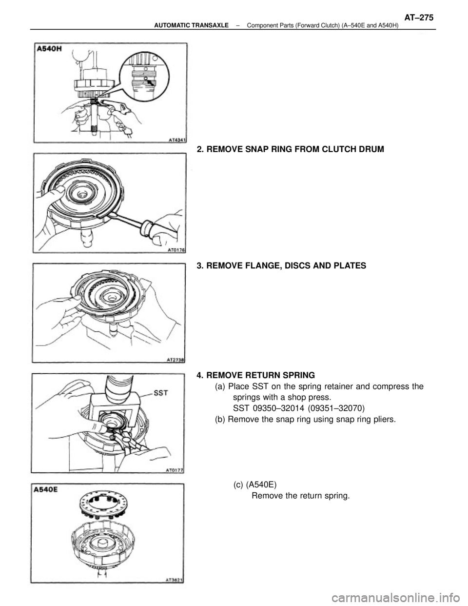
4. REMOVE RETURN SPRING
(a) Place SST on the spring retainer and compress the
springs with a shop press.
SST 09350±32014 (09351±32070)
(b) Remove the snap ring using snap ring pliers. 2. REMOVE SNAP RING FROM CLUTCH DRUM
(c) (A540E)
Remove the return spring. 3. REMOVE FLANGE, DISCS AND PLATES
± AUTOMATIC TRANSAXLEComponent Parts (Forward Clutch) (A±540E and A540H)AT±275
Trending: coolant, brake fluid, battery location, turn signal, window, air bleeding, lock
