TOYOTA CAMRY V20 1986 Service Information
CAMRY V20 1986
TOYOTA
TOYOTA
https://www.carmanualsonline.info/img/14/57449/w960_57449-0.png
TOYOTA CAMRY V20 1986 Service Information
Trending: sensor, 4WD, open gas tank, audio, fuel tank removal, height, trunk release
Page 681 of 2389
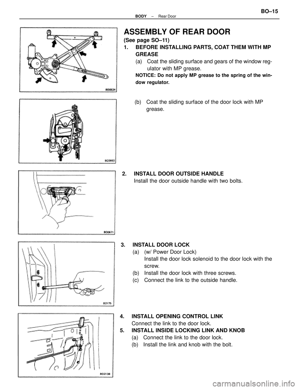
ASSEMBLY OF REAR DOOR
(See page SO±11)
1. BEFORE INSTALLING PARTS, COAT THEM WITH MP
GREASE
(a) Coat the sliding surface and gears of the window reg-
ulator with MP grease.
NOTICE: Do not apply MP grease to the spring of the win-
dow regulator.
3. INSTALL DOOR LOCK
(a) (w/ Power Door Lock)
Install the door lock solenoid to the door lock with the
screw.
(b) Install the door lock with three screws.
(c) Connect the link to the outside handle.
4. INSTALL OPENING CONTROL LINK
Connect the link to the door lock.
5. INSTALL INSIDE LOCKING LINK AND KNOB
(a) Connect the link to the door lock.
(b) Install the link and knob with the bolt.(b) Coat the sliding surface of the door lock with MP
grease.
2. INSTALL DOOR OUTSIDE HANDLE
Install the door outside handle with two bolts.
± BODYRear DoorBO±15
Page 682 of 2389
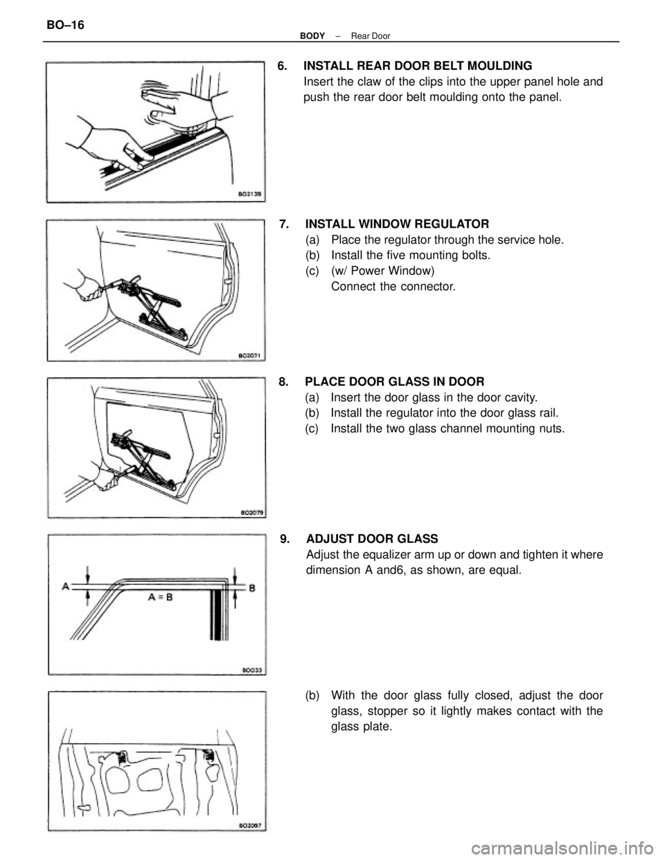
7. INSTALL WINDOW REGULATOR
(a) Place the regulator through the service hole.
(b) Install the five mounting bolts.
(c) (w/ Power Window)
Connect the connector. 6. INSTALL REAR DOOR BELT MOULDING
Insert the claw of the clips into the upper panel hole and
push the rear door belt moulding onto the panel.
8. PLACE DOOR GLASS IN DOOR
(a) Insert the door glass in the door cavity.
(b) Install the regulator into the door glass rail.
(c) Install the two glass channel mounting nuts.
9. ADJUST DOOR GLASS
Adjust the equalizer arm up or down and tighten it where
dimension A and6, as shown, are equal.
(b) With the door glass fully closed, adjust the door
glass, stopper so it lightly makes contact with the
glass plate.
± BODYRear DoorBO±16
Page 683 of 2389
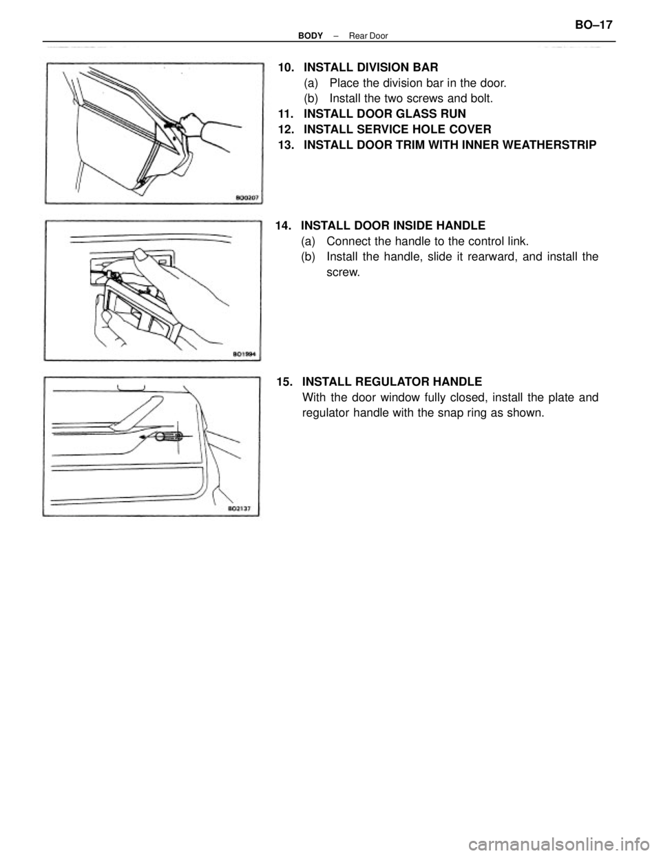
10. INSTALL DIVISION BAR
(a) Place the division bar in the door.
(b) Install the two screws and bolt.
11. INSTALL DOOR GLASS RUN
12. INSTALL SERVICE HOLE COVER
13. INSTALL DOOR TRIM WITH INNER WEATHERSTRIP
14. INSTALL DOOR INSIDE HANDLE
(a) Connect the handle to the control link.
(b) Install the handle, slide it rearward, and install the
screw.
15. INSTALL REGULATOR HANDLE
With the door window fully closed, install the plate and
regulator handle with the snap ring as shown.
± BODYRear DoorBO±17
Page 684 of 2389
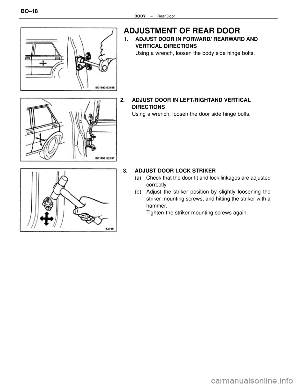
3. ADJUST DOOR LOCK STRIKER
(a) Check that the door fit and lock linkages are adjusted
correctly.
(b) Adjust the striker position by slightly loosening the
striker mounting screws, and hitting the striker with a
hammer.
Tighten the striker mounting screws again.
ADJUSTMENT OF REAR DOOR
1. ADJUST DOOR IN FORWARD/ REARWARD AND
VERTICAL DIRECTIONS
Using a wrench, loosen the body side hinge bolts.
2. ADJUST DOOR IN LEFT/RIGHTAND VERTICAL
DIRECTIONS
Using a wrench, loosen the door side hinge bolts.
± BODYRear DoorBO±18
Page 685 of 2389
LUGGAGE COMPARTMENT LID
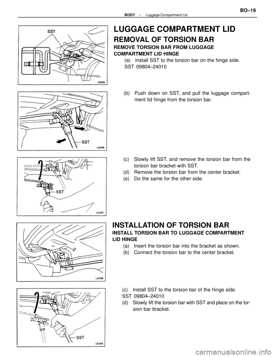
REMOVAL OF TORSION BAR
REMOVE TORSION BAR FROM LUGGAGE
COMPARTMENT LID HINGE
(a) Install SST to the torsion bar on the hinge side.
SST 09804±24010
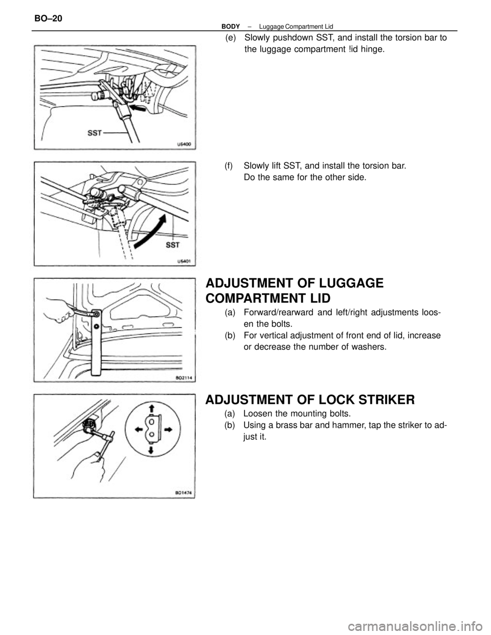
INSTALLATION OF TORSION BAR
INSTALL TORSION BAR TO LUGGAGE COMPARTMENT
LID HINGE
(a) Insert the torsion bar into the bracket as shown.
(b) Connect the torsion bar to the center bracket.(c) Slowly lift SST, and remove the torsion bar from the
torsion bar bracket with SST.
(d) Remove the torsion bar from the center bracket.
(e) Do the same for the other side.
(c) Install SST to the torsion bar of the hinge side.
SST 09804±24010
(d) Slowly lift the torsion bar with SST and place on the tor-
sion bar bracket. (b) Push down on SST, and pull the luggage compart-
ment lid hinge from the torsion bar.
± BODYLuggage Compartment LidBO±19
Page 686 of 2389
ADJUSTMENT OF LUGGAGE
COMPARTMENT LID
(a) Forward/rearward and left/right adjustments loos-
en the bolts.
(b) For vertical adjustment of front end of lid, increase
or decrease the number of washers.
ADJUSTMENT OF LOCK STRIKER
(a) Loosen the mounting bolts.
(b) Using a brass bar and hammer, tap the striker to ad-
just it. (e) Slowly pushdown SST, and install the torsion bar to
the luggage compartment !id hinge.
(f) Slowly lift SST, and install the torsion bar.
Do the same for the other side.
± BODYLuggage Compartment LidBO±20
Page 687 of 2389
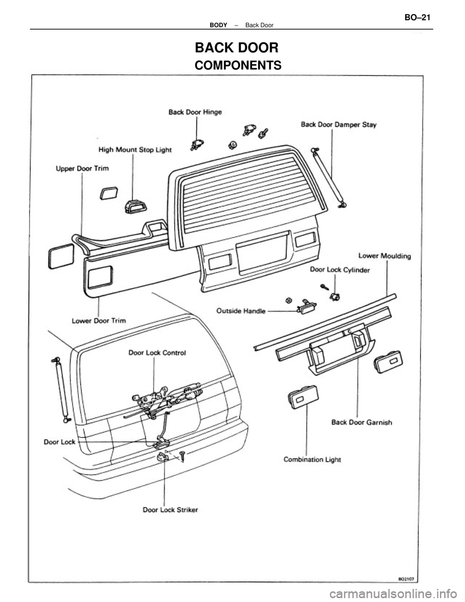
BACK DOOR
COMPONENTS
± BODYBack DoorBO±21
Page 688 of 2389
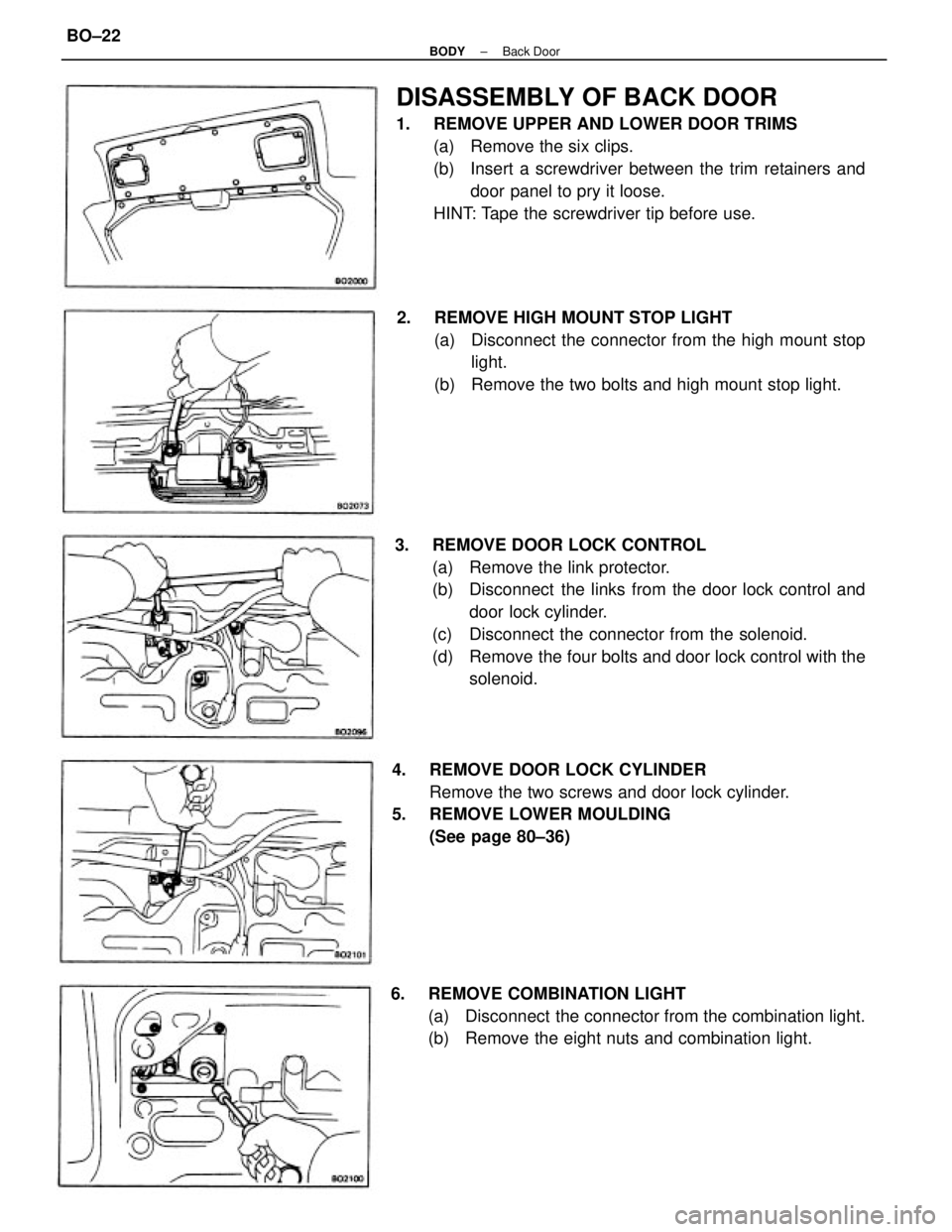
3. REMOVE DOOR LOCK CONTROL
(a) Remove the link protector.
(b) Disconnect the links from the door lock control and
door lock cylinder.
(c) Disconnect the connector from the solenoid.
(d) Remove the four bolts and door lock control with the
solenoid.
DISASSEMBLY OF BACK DOOR
1. REMOVE UPPER AND LOWER DOOR TRIMS
(a) Remove the six clips.
(b) Insert a screwdriver between the trim retainers and
door panel to pry it loose.
HINT: Tape the screwdriver tip before use.
2. REMOVE HIGH MOUNT STOP LIGHT
(a) Disconnect the connector from the high mount stop
light.
(b) Remove the two bolts and high mount stop light.
4. REMOVE DOOR LOCK CYLINDER
Remove the two screws and door lock cylinder.
5. REMOVE LOWER MOULDING
(See page 80±36)
6. REMOVE COMBINATION LIGHT
(a) Disconnect the connector from the combination light.
(b) Remove the eight nuts and combination light.
± BODYBack DoorBO±22
Page 689 of 2389
ASSEMBLY OF BACK DOOR
(See page 80±21)
INSTALL BACK DOOR PARTS BY FOLLOWING
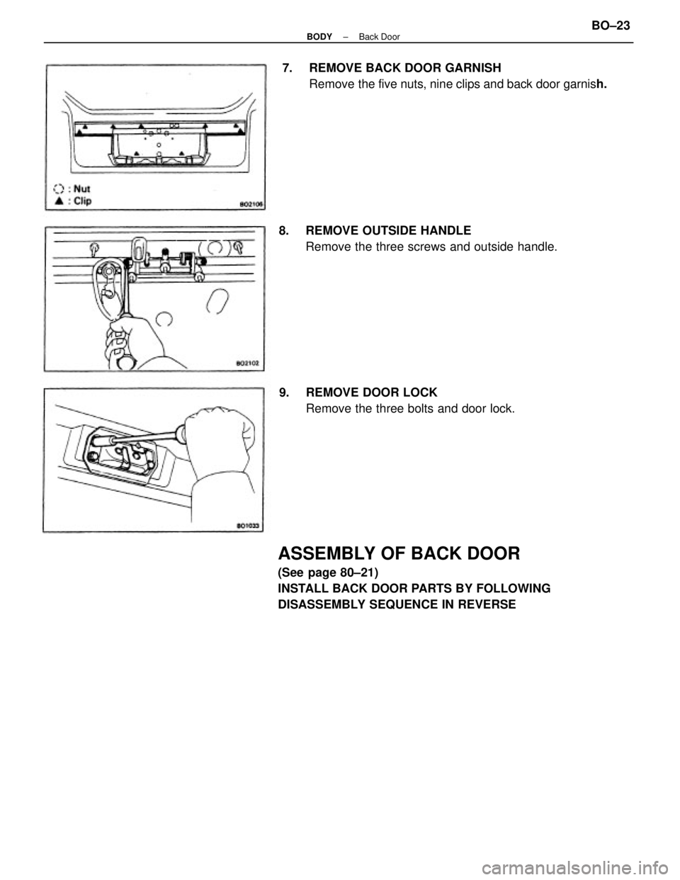
DISASSEMBLY SEQUENCE IN REVERSE7. REMOVE BACK DOOR GARNISH
Remove the five nuts, nine clips and back door garnish.
8. REMOVE OUTSIDE HANDLE
Remove the three screws and outside handle.
9. REMOVE DOOR LOCK
Remove the three bolts and door lock.
± BODYBack DoorBO±23
Page 690 of 2389
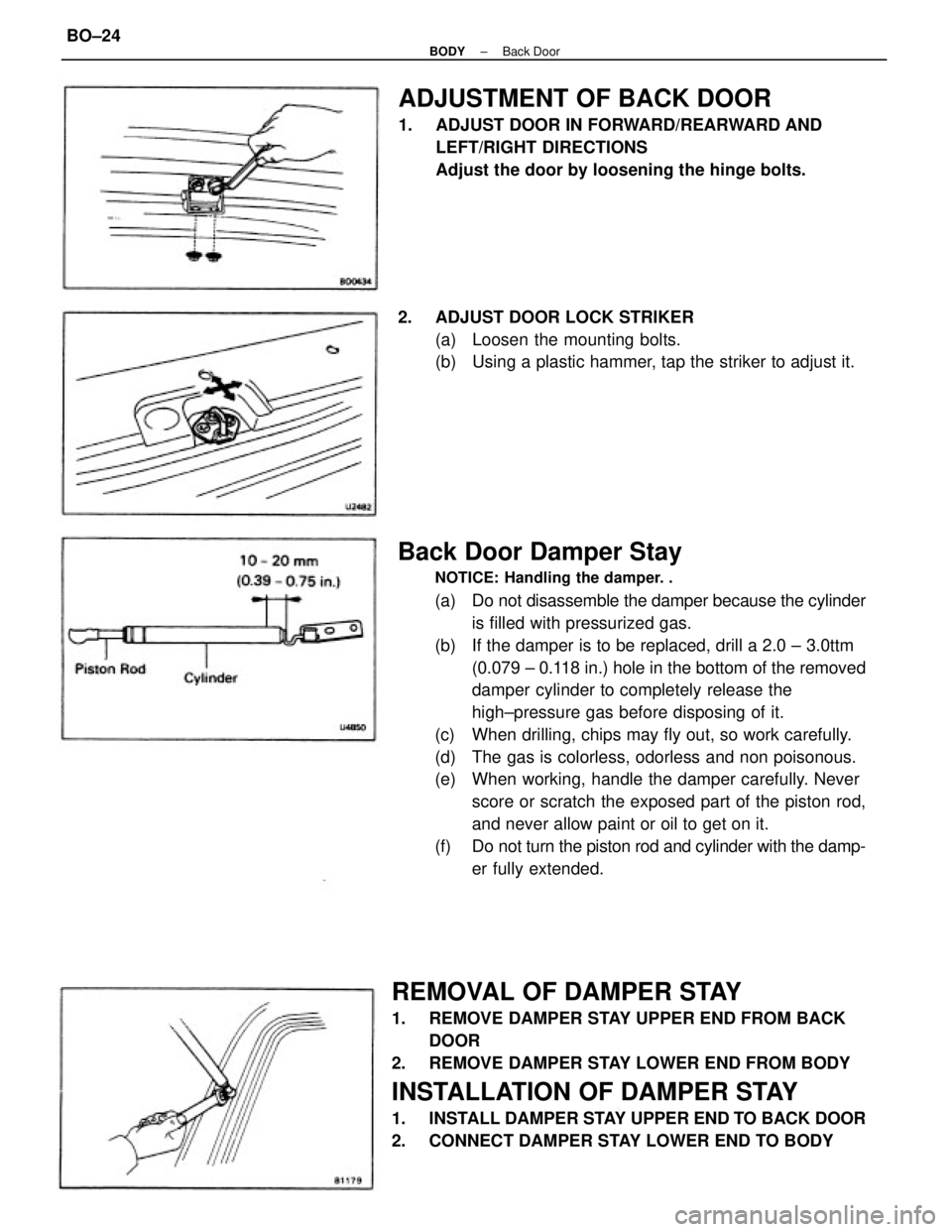
Back Door Damper Stay
NOTICE: Handling the damper. .
(a) Do not disassemble the damper because the cylinder
is filled with pressurized gas.
(b) If the damper is to be replaced, drill a 2.0 ± 3.0ttm
(0.079 ± 0.118 in.) hole in the bottom of the removed
damper cylinder to completely release the
high±pressure gas before disposing of it.
(c) When drilling, chips may fly out, so work carefully.
(d) The gas is colorless, odorless and non poisonous.
(e) When working, handle the damper carefully. Never
score or scratch the exposed part of the piston rod,
and never allow paint or oil to get on it.
(f) Do not turn the piston rod and cylinder with the damp-
er fully extended.
REMOVAL OF DAMPER STAY
1. REMOVE DAMPER STAY UPPER END FROM BACK
DOOR
2. REMOVE DAMPER STAY LOWER END FROM BODY
INSTALLATION OF DAMPER STAY
1. INSTALL DAMPER STAY UPPER END TO BACK DOOR
2. CONNECT DAMPER STAY LOWER END TO BODY
ADJUSTMENT OF BACK DOOR
1. ADJUST DOOR IN FORWARD/REARWARD AND
LEFT/RIGHT DIRECTIONS
Adjust the door by loosening the hinge bolts.
2. ADJUST DOOR LOCK STRIKER
(a) Loosen the mounting bolts.
(b) Using a plastic hammer, tap the striker to adjust it.
± BODYBack DoorBO±24
Trending: fuel, battery replacement, oil capacity, key, fuse diagram, parking brake, height adjustment
