TOYOTA CAMRY V20 1986 Service Information
CAMRY V20 1986
TOYOTA
TOYOTA
https://www.carmanualsonline.info/img/14/57449/w960_57449-0.png
TOYOTA CAMRY V20 1986 Service Information
Trending: battery capacity, service schedule, fuel tank capacity, bulb, oil pressure, inflation pressure, automatic transmission
Page 751 of 2389
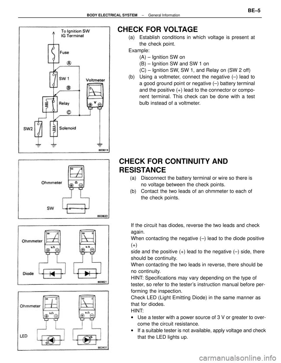
If the circuit has diodes, reverse the two leads and check
again.
When contacting the negative (±) lead to the diode positive
(+)
side and the positive (+) lead to the negative (±) side, there
should be continuity.
When contacting the two leads in reverse, there should be
no continuity.
HINT: Specifications may vary depending on the type of
tester, so refer to the tester's instruction manual before per-
forming the inspection.
Check LED (Light Emitting Diode) in the same manner as
that for diodes.
HINT:
wUse a tester with a power source of 3 V or greater to over-
come the circuit resistance.
wIf a suitable tester is not available, apply voltage and check
that the LED lights up.
CHECK FOR VOLTAGE
(a) Establish conditions in which voltage is present at
the check point.
Example:
(A) ± Ignition SW on
(B) ± Ignition SW and SW 1 on
(C) ± Ignition SW, SW 1, and Relay on (SW 2 off)
(b) Using a voltmeter, connect the negative (±) lead to
a good ground point or negative (±) battery terminal
and the positive (+) lead to the connector or compo-
nent terminal. This check can be done with a test
bulb instead of a voltmeter.
CHECK FOR CONTINUITY AND
RESISTANCE
(a) Disconnect the battery terminal or wire so there is
no voltage between the check points.
(b) Contact the two leads of an ohmmeter to each of
the check points.
± BODY ELECTRICAL SYSTEMGeneral InformationBE±5
Page 752 of 2389
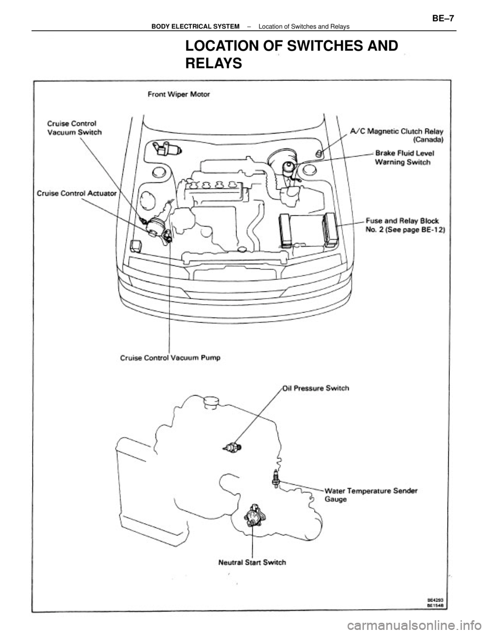
CHECK FOR SHORT CIRCUIT
(a) Remove the blown fuse and eliminate all toads from
the fuse.
(b) Connect a test bulb in place of the fuse.
(e) Establish conditions in which the test bulb comes on.
Example:
(A) ± Ignition SW on
(B) ± Ignition SW and SW 1 on
(C) ± Ignition SW, SW 1 and Relay on (Connect the
Relay) and SW 2 oft (or Disconnect SW 2)
(d) Disconnect and reconnect the connectors while
watching the test bulb.
The short lies between the connector where the test
bulb stays lit and the connector where the bulb goes
out.
(e) Find the exact location of the short by lightly shaking
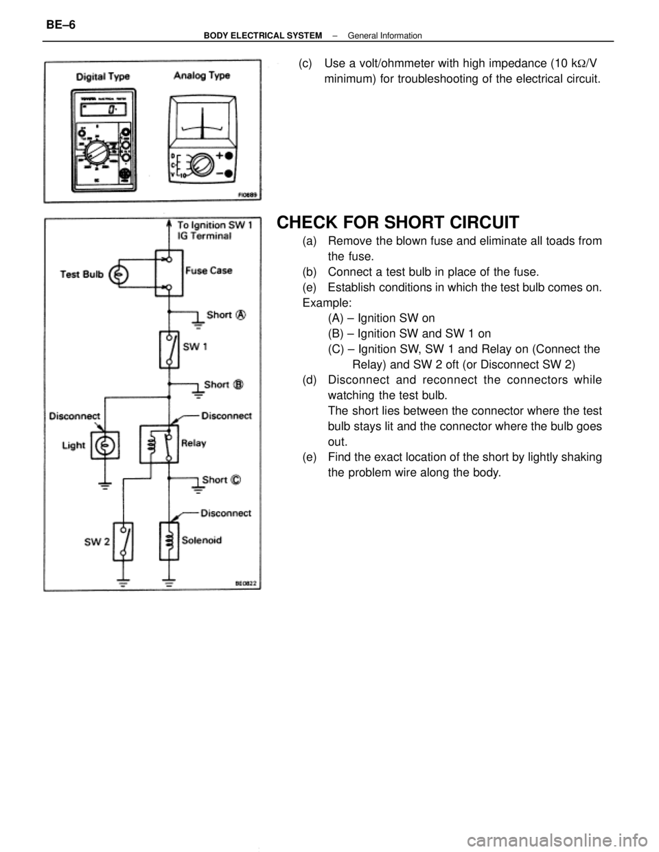
the problem wire along the body. (c) Use a volt/ohmmeter with high impedance (10 k
�/V
minimum) for troubleshooting of the electrical circuit.
± BODY ELECTRICAL SYSTEMGeneral InformationBE±6
Page 753 of 2389
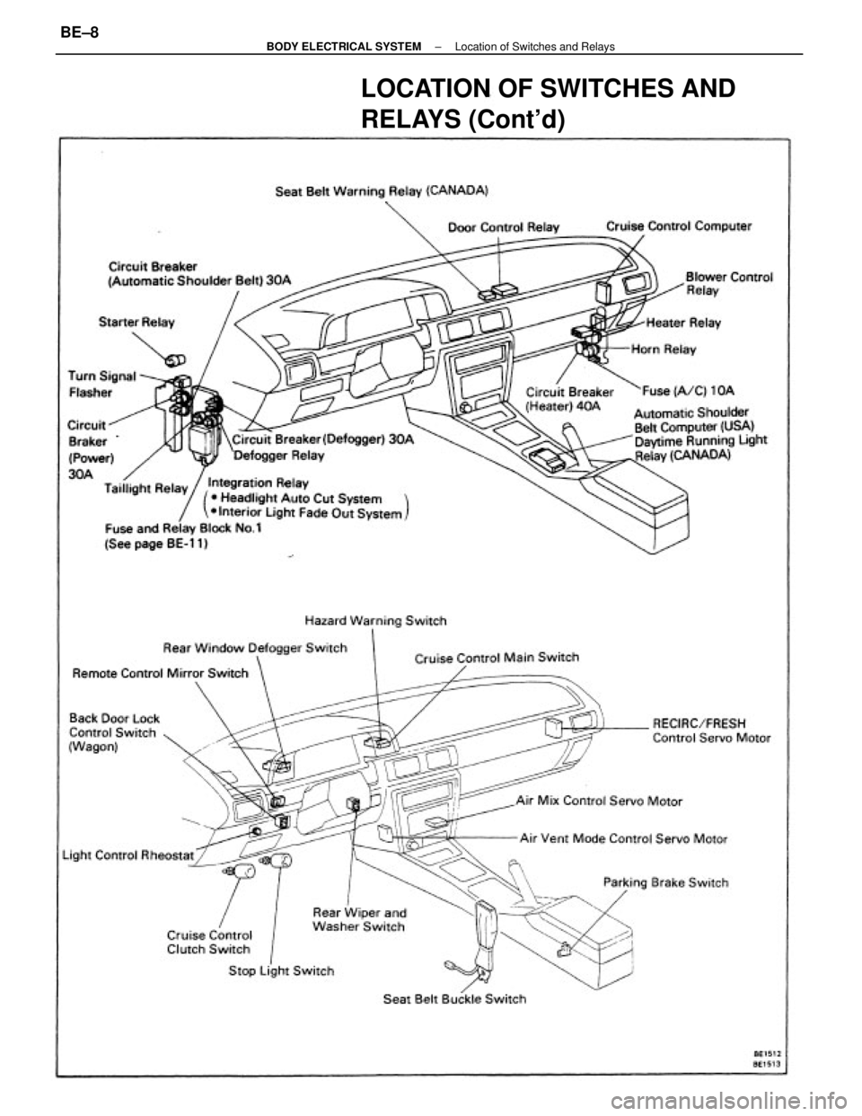
LOCATION OF SWITCHES AND
RELAYS
± BODY ELECTRICAL SYSTEMLocation of Switches and RelaysBE±7
Page 754 of 2389
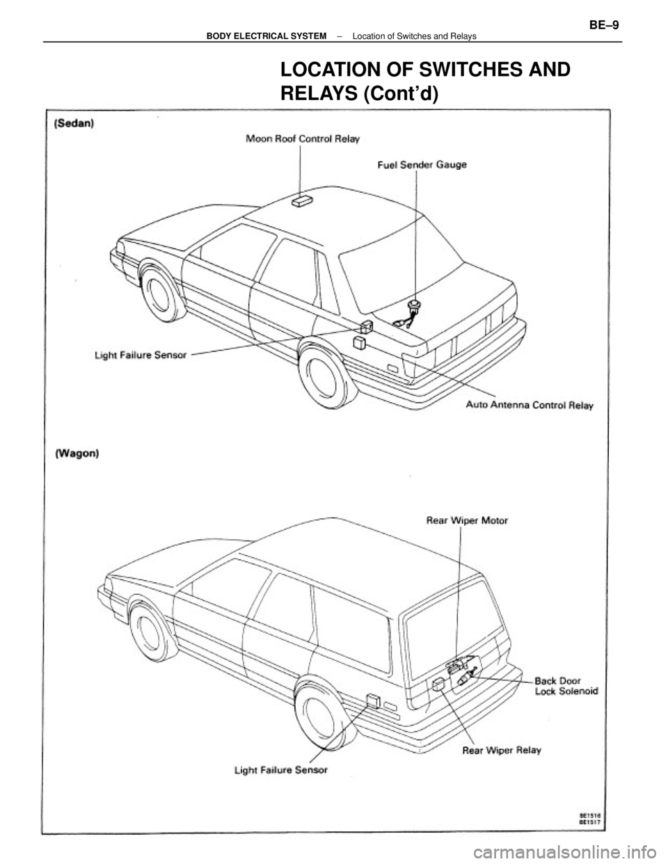
LOCATION OF SWITCHES AND
RELAYS (Cont'd)
± BODY ELECTRICAL SYSTEMLocation of Switches and RelaysBE±8
Page 755 of 2389
LOCATION OF SWITCHES AND
RELAYS (Cont'd)
± BODY ELECTRICAL SYSTEMLocation of Switches and RelaysBE±9
Page 756 of 2389
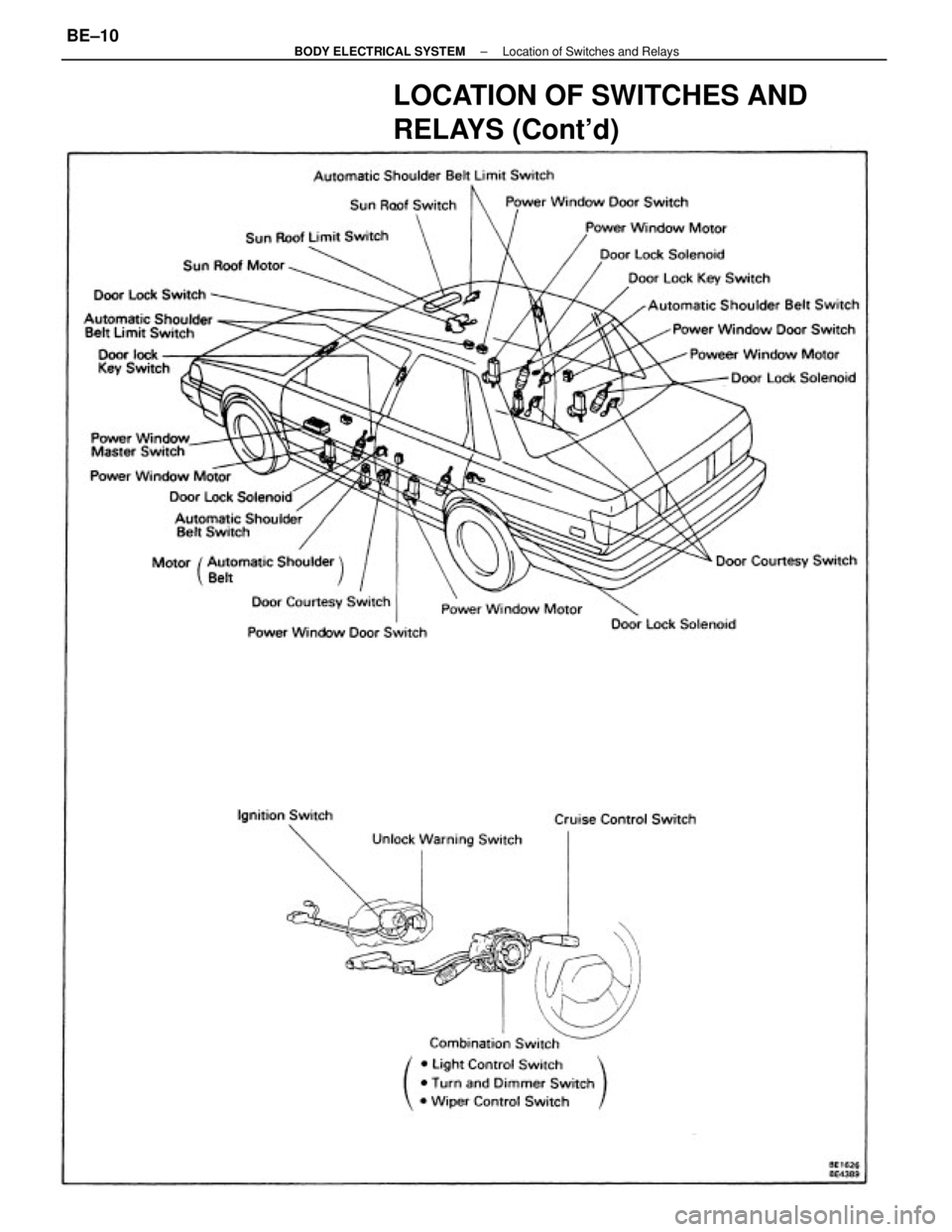
LOCATION OF SWITCHES AND
RELAYS (Cont'd)
± BODY ELECTRICAL SYSTEMLocation of Switches and RelaysBE±10
Page 757 of 2389
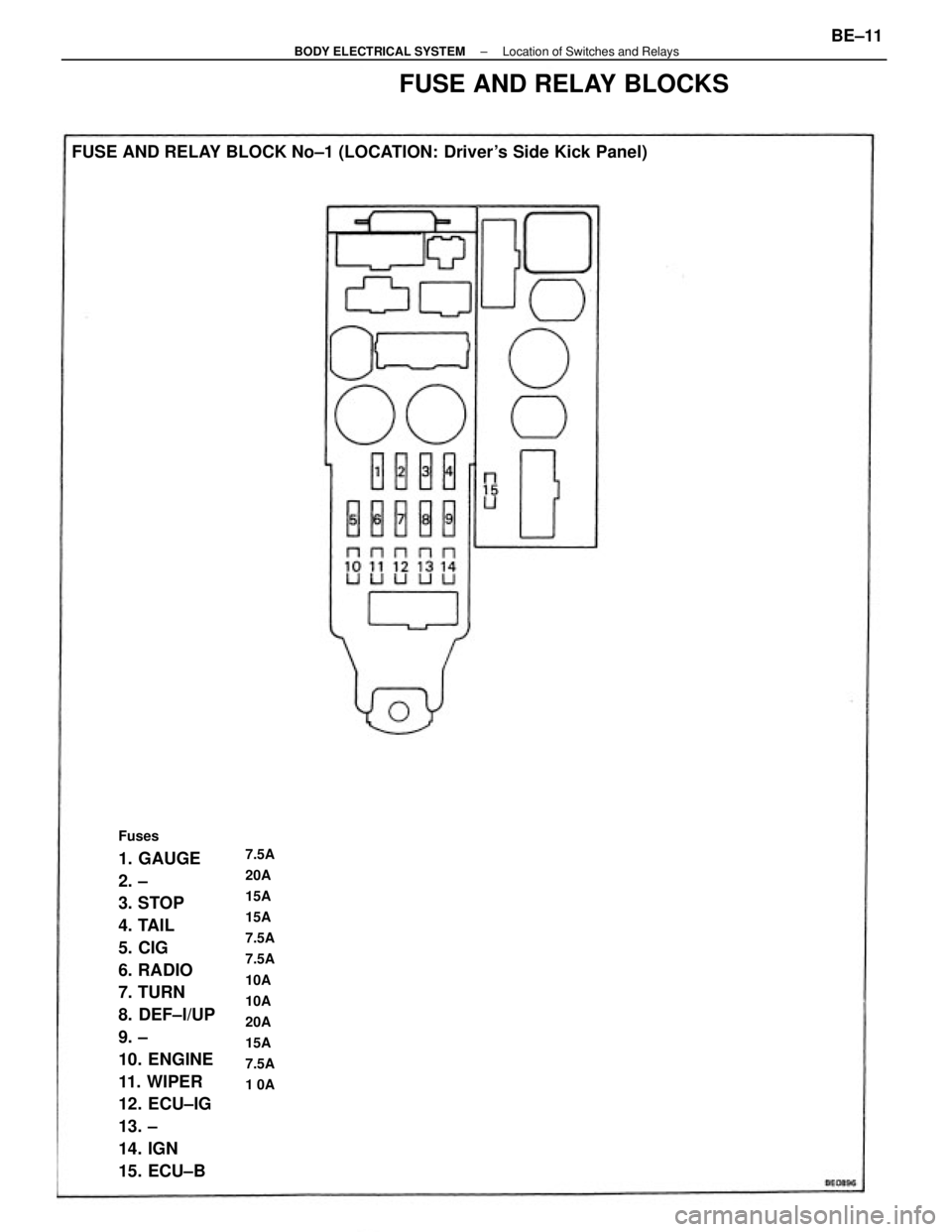
Fuses
1. GAUGE
2. ±
3. STOP
4. TAIL
5. CIG
6. RADIO
7. TURN
8. DEF±I/UP
9. ±
10. ENGINE
11. WIPER
12. ECU±IG
13. ±
14. IGN
15. ECU±B FUSE AND RELAY BLOCK No±1 (LOCATION: Driver's Side Kick Panel)7.5A
20A
15A
15A
7.5A
7.5A
10A
10A
20A
15A
7.5A
1 0A
FUSE AND RELAY BLOCKS
± BODY ELECTRICAL SYSTEMLocation of Switches and RelaysBE±11
Page 758 of 2389
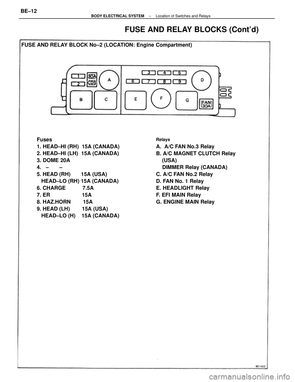
Fuses
1. HEAD±HI (RH) 15A (CANADA)
2. HEAD±HI (LH) 15A (CANADA)
3. DOME 20A
4. ± ±
5. HEAD (RH) 15A (USA)
HEAD±LO (RH) 15A (CANADA)
6. CHARGE 7.5A
7. ER 15A
8. HAZ.HORN 15A
9. HEAD (LH) 15A (USA)
HEAD±LO (H) 15A (CANADA)Relays
A. A/C FAN No.3 Relay
B. A/C MAGNET CLUTCH Relay
(USA)
DIMMER Relay (CANADA)
C. A/C FAN No.2 Relay
D. FAN No. 1 Relay
E. HEADLIGHT Relay
F. EFI MAIN Relay
G. ENGINE MAIN Relay FUSE AND RELAY BLOCK No±2 (LOCATION: Engine Compartment)
FUSE AND RELAY BLOCKS (Cont'd)
± BODY ELECTRICAL SYSTEMLocation of Switches and RelaysBE±12
Page 759 of 2389
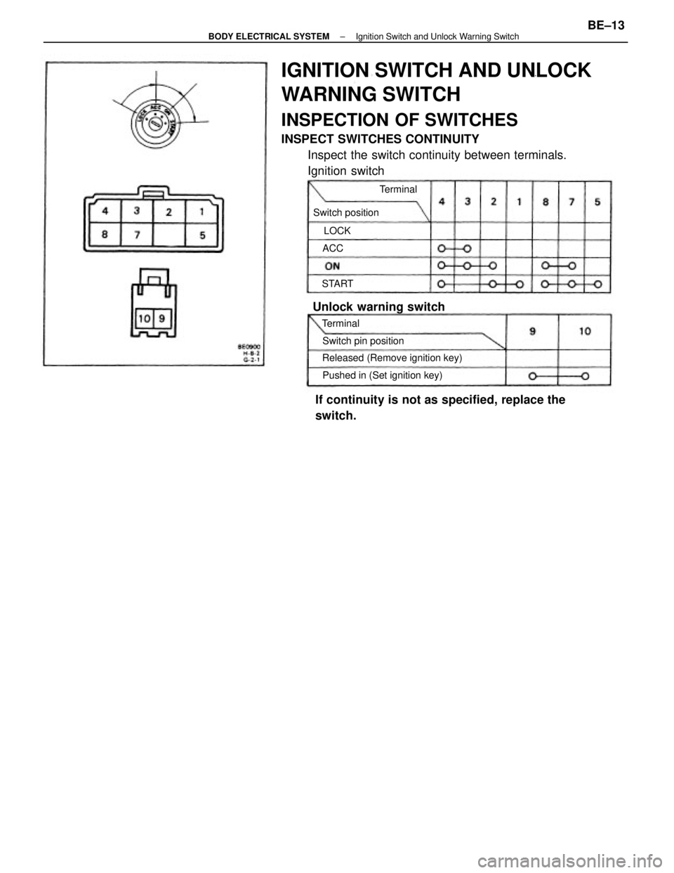
IGNITION SWITCH AND UNLOCK
WARNING SWITCH
INSPECTION OF SWITCHES
INSPECT SWITCHES CONTINUITY
Inspect the switch continuity between terminals.
Ignition switch
If continuity is not as specified, replace the
switch.
Released (Remove ignition key)
Pushed in (Set ignition key)
Unlock warning switch
Switch pin position Switch positionTerminal
Terminal STARTLOCK
ACC
± BODY ELECTRICAL SYSTEMIgnition Switch and Unlock Warning SwitchBE±13
Page 760 of 2389
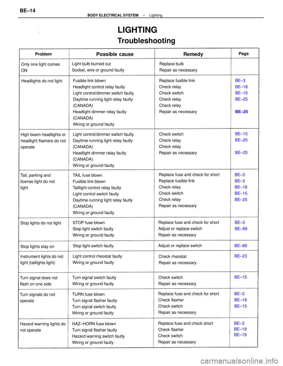
Fusible link blown
Headlight control relay faulty
Light control/dimmer switch faulty
Daytime running light relay faulty
(CANADA)
Headlight dimmer relay faulty
(CANADA)
Wiring or ground faulty
Replace fuse and check for short
Replace fusible fink
Check relay
Check switch
Check relay
Repair as necessary TAIL fuse blown
Fusible link blown
Taillight control relay faulty
Light control switch faulty
Daytime running light relay faulty
(CANADA)
Wiring or ground faulty Light control/dimmer switch faulty
Daytime running light relay faulty
(CANADA)
Headlight dimmer relay faulty
(CANADA)
Wiring or ground faultyReplace fusible link
Check relay
Check switch
Check relay
Check relay
Repair as necessary
Replace fuse and check for short
Check flasher
Check switch
Repair as necessary
Replace fuse and check short
Check flasher
Check switch
Repair as necessary HAZ±HORN fuse blown
Turn signal flasher faulty
Hazard warning switch faulty
Wiring or ground faultyCheck switch
Check relay
Check relay
Repair as necessary
Replace fuse and check for short
Adjust or replace switch
Repair as necessary
TURN fuse blown
Turn signal flasher faulty
Turn signal switch faulty
Wiring or ground faulty
LIGHTING
Troubleshooting
STOP fuse blown
Stop light swtich faulty
Wiring or ground faulty Light bulb burned out
Socket, wire or ground faulty
High beam headlights or
headlight flashers do not
operate
Light control rheostat faulty
Wiring or ground faulty Instrument lights do not
light (taillights light)Tail, parking and
license light do not
light
Turn signal switch faulty
Wiring or ground faulty
Hazard warning lights do
not operateReplace bulb
Repair as necessary
Headlights do not light
Check switch
Repair as necessaryCheck rheostat
Repair as necessary Only one light comes
ON
Turn signal does not
flash on one side
Turn signals do not
operateBE±3
BE±3
BE±18
BE±15
BE±25
Adjust or replace switch
Stop light switch faultyBE±3
BE±18
BE±15
BE±25
Stop lights do not light
Stop lights stay on
BE±3
BE±19
BE±19BE±3
BE±19
BE±15
Possible cause
BE±15
BE±25
BE±3
BE±89
RemedyProblem
BE±15BE±23 BE±89BE±25
BE±25Page
± BODY ELECTRICAL SYSTEMLightingBE±14
Trending: gas type, oil change, air conditioning, headlight aiming, ECU, fuse chart, high beam

