TOYOTA CAMRY V20 1986 Service Information
CAMRY V20 1986
TOYOTA
TOYOTA
https://www.carmanualsonline.info/img/14/57449/w960_57449-0.png
TOYOTA CAMRY V20 1986 Service Information
Trending: recommended oil, Air, radiator cap, battery capacity, check engine light, brake pads, ECO mode
Page 741 of 2389
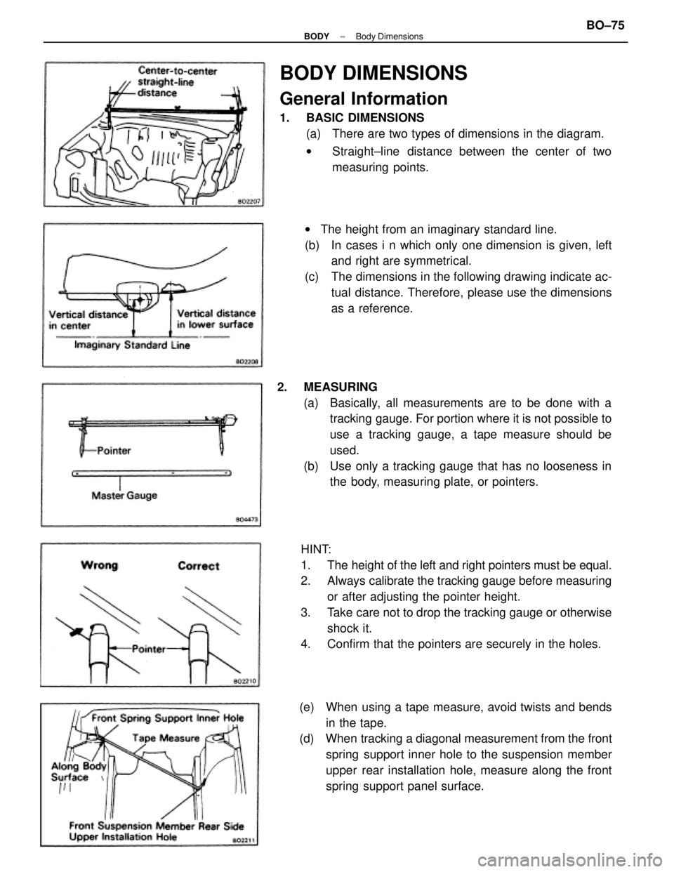
BODY DIMENSIONS
General Information
1. BASIC DIMENSIONS
(a) There are two types of dimensions in the diagram.
wStraight±line distance between the center of two
measuring points.
HINT:
1. The height of the left and right pointers must be equal.
2. Always calibrate the tracking gauge before measuring
or after adjusting the pointer height.
3. Take care not to drop the tracking gauge or otherwise
shock it.
4. Confirm that the pointers are securely in the holes. 2. MEASURING
(a) Basically, all measurements are to be done with a
tracking gauge. For portion where it is not possible to
use a tracking gauge, a tape measure should be
used.
(b) Use only a tracking gauge that has no looseness in
the body, measuring plate, or pointers. wThe height from an imaginary standard line.
(b) In cases i n which only one dimension is given, left
and right are symmetrical.
(c) The dimensions in the following drawing indicate ac-
tual distance. Therefore, please use the dimensions
as a reference.
(e) When using a tape measure, avoid twists and bends
in the tape.
(d) When tracking a diagonal measurement from the front
spring support inner hole to the suspension member
upper rear installation hole, measure along the front
spring support panel surface.
± BODYBody DimensionsBO±75
Page 742 of 2389
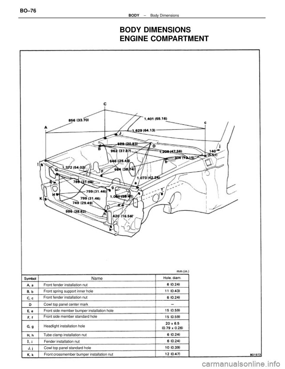
BODY DIMENSIONS
ENGINE COMPARTMENT
Front crossmember bumper installation nut Front side member bumper installation hole
Front side member standard hole Front spring support inner hole
Cowl top panel standard hole Cowl top panel center mark
Tube clamp installation nut Front fender installation nut
Headlight installation hole Front fender installation nut
Fender installation nut
Name
± BODYBody DimensionsBO±76
Page 743 of 2389
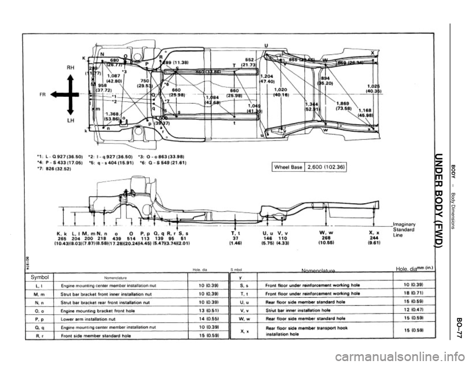
UNDER BODY (FWD)
Nomenclature
Nomenclature
Hole. dia
Hole. dia
Symbol
S mbol
± BODYBody DimensionsBO±77
Page 744 of 2389
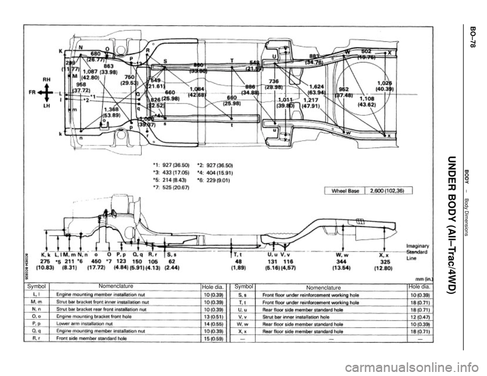
UNDER BODY (All±Trac/4WD)
Nomenclature Nomenclature
Hole dia.
Hole dia.Symbol Symbol
± BODYBody DimensionsBO±78
Page 745 of 2389
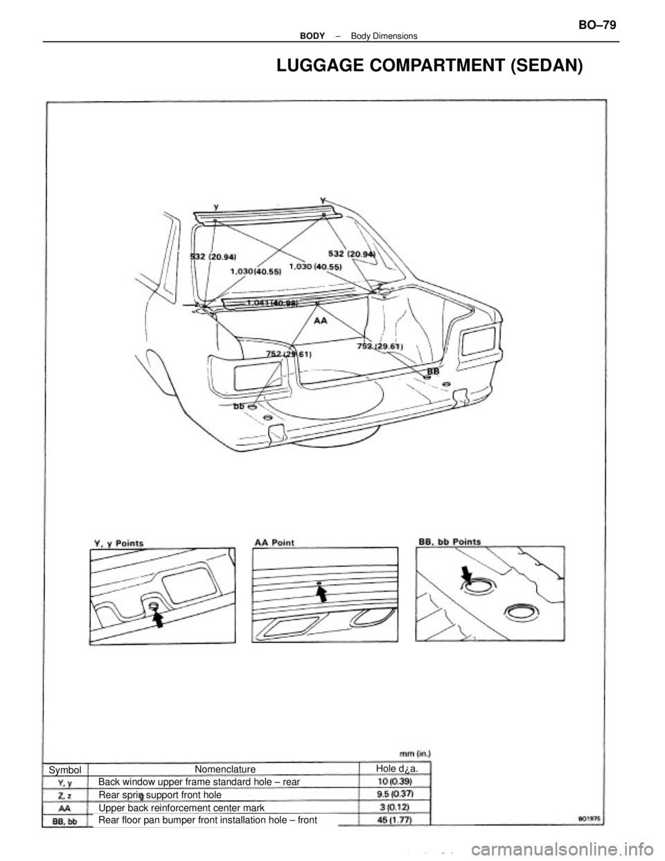
LUGGAGE COMPARTMENT (SEDAN)
Rear floor pan bumper front installation hole ± front Back window upper frame standard hole ± rear
Upper back reinforcement center mark Rear sprin support front holeNomenclatureHole d¿a.
Symbol
± BODYBody DimensionsBO±79
Page 746 of 2389
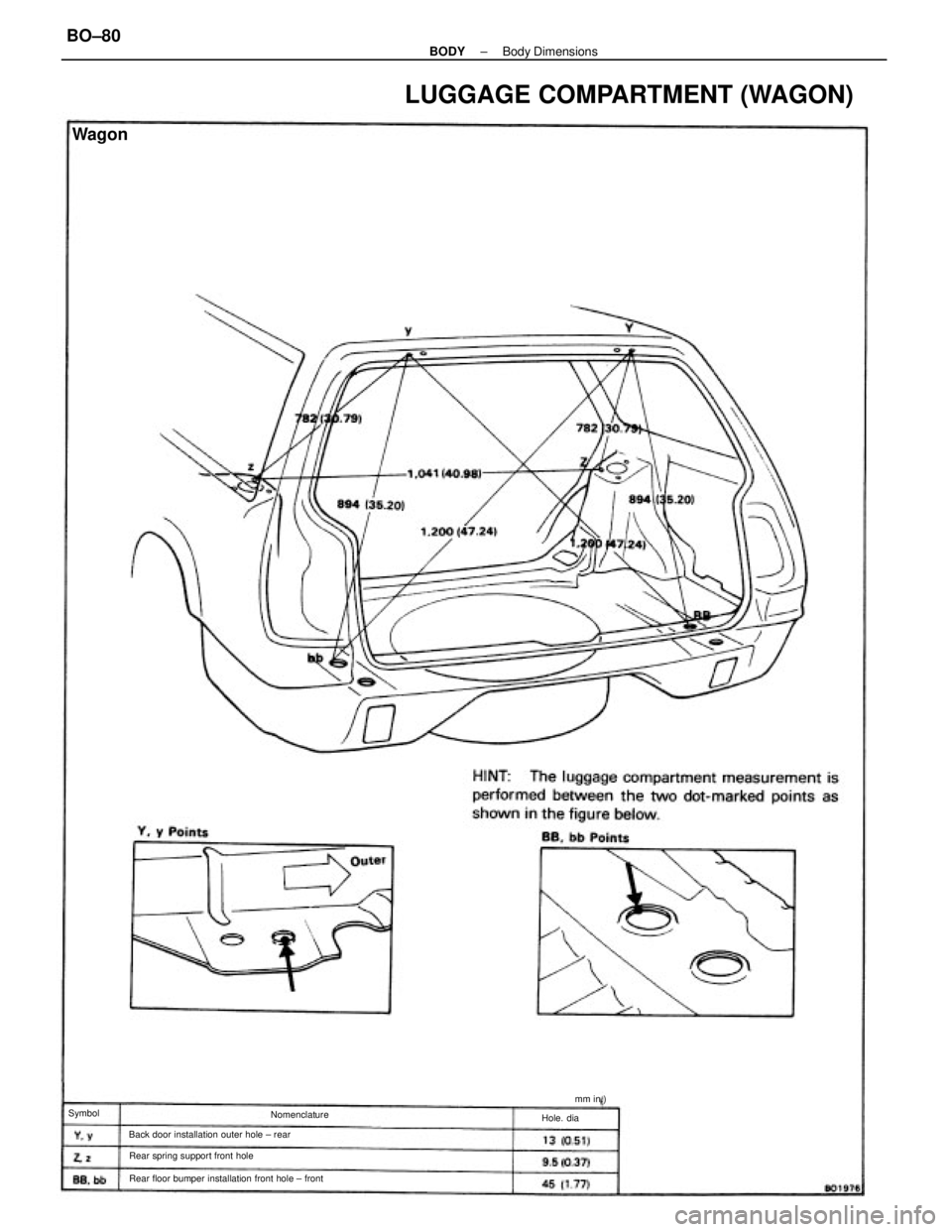
LUGGAGE COMPARTMENT (WAGON)
Rear floor bumper installation front hole ± front Back door installation outer hole ± rear
Rear spring support front hole
Wagon
Nomenclature
Hole. dia Symbolmm in.)
± BODYBody DimensionsBO±80
Page 747 of 2389
BODY ELECTRICAL SYSTEM
± BODY ELECTRICAL SYSTEMBE±1
Page 748 of 2389
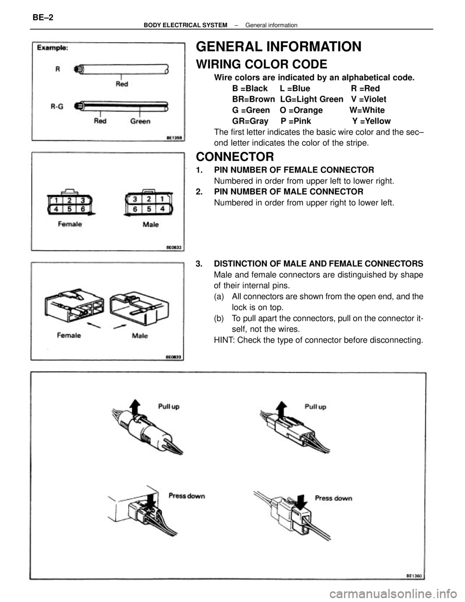
GENERAL INFORMATION
WIRING COLOR CODE
Wire colors are indicated by an alphabetical code.
B =Black L =Blue R =Red
BR=Brown LG=Light Green V =Violet
G =Green O =Orange W=White
GR=Gray P =Pink Y =Yellow
The first letter indicates the basic wire color and the sec±
ond letter indicates the color of the stripe.
CONNECTOR
1. PIN NUMBER OF FEMALE CONNECTOR
Numbered in order from upper left to lower right.
2. PIN NUMBER OF MALE CONNECTOR
Numbered in order from upper right to lower left.
3. DISTINCTION OF MALE AND FEMALE CONNECTORS
Male and female connectors are distinguished by shape
of their internal pins.
(a) All connectors are shown from the open end, and the
lock is on top.
(b) To pull apart the connectors, pull on the connector it-
self, not the wires.
HINT: Check the type of connector before disconnecting.
± BODY ELECTRICAL SYSTEMGeneral informationBE±2
Page 749 of 2389
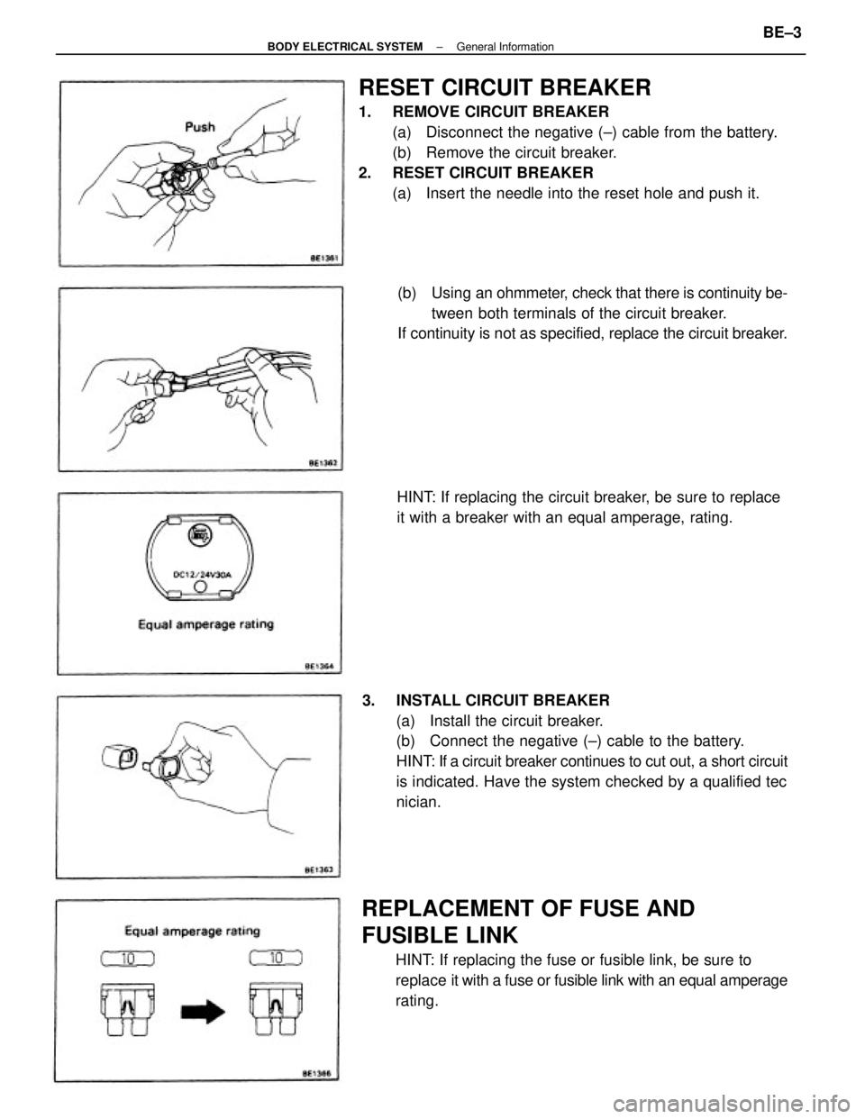
RESET CIRCUIT BREAKER
1. REMOVE CIRCUIT BREAKER
(a) Disconnect the negative (±) cable from the battery.
(b) Remove the circuit breaker.
2. RESET CIRCUIT BREAKER
(a) Insert the needle into the reset hole and push it.
3. INSTALL CIRCUIT BREAKER
(a) Install the circuit breaker.
(b) Connect the negative (±) cable to the battery.
HINT: If a circuit breaker continues to cut out, a short circuit
is indicated. Have the system checked by a qualified tec
nician.
REPLACEMENT OF FUSE AND
FUSIBLE LINK
HINT: If replacing the fuse or fusible link, be sure to
replace it with a fuse or fusible link with an equal amperage
rating.(b) Using an ohmmeter, check that there is continuity be-
tween both terminals of the circuit breaker.
If continuity is not as specified, replace the circuit breaker.
HINT: If replacing the circuit breaker, be sure to replace
it with a breaker with an equal amperage, rating.
± BODY ELECTRICAL SYSTEMGeneral InformationBE±3
Page 750 of 2389
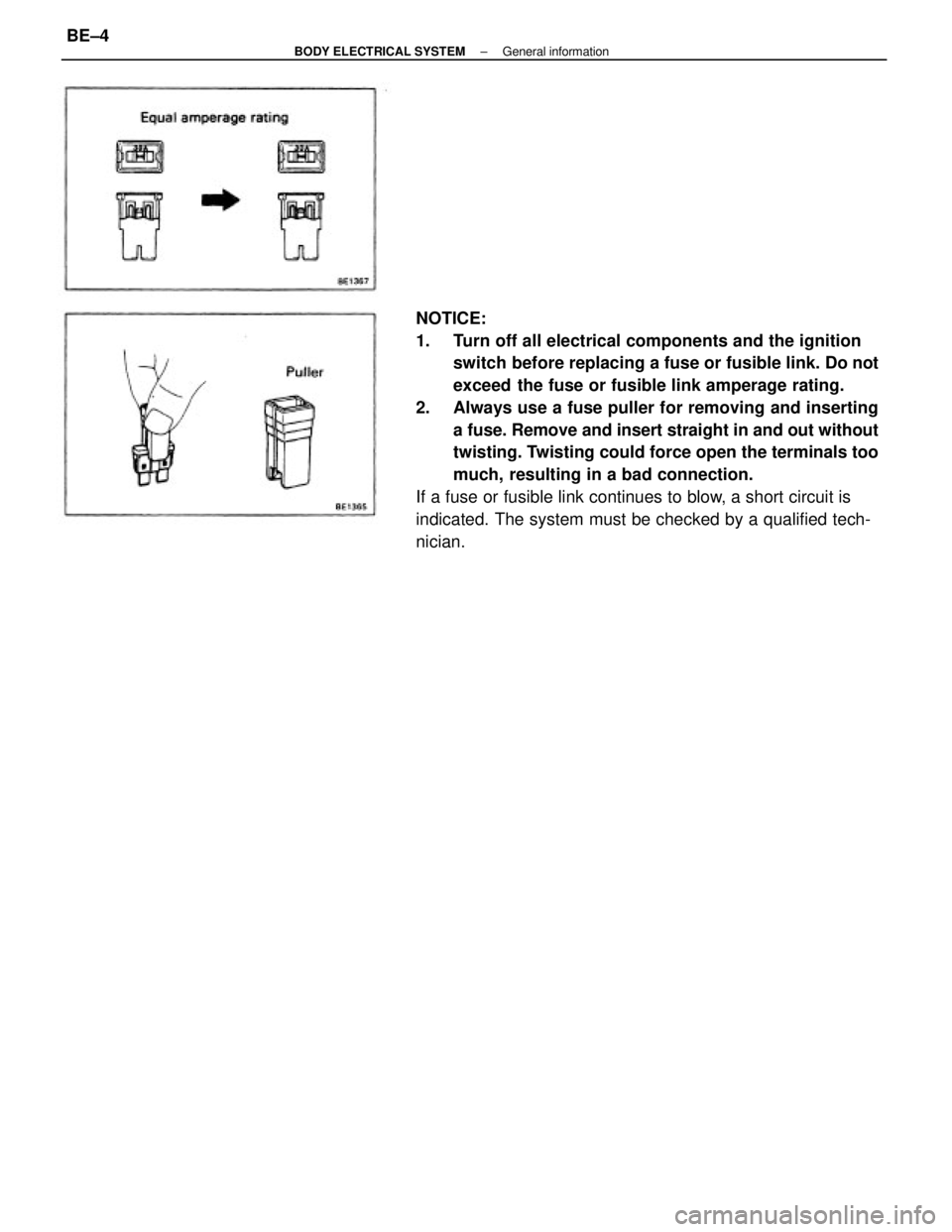
NOTICE:
1. Turn off all electrical components and the ignition
switch before replacing a fuse or fusible link. Do not
exceed the fuse or fusible link amperage rating.
2. Always use a fuse puller for removing and inserting
a fuse. Remove and insert straight in and out without
twisting. Twisting could force open the terminals too
much, resulting in a bad connection.
If a fuse or fusible link continues to blow, a short circuit is
indicated. The system must be checked by a qualified tech-
nician.
± BODY ELECTRICAL SYSTEMGeneral informationBE±4
Trending: wheel bolt torque, lights, instrument panel, change time, relay, flat tire, fuel tank capacity

