TOYOTA CAMRY V20 1986 Service Information
Manufacturer: TOYOTA, Model Year: 1986, Model line: CAMRY V20, Model: TOYOTA CAMRY V20 1986Pages: 2389, PDF Size: 84.44 MB
Page 771 of 2389
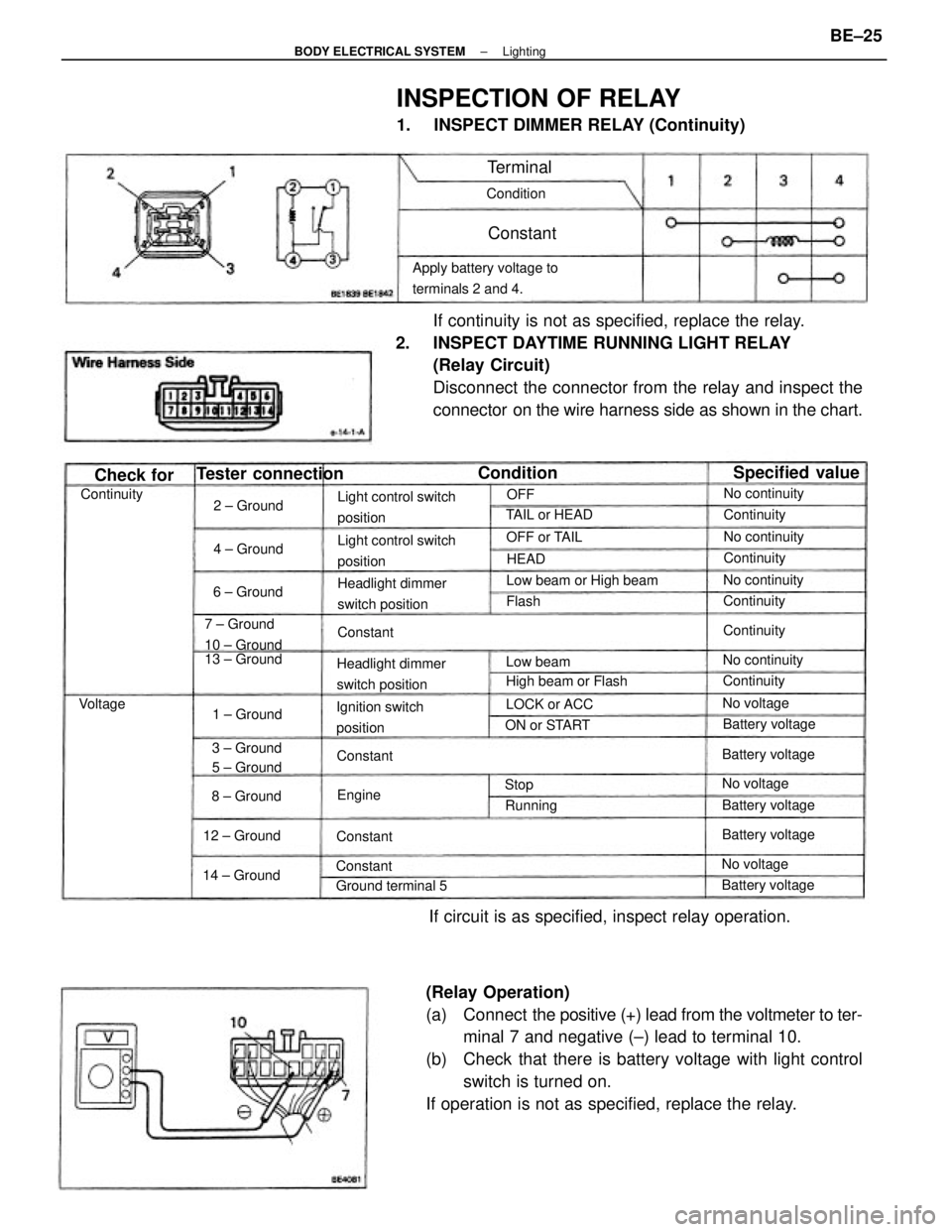
(Relay Operation)
(a) Connect the positive (+) lead from the voltmeter to ter-
minal 7 and negative (±) lead to terminal 10.
(b) Check that there is battery voltage with light control
switch is turned on.
If operation is not as specified, replace the relay.If continuity is not as specified, replace the relay.
2. INSPECT DAYTIME RUNNING LIGHT RELAY
(Relay Circuit)
Disconnect the connector from the relay and inspect the
connector on the wire harness side as shown in the chart.
INSPECTION OF RELAY
1. INSPECT DIMMER RELAY (Continuity)
If circuit is as specified, inspect relay operation.
Apply battery voltage to
terminals 2 and 4.
Light control switch
position
Light control switch
position
Headlight dimmer
switch positionHeadlight dimmer
switch positionLow beam or High beam
Ignition switch
position 7 ± Ground
10 ± Ground
High beam or Flash 13 ± Ground
3 ± Ground
5 ± Ground
Tester connection
Ground terminal 5
Specified value
Battery voltageBattery voltageBattery voltage
Battery voltage Battery voltageNo continuity
No continuity TAIL or HEADNo continuity
No continuity
14 ± Ground12 ± GroundON or STARTLOCK or ACC
1 ± GroundOFF or TAIL
8 ± Ground2 ± Ground
6 ± Ground4 ± Ground
No voltage
No voltage
No voltageContinuity
Continuity Continuity
Continuity
ContinuityContinuity
Condition
Check for
Low beam Condition
Running
Terminal
Constant
Constant
Constant
Constant
Constant Voltage
EngineHEAD
Flash
StopOFF
± BODY ELECTRICAL SYSTEMLightingBE±25
Page 772 of 2389
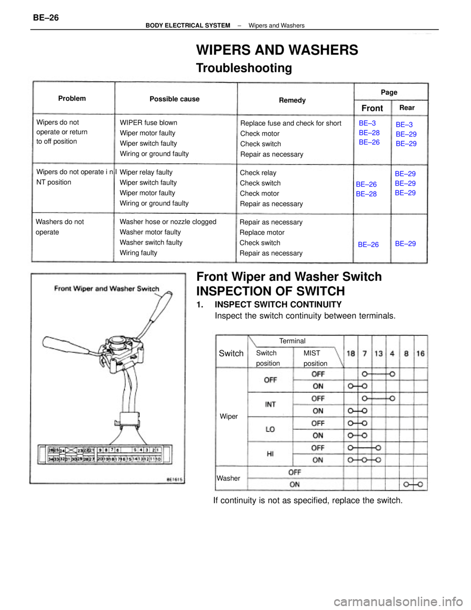
Front Wiper and Washer Switch
INSPECTION OF SWITCH
1. INSPECT SWITCH CONTINUITY
Inspect the switch continuity between terminals.
WIPERS AND WASHERS
Troubleshooting
Replace fuse and check for short
Check motor
Check switch
Repair as necessary
Washer hose or nozzle clogged
Washer motor faulty
Washer switch faulty
Wiring faultyWIPER fuse blown
Wiper motor faulty
Wiper switch faulty
Wiring or ground faulty
Wiper relay faulty
Wiper switch faulty
Wiper motor faulty
Wiring or ground faulty
Repair as necessary
Replace motor
Check switch
Repair as necessaryCheck relay
Check switch
Check motor
Repair as necessary
If continuity is not as specified, replace the switch.
Wipers do not
operate or return
to off position
Wipers do not operate i n I
NT position
Washers do not
operateBE±29
BE±29
BE±29BE±3
BE±29
BE±29 BE±3
BE±28
BE±26 Possible cause
BE±26
BE±28
Switch
positionMIST
position Terminal Remedy Problem
Washer
Switch
WiperBE±26BE±29 Page
FrontRear
± BODY ELECTRICAL SYSTEMWipers and WashersBE±26
Page 773 of 2389
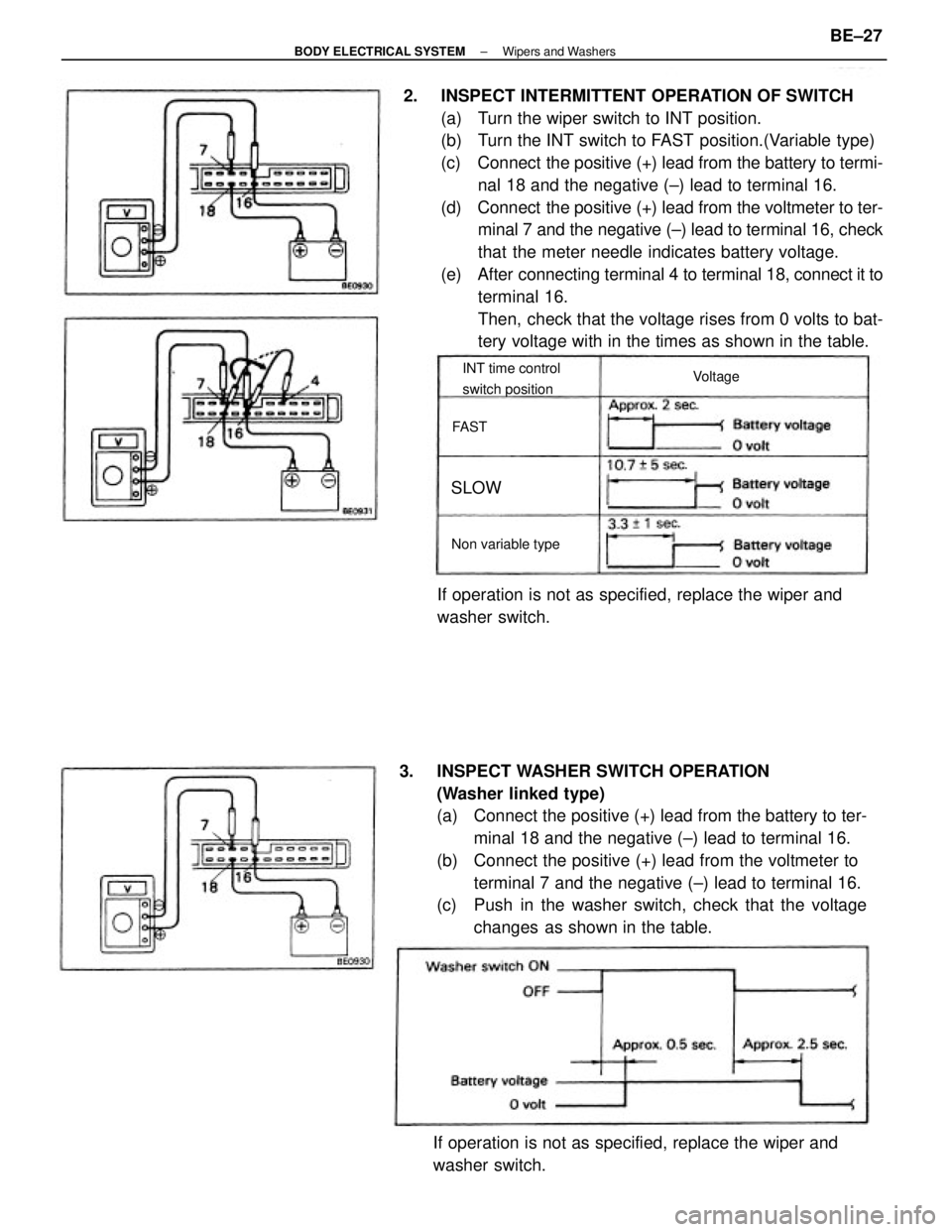
2. INSPECT INTERMITTENT OPERATION OF SWITCH
(a) Turn the wiper switch to INT position.
(b) Turn the INT switch to FAST position.(Variable type)
(c) Connect the positive (+) lead from the battery to termi-
nal 18 and the negative (±) lead to terminal 16.
(d) Connect the positive (+) lead from the voltmeter to ter-
minal 7 and the negative (±) lead to terminal 16, check
that the meter needle indicates battery voltage.
(e) After connecting terminal 4 to terminal 18, connect it to
terminal 16.
Then, check that the voltage rises from 0 volts to bat-
tery voltage with in the times as shown in the table.
3. INSPECT WASHER SWITCH OPERATION
(Washer linked type)
(a) Connect the positive (+) lead from the battery to ter-
minal 18 and the negative (±) lead to terminal 16.
(b) Connect the positive (+) lead from the voltmeter to
terminal 7 and the negative (±) lead to terminal 16.
(c) Push in the washer switch, check that the voltage
changes as shown in the table.
If operation is not as specified, replace the wiper and
washer switch.If operation is not as specified, replace the wiper and
washer switch.
INT time control
switch position
Non variable typeVoltage
SLOW
FAST
± BODY ELECTRICAL SYSTEMWipers and WashersBE±27
Page 774 of 2389
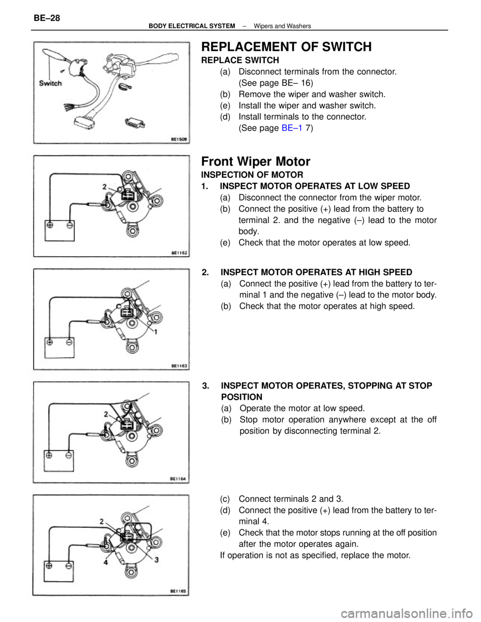
Front Wiper Motor
INSPECTION OF MOTOR
1. INSPECT MOTOR OPERATES AT LOW SPEED
(a) Disconnect the connector from the wiper motor.
(b) Connect the positive (+) lead from the battery to
terminal 2. and the negative (±) lead to the motor
body.
(e) Check that the motor operates at low speed.
REPLACEMENT OF SWITCH
REPLACE SWITCH
(a) Disconnect terminals from the connector.
(See page BE± 16)
(b) Remove the wiper and washer switch.
(e) Install the wiper and washer switch.
(d) Install terminals to the connector.
(See page BE±1 7)
(c) Connect terminals 2 and 3.
(d) Connect the positive (+) lead from the battery to ter-
minal 4.
(e) Check that the motor stops running at the off position
after the motor operates again.
If operation is not as specified, replace the motor. 3. INSPECT MOTOR OPERATES, STOPPING AT STOP
POSITION
(a) Operate the motor at low speed.
(b) Stop motor operation anywhere except at the off
position by disconnecting terminal 2. 2. INSPECT MOTOR OPERATES AT HIGH SPEED
(a) Connect the positive (+) lead from the battery to ter-
minal 1 and the negative (±) lead to the motor body.
(b) Check that the motor operates at high speed.
± BODY ELECTRICAL SYSTEMWipers and WashersBE±28
Page 775 of 2389
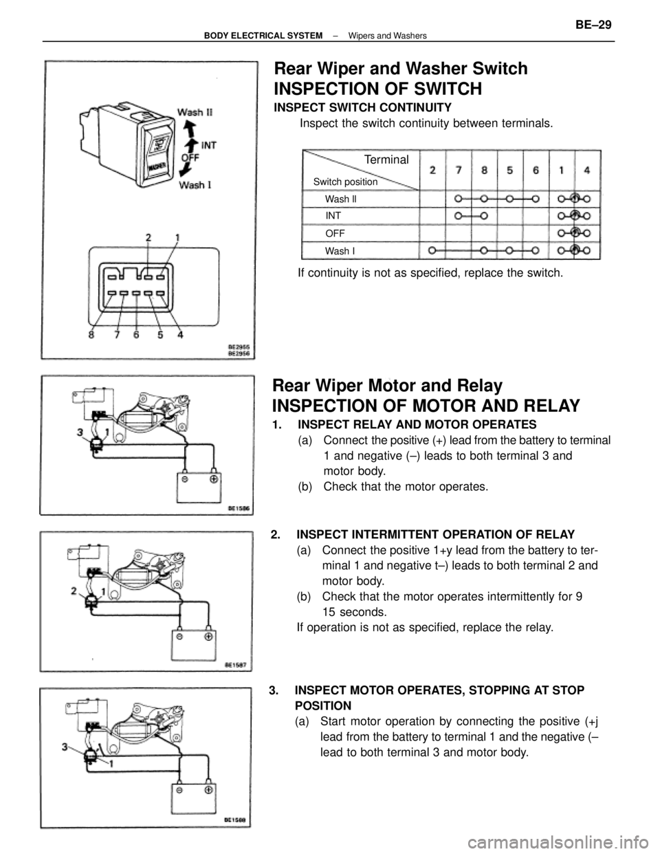
Rear Wiper Motor and Relay
INSPECTION OF MOTOR AND RELAY
1. INSPECT RELAY AND MOTOR OPERATES
(a) Connect the positive (+) lead from the battery to terminal
1 and negative (±) leads to both terminal 3 and
motor body.
(b) Check that the motor operates.
2. INSPECT INTERMITTENT OPERATION OF RELAY
(a) Connect the positive 1+y lead from the battery to ter-
minal 1 and negative t±) leads to both terminal 2 and
motor body.
(b) Check that the motor operates intermittently for 9
15 seconds.
If operation is not as specified, replace the relay.
3. INSPECT MOTOR OPERATES, STOPPING AT STOP
POSITION
(a) Start motor operation by connecting the positive (+j
lead from the battery to terminal 1 and the negative (±
lead to both terminal 3 and motor body.
Rear Wiper and Washer Switch
INSPECTION OF SWITCH
INSPECT SWITCH CONTINUITY
Inspect the switch continuity between terminals.
If continuity is not as specified, replace the switch.
Switch position
Terminal
Wash ll
Wash IOFF INT
± BODY ELECTRICAL SYSTEMWipers and WashersBE±29
Page 776 of 2389
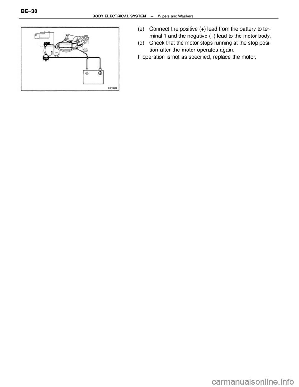
(e) Connect the positive (+) lead from the battery to ter-
minal 1 and the negative (±) lead to the motor body.
(d) Check that the motor stops running at the stop posi-
tion after the motor operates again.
If operation is not as specified, replace the motor.
± BODY ELECTRICAL SYSTEMWipers and WashersBE±30
Page 777 of 2389
Replace fuse and check for short
Replace bulb
Check switch
Check switch
Check switch
Check relay
Repair a s necessary ºDOMEº fuse blown
Bulb burned out
Door courtesy switch faulty
Unlock warning switch faulty
Buckle switch faulty
Seat belt warning relay faulty
Wiring or ground faultyºGAUGEº fuse blown
Bulb burned out
Brake fluid level warning switch faulty
Parking brake switch faulty
Wiring or ground faultyReplace fuse and check for short
Replace bulb
Check switch
Check switch
Repair as necessary ºGAUGEº fuse blown
Water temperature gauge faulty
Water temperature sender gauge faulty
Wiring or ground faulty
ºGAUGEº fuse blown
Buibburned out
oil pressure warning switch faulty
Wiring or ground faultyºGAUGEº fuse blown
Bulb burned out
Fuel level warning switch faulty
Wiring or ground faulty
Replace fuse and check for short
Replace bulb
Check switch
±Repair as necessaryReplace fuse and check for short
Replace bulb
Check switch
Repair as necessary
Replace fuse and check for short
Replace bulb
Check switch
Repair as necessaryReplace fuse and check for short
Check gauge
Check sender gauge
Repair as necessaryReplace fuse .and check for short
Check gauge
Check sender gauge
Repair as necessary
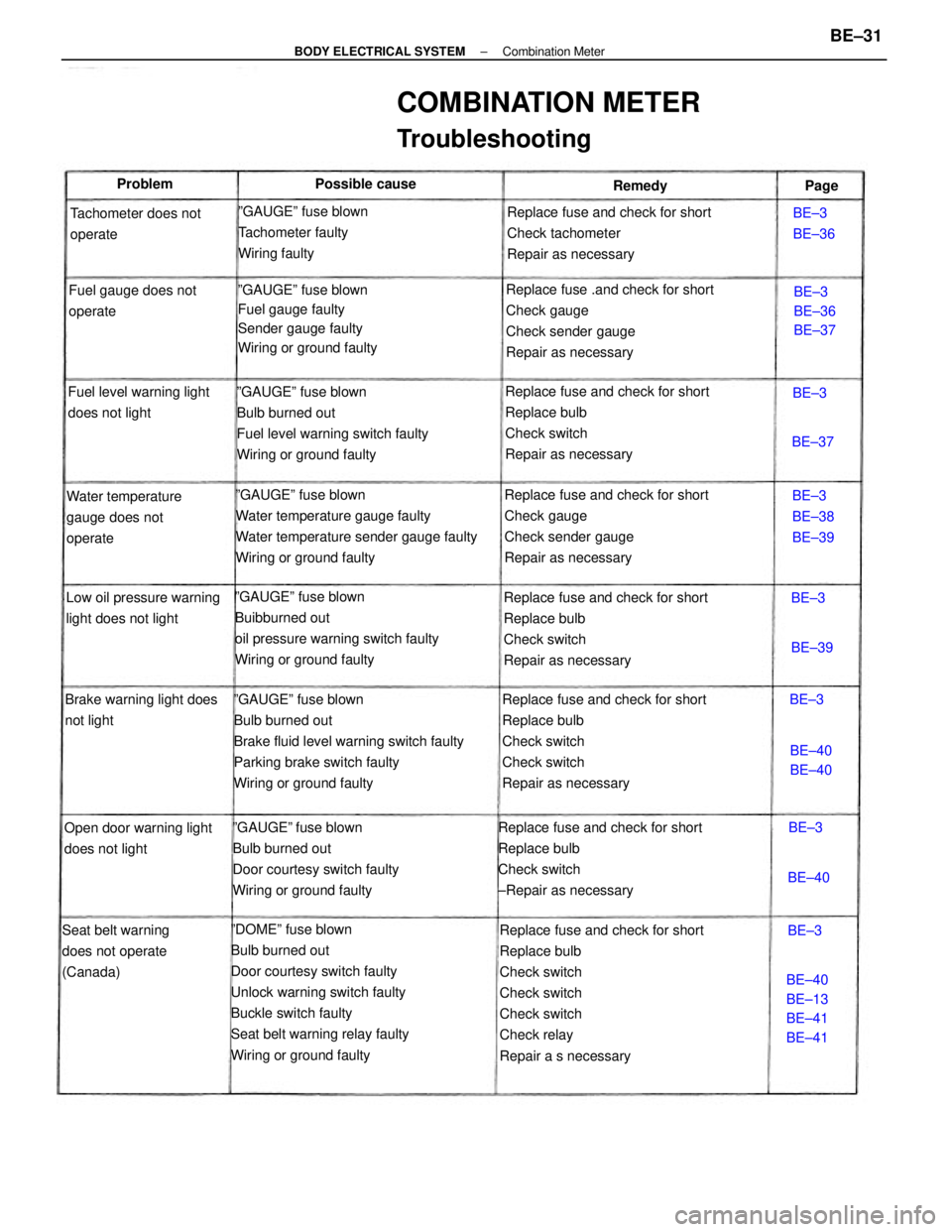
COMBINATION METER
Troubleshooting
ºGAUGEº fuse blown
Bulb burned out
Door courtesy switch faulty
Wiring or ground faultyReplace fuse and check for short
Check tachometer
Repair as necessary
ºGAUGEº fuse blown
Fuel gauge faulty
Sender gauge faulty
Wiring or ground faultyºGAUGEº fuse blown
Tachometer faulty
Wiring faulty
Low oil pressure warning
light does not lightWater temperature
gauge does not
operate
Seat belt warning
does not operate
(Canada)Tachometer does not
operate
Brake warning light does
not lightFuel gauge does not
operate
Open door warning light
does not lightFuel level warning light
does not light
BE±40
BE±13
BE±41
BE±41BE±3
BE±38
BE±39BE±3
BE±36
BE±37 Possible cause
BE±3
BE±36
BE±40
BE±40 Problem
Remedy
BE±40BE±39BE±37Page
BE±3BE±3
BE±3
BE±3
BE±3
± BODY ELECTRICAL SYSTEMCombination MeterBE±31
Page 778 of 2389
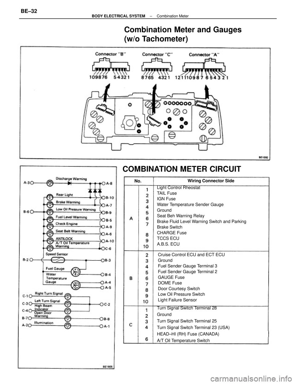
Light Control Rheostat
TAIL Fuse
IGN Fuse
Water Temperature Sender Gauge
Ground
Seat Beh Warning Relay
Brake Fluid Level Warning Switch and Parking
Brake Switch
CHARGE Fuse
TCCS ECU
A.B.S. ECU
Cruise Control ECU and ECT ECU
Ground
Fuel Sender Gauge Terminal 3
Fuel Sender Gauge Terminal 2
GAUGE Fuse
DOME Fuse
Door Courtesy Switch
Low Oil Pressure Switch
Light Failure Sensor
Combination Meter and Gauges
(w/o Tachometer)
Turn Signal Switch Terminal 28
Ground
Turn Signal Switch Terminal 25
Turn Signal Switch Terminal 23 (USA)
HEAD±HI (RH) Fuse (CANADA)
A/T Oil Temperature Switch
COMBINATION METER CIRCUIT
Wiring Connector Side
No.
± BODY ELECTRICAL SYSTEMCombination MeterBE±32
Page 779 of 2389
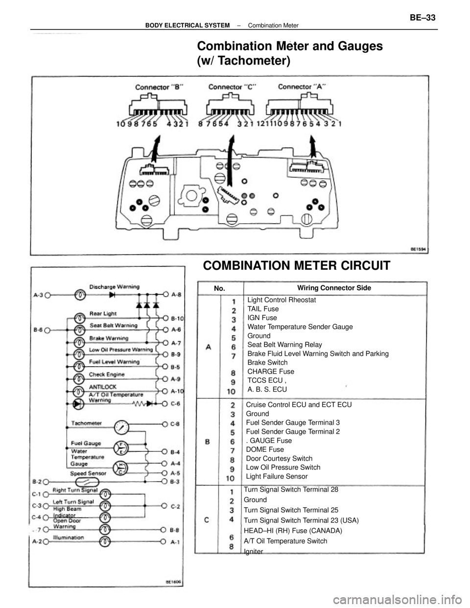
Light Control Rheostat
TAIL Fuse
IGN Fuse
Water Temperature Sender Gauge
Ground
Seat Belt Warning Relay
Brake Fluid Level Warning Switch and Parking
Brake Switch
CHARGE Fuse
TCCS ECU ,
A. B. S. ECU
Cruise Control ECU and ECT ECU
Ground
Fuel Sender Gauge Terminal 3
Fuel Sender Gauge Terminal 2
. GAUGE Fuse
DOME Fuse
Door Courtesy Switch
Low Oil Pressure Switch
Light Failure Sensor
Turn Signal Switch Terminal 28
Ground
Turn Signal Switch Terminal 25
Turn Signal Switch Terminal 23 (USA)
HEAD±HI (RH) Fuse (CANADA)
A/T Oil Temperature Switch
Igniter
Combination Meter and Gauges
(w/ Tachometer)
COMBINATION METER CIRCUIT
Wiring Connector Side
No.
± BODY ELECTRICAL SYSTEMCombination MeterBE±33
Page 780 of 2389
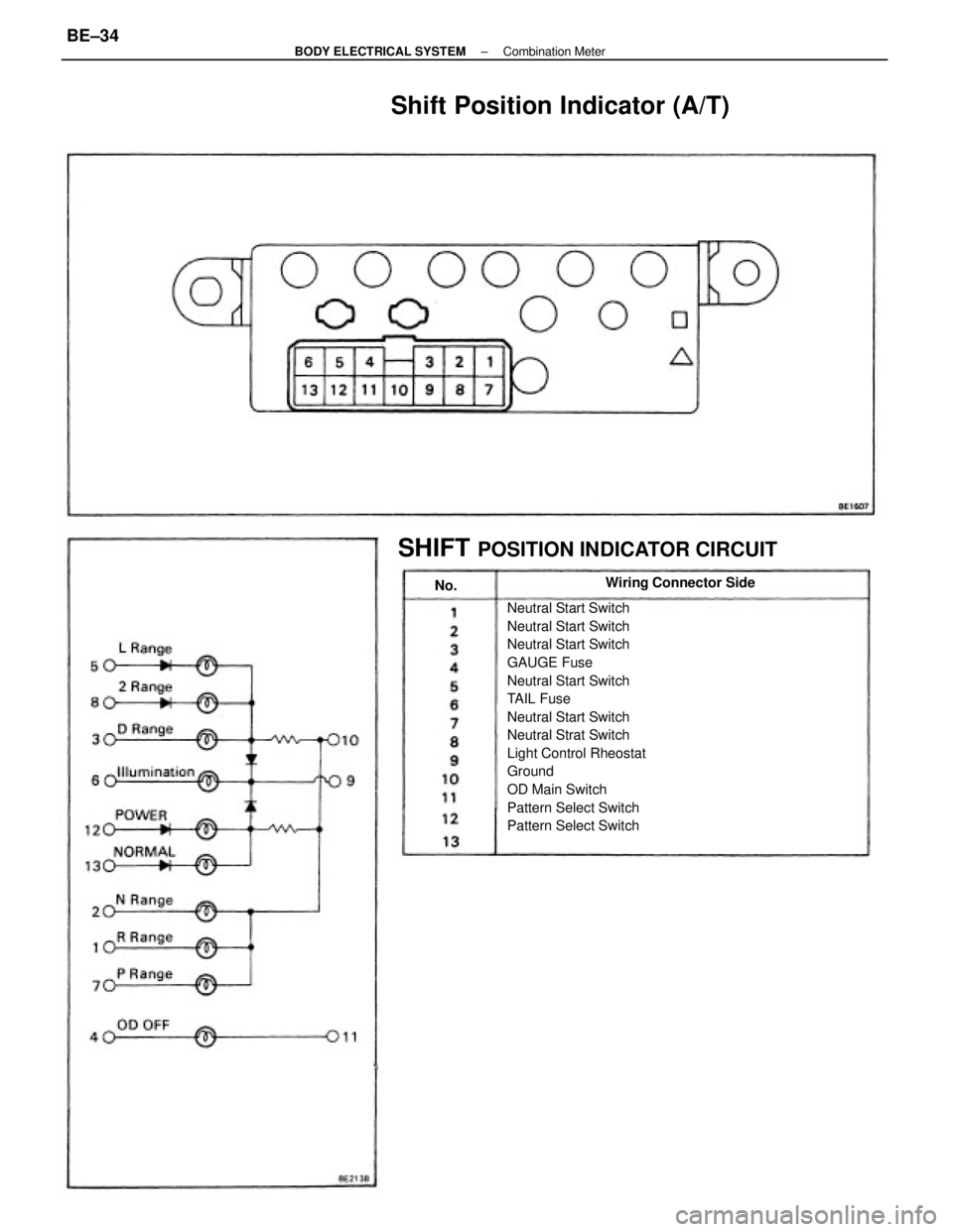
Neutral Start Switch
Neutral Start Switch
Neutral Start Switch
GAUGE Fuse
Neutral Start Switch
TAIL Fuse
Neutral Start Switch
Neutral Strat Switch
Light Control Rheostat
Ground
OD Main Switch
Pattern Select Switch
Pattern Select Switch
Shift Position Indicator (A/T)
SHIFT
POSITION INDICATOR CIRCUIT
Wiring Connector Side
No.
± BODY ELECTRICAL SYSTEMCombination MeterBE±34