TOYOTA CAMRY V20 1986 Service Information
CAMRY V20 1986
TOYOTA
TOYOTA
https://www.carmanualsonline.info/img/14/57449/w960_57449-0.png
TOYOTA CAMRY V20 1986 Service Information
Trending: checking oil, spark plugs replace, sensor, windshield wipers, gas type, boot, change time
Page 731 of 2389
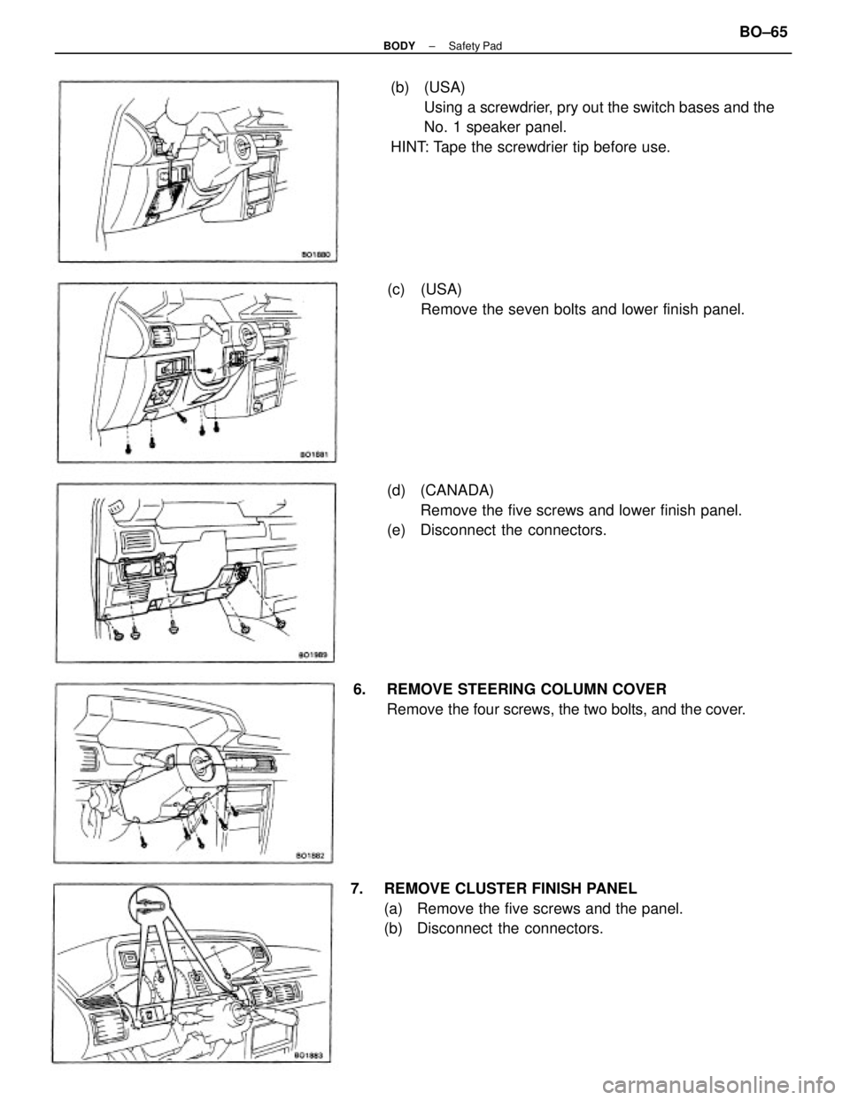
(b) (USA)
Using a screwdrier, pry out the switch bases and the
No. 1 speaker panel.
HINT: Tape the screwdrier tip before use.
7. REMOVE CLUSTER FINISH PANEL
(a) Remove the five screws and the panel.
(b) Disconnect the connectors.(d) (CANADA)
Remove the five screws and lower finish panel.
(e) Disconnect the connectors.(c) (USA)
Remove the seven bolts and lower finish panel.
6. REMOVE STEERING COLUMN COVER
Remove the four screws, the two bolts, and the cover.
± BODYSafety PadBO±65
Page 732 of 2389
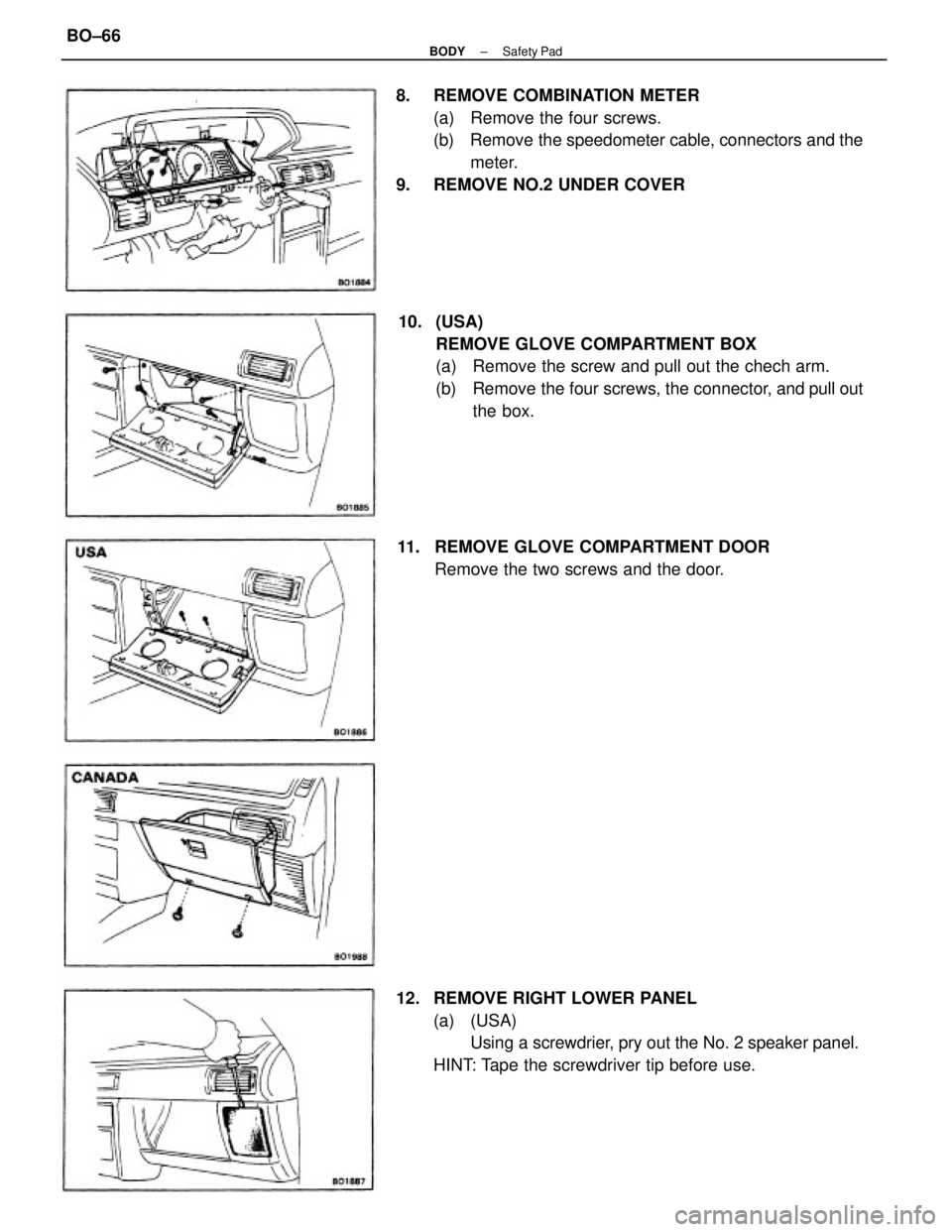
8. REMOVE COMBINATION METER
(a) Remove the four screws.
(b) Remove the speedometer cable, connectors and the
meter.
9. REMOVE NO.2 UNDER COVER
10. (USA)
REMOVE GLOVE COMPARTMENT BOX
(a) Remove the screw and pull out the chech arm.
(b) Remove the four screws, the connector, and pull out
the box.
12. REMOVE RIGHT LOWER PANEL
(a) (USA)
Using a screwdrier, pry out the No. 2 speaker panel.
HINT: Tape the screwdriver tip before use. 11. REMOVE GLOVE COMPARTMENT DOOR
Remove the two screws and the door.
± BODYSafety PadBO±66
Page 733 of 2389
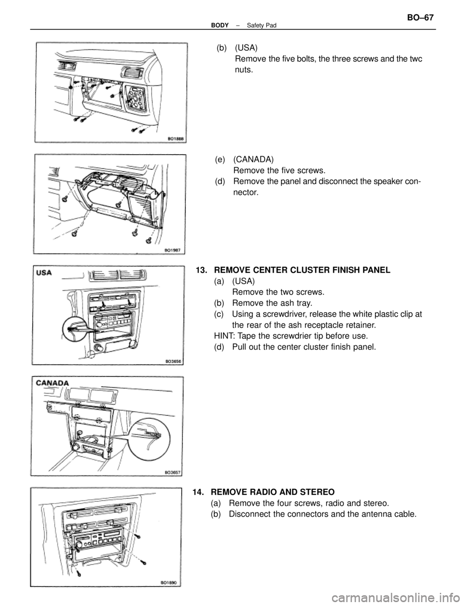
13. REMOVE CENTER CLUSTER FINISH PANEL
(a) (USA)
Remove the two screws.
(b) Remove the ash tray.
(c) Using a screwdriver, release the white plastic clip at
the rear of the ash receptacle retainer.
HINT: Tape the screwdrier tip before use.
(d) Pull out the center cluster finish panel.(e) (CANADA)
Remove the five screws.
(d) Remove the panel and disconnect the speaker con-
nector.
14. REMOVE RADIO AND STEREO
(a) Remove the four screws, radio and stereo.
(b) Disconnect the connectors and the antenna cable.(b) (USA)
Remove the five bolts, the three screws and the twc
nuts.
± BODYSafety PadBO±67
Page 734 of 2389
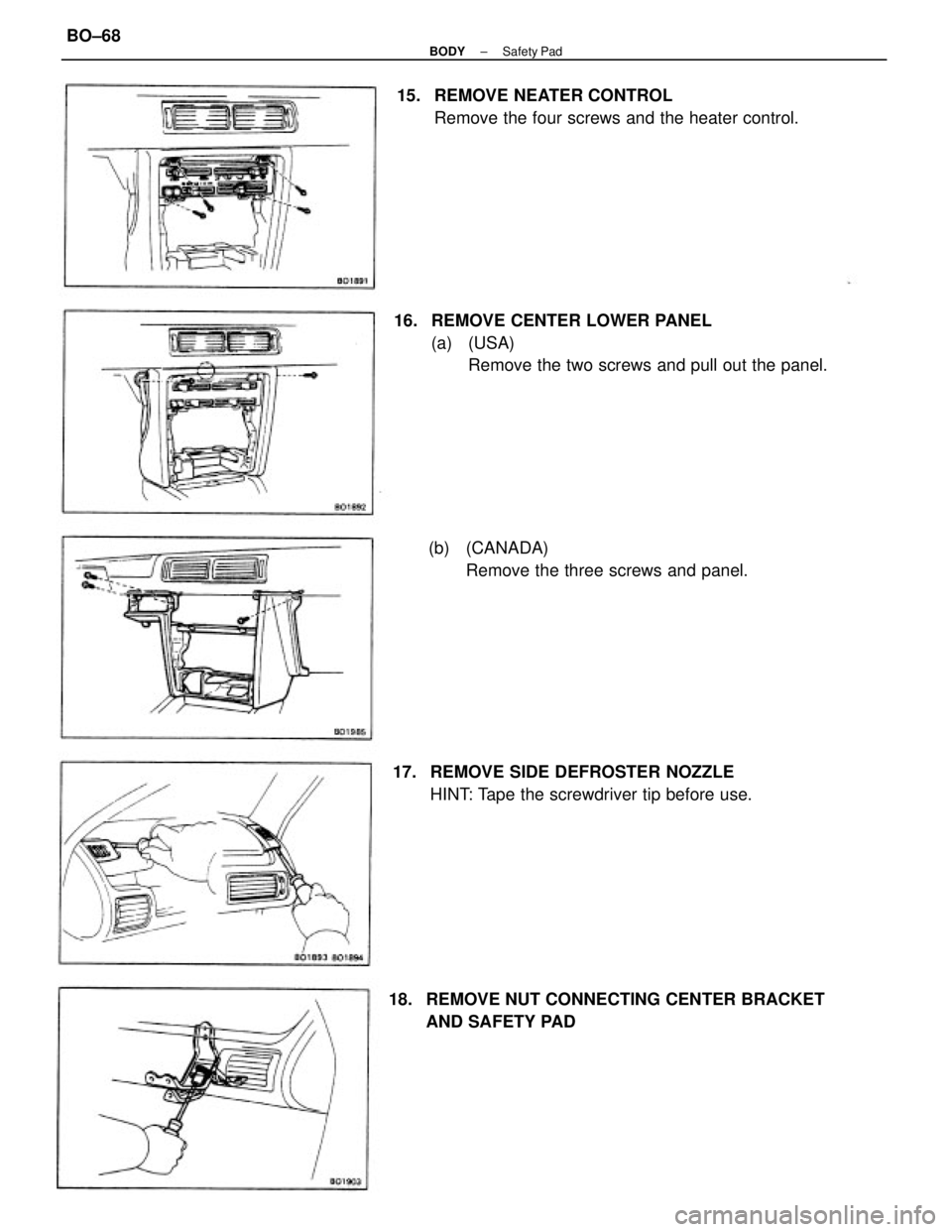
16. REMOVE CENTER LOWER PANEL
(a) (USA)
Remove the two screws and pull out the panel. 15. REMOVE NEATER CONTROL
Remove the four screws and the heater control.
18. REMOVE NUT CONNECTING CENTER BRACKET
AND SAFETY PAD 17. REMOVE SIDE DEFROSTER NOZZLE
HINT: Tape the screwdriver tip before use. (b) (CANADA)
Remove the three screws and panel.
± BODYSafety PadBO±68
Page 735 of 2389
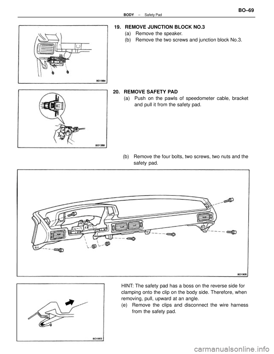
HINT: The safety pad has a boss on the reverse side for
clamping onto the clip on the body side. Therefore, when
removing, pull, upward at an angle.
(e) Remove the clips and disconnect the wire harness
from the safety pad. 19. REMOVE JUNCTION BLOCK NO.3
(a) Remove the speaker.
(b) Remove the two screws and junction block No.3.
20. REMOVE SAFETY PAD
(a) Push on the pawls of speedometer cable, bracket
and pull it from the safety pad.
(b) Remove the four bolts, two screws, two nuts and the
safety pad.
± BODYSafety PadBO±69
Page 736 of 2389
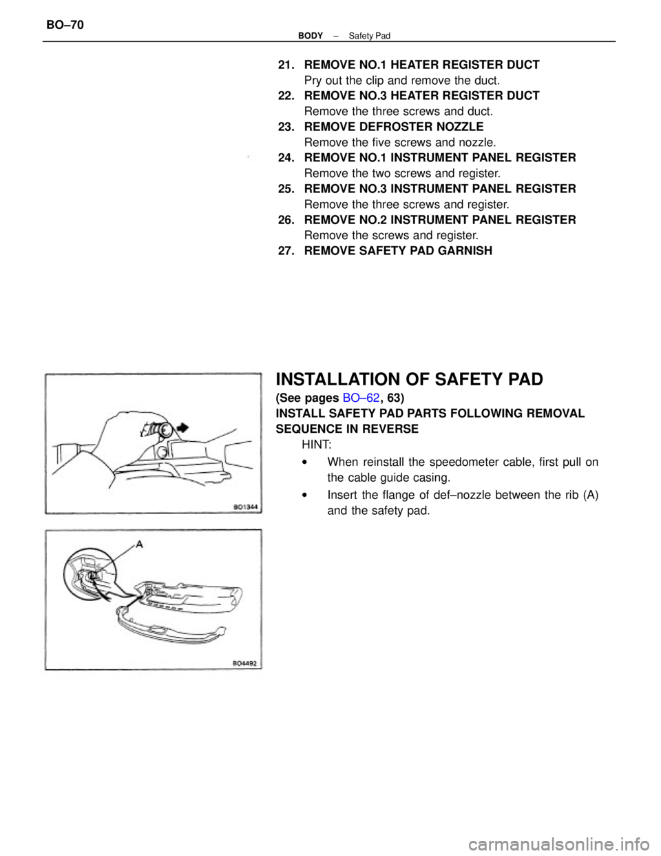
21. REMOVE NO.1 HEATER REGISTER DUCT
Pry out the clip and remove the duct.
22. REMOVE NO.3 HEATER REGISTER DUCT
Remove the three screws and duct.
23. REMOVE DEFROSTER NOZZLE
Remove the five screws and nozzle.
24. REMOVE NO.1 INSTRUMENT PANEL REGISTER
Remove the two screws and register.
25. REMOVE NO.3 INSTRUMENT PANEL REGISTER
Remove the three screws and register.
26. REMOVE NO.2 INSTRUMENT PANEL REGISTER
Remove the screws and register.
27. REMOVE SAFETY PAD GARNISH
INSTALLATION OF SAFETY PAD
(See pages BO±62, 63)
INSTALL SAFETY PAD PARTS FOLLOWING REMOVAL
SEQUENCE IN REVERSE
HINT:
wWhen reinstall the speedometer cable, first pull on
the cable guide casing.
wInsert the flange of def±nozzle between the rib (A)
and the safety pad.
± BODYSafety PadBO±70
Page 737 of 2389
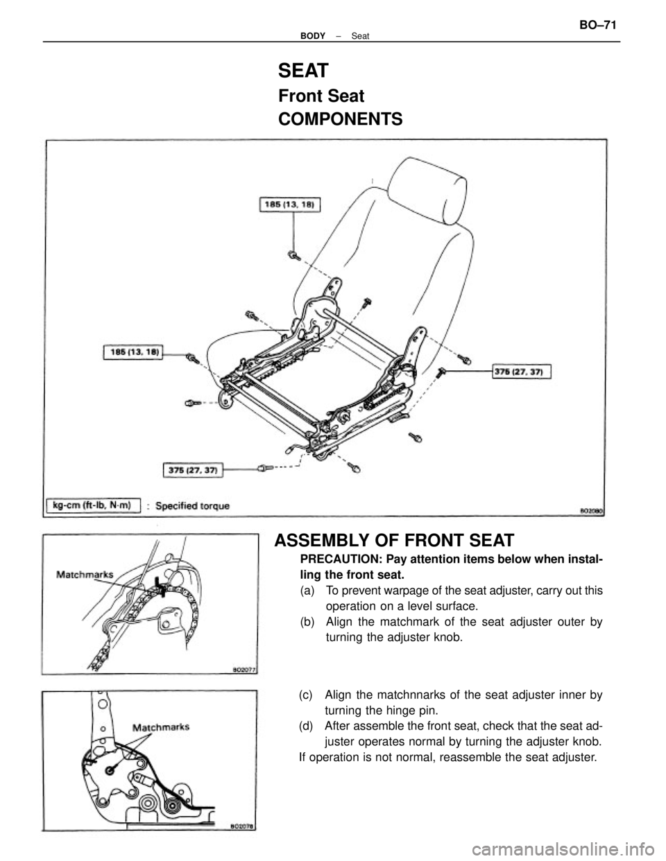
ASSEMBLY OF FRONT SEAT
PRECAUTION: Pay attention items below when instal-
ling the front seat.
(a) To prevent warpage of the seat adjuster, carry out this
operation on a level surface.
(b) Align the matchmark of the seat adjuster outer by
turning the adjuster knob.
(c) Align the matchnnarks of the seat adjuster inner by
turning the hinge pin.
(d) After assemble the front seat, check that the seat ad-
juster operates normal by turning the adjuster knob.
If operation is not normal, reassemble the seat adjuster.
SEAT
Front Seat
COMPONENTS
± BODYSeatBO±71
Page 738 of 2389
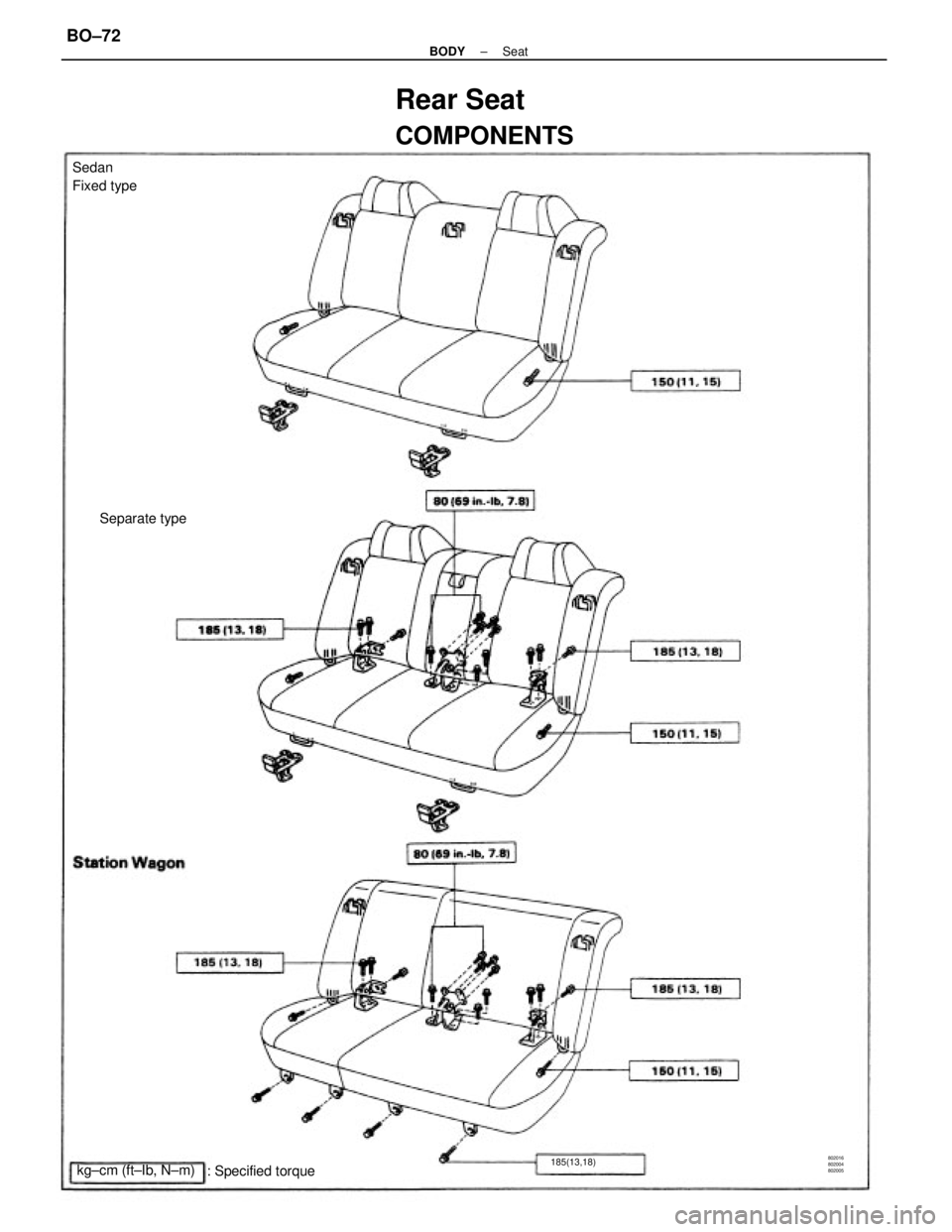
Rear Seat
COMPONENTS
Sedan
Fixed type
: Specified torque kg±cm (ft±Ib, N±m)Separate type
185(13,18)802016
802004
802005
± BODYSeatBO±72
Page 739 of 2389
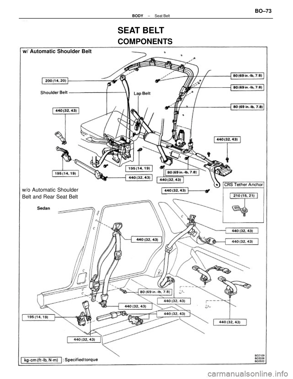
SEAT BELT
COMPONENTS
w/o Automatic Shoulder
Belt and Rear Seat Beltw/ Automatic Shoulder Belt
± BODYSeat BeltBO±73
Page 740 of 2389
FRONT AND REAR SEAT BELT
[Emergency Locking Retractor (ELR) Type]
1. RUNNING TEST (IN SAFE AREA)
(a) Fasten the front seat belt.
(b) Drive the car at 10 mph (16km/h) and make a very
hard stop.
(e) Check that the belt is locked and cannot be extended
at this time.
HINT: Conduct this test in a safe area. If the belt does not
lock, remove the belt mechanism assembly and conduct
the following static check. Also, whenever installing a
new belt assembly, verify proper operation before installa±
tion.
2. STATIC TEST
(a) Remove the locking retractor assembly.
(b) Tilt the retractor slowly.
(e) Verify that the belt can be pulled out at a tilt of 15
degrees or less, and cannot be pulled out at over 45
degrees of tilt.
If a problem is found, replace the assembly.
COMPONENTS (Cont'd)
± BODYSeat BeltBO±74
Trending: coolant, heater, transmission, brake sensor, fuel tank capacity, key, recommended oil
![TOYOTA CAMRY V20 1986 Service Information FRONT AND REAR SEAT BELT
[Emergency Locking Retractor (ELR) Type]
1. RUNNING TEST (IN SAFE AREA)
(a) Fasten the front seat belt.
(b) Drive the car at 10 mph (16km/h) and make a very
hard stop.
(e) TOYOTA CAMRY V20 1986 Service Information FRONT AND REAR SEAT BELT
[Emergency Locking Retractor (ELR) Type]
1. RUNNING TEST (IN SAFE AREA)
(a) Fasten the front seat belt.
(b) Drive the car at 10 mph (16km/h) and make a very
hard stop.
(e)](/img/14/57449/w960_57449-739.png)