TOYOTA RAV4 1996 Service Repair Manual
Manufacturer: TOYOTA, Model Year: 1996, Model line: RAV4, Model: TOYOTA RAV4 1996Pages: 1632, PDF Size: 41.64 MB
Page 241 of 1632
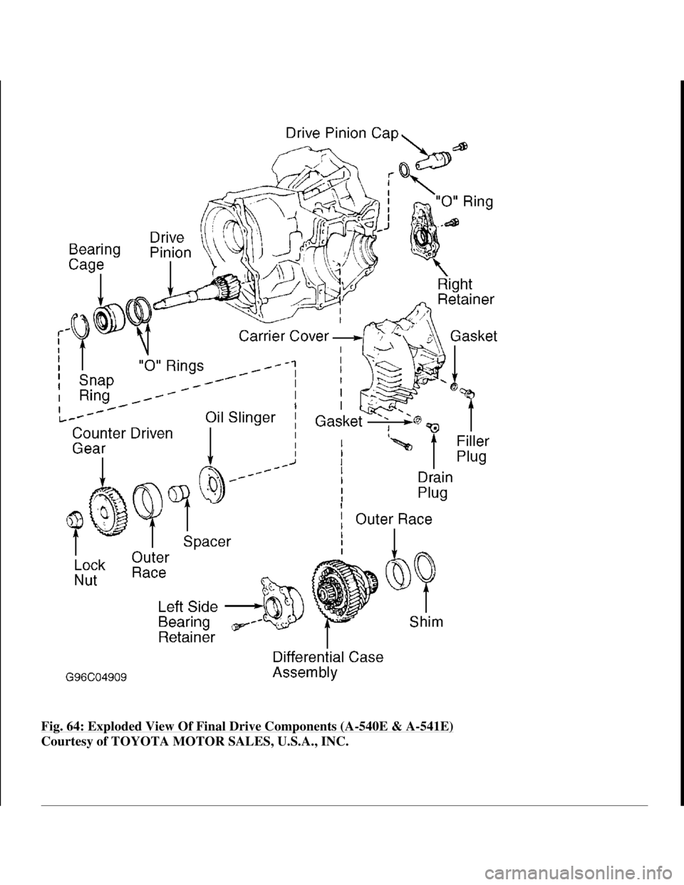
Fig. 64: Exploded View Of Final Drive Components (A-540E & A-541E)
Courtesy of TOYOTA MOTOR SALES, U.S.A., INC.
1998 Toyota Avalon XLS
1997-99 AUTOMATIC TRANSMISSIONS Toyota A-540E, A-540H & A-541E Overhaul
Helpmelearn
November-03-08 10:28:20 AMPage 87 © 2005 Mitchell Repair Information Company, LLC.
Page 242 of 1632
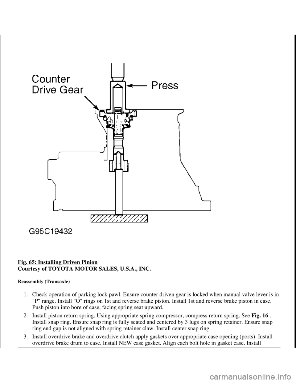
Fig. 65: Installing Driven Pinion
Courtesy of TOYOTA MOTOR SALES, U.S.A., INC.
Reassembly (Transaxle)
1. Check operation of parking lock pawl. Ensure counter driven gear is locked when manual valve lever is in
"P" range. Install "O" rings on 1st and reverse brake piston. Install 1st and reverse brake piston in case.
Push piston into bore of case, facing spring seat upward.
2. Install piston return spring. Using appropriate spring compressor, compress return spring. See Fig. 16
.
Install snap ring. Ensure snap ring is fully seated and centered by 3 lugs on spring retainer. Ensure snap
ring end gap is not aligned with spring retainer claw. Install center snap ring.
3. Install overdrive brake and overdrive clutch apply gaskets over appropriate case opening (ports). Install
overdrive brake drum to case. Install NEW case
gasket. Align each bolt hole in gasket case. Install
1998 Toyota Avalon XLS
1997-99 AUTOMATIC TRANSMISSIONS Toyota A-540E, A-540H & A-541E Overhaul
Helpmelearn
November-03-08 10:28:20 AMPage 88 © 2005 Mitchell Repair Information Company, LLC.
Page 243 of 1632
overdrive assembly over gasket to transaxle case. Coat threads of 23 mm bolts with sealer. See Fig. 66.
Tighten bolts to specification. See TORQUE SPECIFICATIONS
.
4. Check intermediate shaft end play (axial). See Fig. 67
. End play should be .019-.059" (.47-1.50 mm).
Ensure shaft turns smoothly. If end play is not within specification, check installation of intermediate
shaft.
5. Install rear planetary ring gear. Place bearing on ring gear. Coat thrust washer with petroleum jelly and
install on rear planetary gear. Install rear planetary gear. See Fig. 28
.
6. Install 1st and reverse brake discs, plates and flange. See Fig. 14
. Start with plate, alternating with disc,
and ending with disc. Install outer flange with flat side facing toward piston side. Install snap ring. Ensure
snap ring end-gap is not aligned with cutouts.
7. Check operation of 1st and reverse brake. Apply compressed air at oil passage of transaxle case to
confirm piston movement. See Fig. 15
. Check pack clearance of 1st and reverse brake. Clearance for A-
540E is .33-.081" (.85-2.05 mm). Clearance for A-540H is .041-.085" (1.04-2.16 mm). Clearance for A-
541E is .076-.106" (1.92-2.86 mm). See Fig. 68
.
8. Install No. 2 one-way clutch in case. Install one-way clutch while turning planetary gear clockwise with
snap ring expander. Check operation of No. 2 one-way clutch by turning planetary gear. Gear should turn
freely clockwise and lock counterclockwise. See Fig. 69
. Install snap ring. Ensure end gap is not aligned
with cutouts.
9. Install thrust washer on rear planetary gear. Install 2nd coast brake band guide with correct bolt. Place
thrust washer on No. 1 one-way clutch. Install No. 1 one-way clutch into rear planetary gear.
10. Install 2nd brake flange with flat end facing up. Install 2nd brake discs and plates, starting with disc and
ending with plate. Place piston return spring in case. Place 2nd brake drum in case. Ensure groove of
drum is aligned with bolt. While compressing piston return springs over drum with hammer handles,
install snap ring in groove. Ensure snap ring end gap is not aligned with cutouts.
11. Install NEW 2nd brake gasket until contact is made with 2nd brake drum. See Fig. 14
. Check operation
of 2nd brake by applying compressed air into oil passage. Make sure the piston moves freely. See Fig.
13 .
12. Install thrust washer on sun gear input drum (shell). Install sun gear by turning clockwise and installing in
No. 1 one-way clutch. Install oil seal ring to intermediate shaft. Install front planetary gear with bearing
on both sides of gear on sun gear. Install front planetary ring gear onto sun gear.
13. Install 2nd coast brake band into case. Install pin through oil pump mounting bolt hole. Install thrust
bearings on both sides of forward clutch. Install thrust washer with oil groove facing upward onto direct
clutch drum.
14. Mesh hub of forward clutch with flukes of direct clutch discs. Ensure bearing and thrust washer do not
move out of place. Install direct and forward clutch into case. Hold direct clutch toward forward clutch to
prevent thrust washer from moving out of place. Check distance between direct clutch drum and sun gear
input drum. See Fig. 70
. Distance should be .12" (3 mm). NOTE: For thrust bearing and race location and identification, see Fig. 73
and Fig.
74 .
1998 Toyota Avalon XLS
1997-99 AUTOMATIC TRANSMISSIONS Toyota A-540E, A-540H & A-541E Overhaul
Helpmelearn
November-03-08 10:28:20 AMPage 89 © 2005 Mitchell Repair Information Company, LLC.
Page 244 of 1632
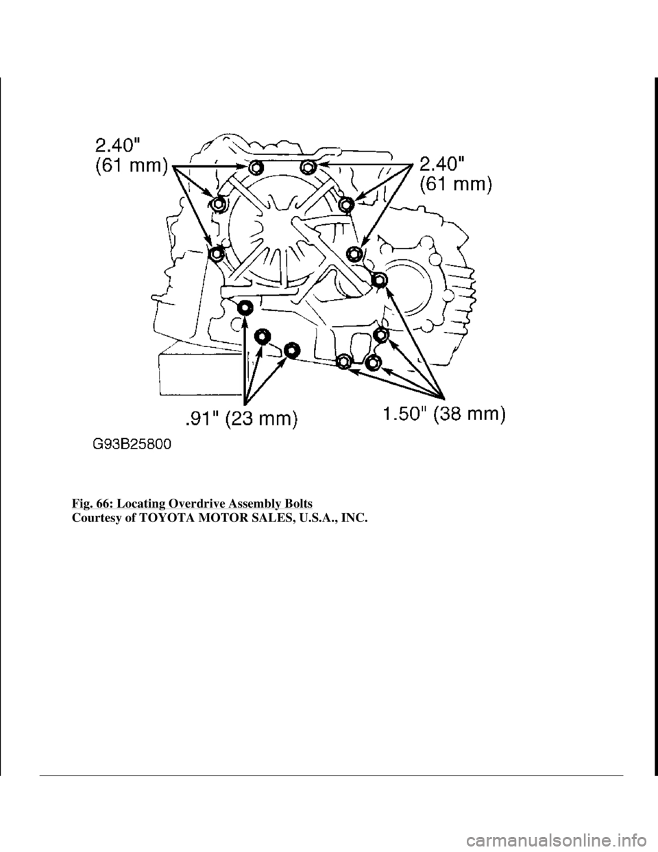
Fig. 66: Locating Overdrive Assembly Bolts
Courtesy of TOYOTA MOTOR SALES, U.S.A., INC.
1998 Toyota Avalon XLS
1997-99 AUTOMATIC TRANSMISSIONS Toyota A-540E, A-540H & A-541E Overhaul
Helpmelearn
November-03-08 10:28:20 AMPage 90 © 2005 Mitchell Repair Information Company, LLC.
Page 245 of 1632
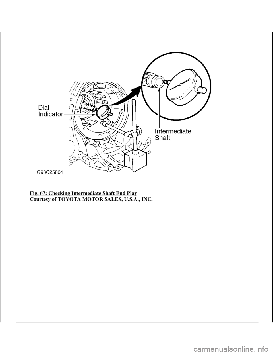
Fig. 67: Checking Intermediate Shaft End Play
Courtesy of TOYOTA MOTOR SALES, U.S.A., INC.
1998 Toyota Avalon XLS
1997-99 AUTOMATIC TRANSMISSIONS Toyota A-540E, A-540H & A-541E Overhaul
Helpmelearn
November-03-08 10:28:20 AMPage 91 © 2005 Mitchell Repair Information Company, LLC.
Page 246 of 1632
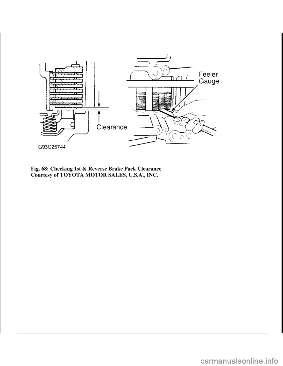
Fig. 68: Checking 1st & Reverse Brake Pack Clearance
Courtesy of TOYOTA MOTOR SALES, U.S.A., INC.
1998 Toyota Avalon XLS
1997-99 AUTOMATIC TRANSMISSIONS Toyota A-540E, A-540H & A-541E Overhaul
Helpmelearn
November-03-08 10:28:20 AMPage 92 © 2005 Mitchell Repair Information Company, LLC.
Page 247 of 1632
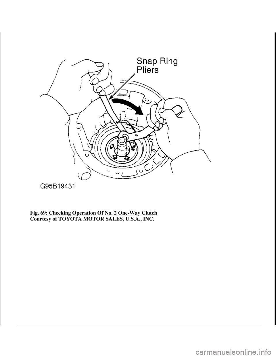
Fig. 69: Checking Operation Of No. 2 One-Way Clutch
Courtesy of TOYOTA MOTOR SALES, U.S.A., INC.
1998 Toyota Avalon XLS
1997-99 AUTOMATIC TRANSMISSIONS Toyota A-540E, A-540H & A-541E Overhaul
Helpmelearn
November-03-08 10:28:20 AMPage 93 © 2005 Mitchell Repair Information Company, LLC.
Page 248 of 1632
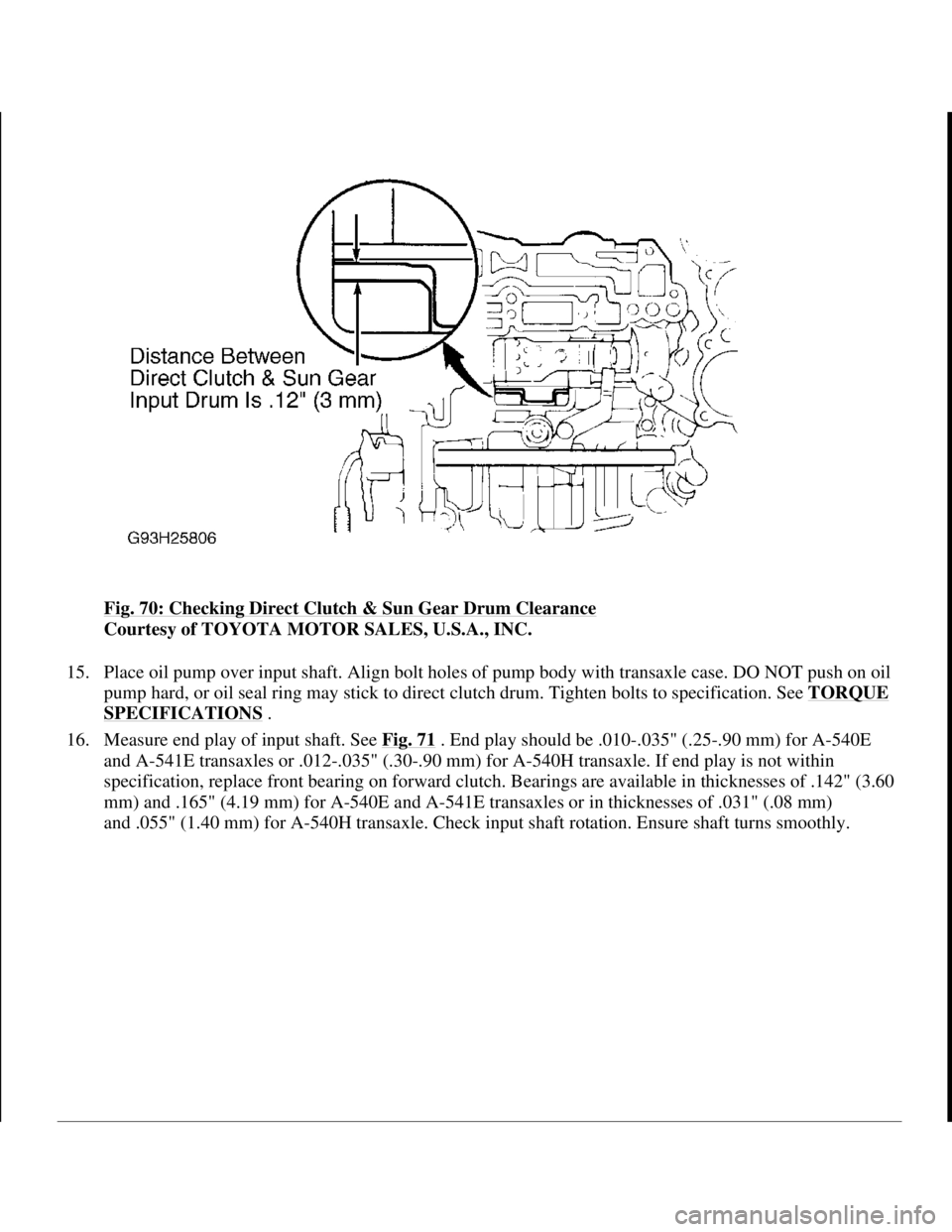
Fig. 70: Checking Direct Clutch & Sun Gear Drum Clearance
Courtesy of TOYOTA MOTOR SALES, U.S.A., INC.
15. Place oil pump over input shaft. Align bolt holes of pump body with transaxle case. DO NOT push on oil
pump hard, or oil seal ring may stick to direct clutch drum. Tighten bolts to specification. See TORQUE
SPECIFICATIONS .
16. Measure end play of input shaft. See Fig. 71
. End play should be .010-.035" (.25-.90 mm) for A-540E
and A-541E transaxles or .012-.035" (.30-.90 mm) for A-540H transaxle. If end play is not within
specification, replace front bearing on forward clutch. Bearings are available in thicknesses of .142" (3.60
mm) and .165" (4.19 mm) for A-540E and A-541E transaxles or in thicknesses of .031" (.08 mm)
and .055" (1.40 mm) for A-540H transaxle. Check input shaft rotation. Ensure shaft turns smoothl
y.
1998 Toyota Avalon XLS
1997-99 AUTOMATIC TRANSMISSIONS Toyota A-540E, A-540H & A-541E Overhaul
Helpmelearn
November-03-08 10:28:20 AMPage 94 © 2005 Mitchell Repair Information Company, LLC.
Page 249 of 1632
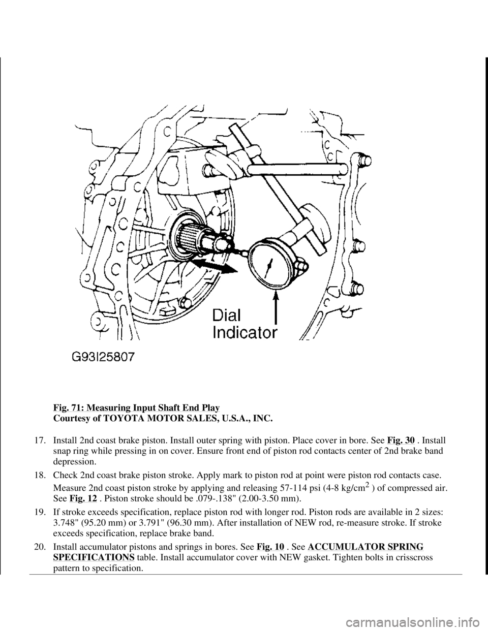
Fig. 71: Measuring Input Shaft End Play
Courtesy of TOYOTA MOTOR SALES, U.S.A., INC.
17. Install 2nd coast brake piston. Install outer spring with piston. Place cover in bore. See Fig. 30
. Install
snap ring while pressing in on cover. Ensure front end of piston rod contacts center of 2nd brake band
depression.
18. Check 2nd coast brake piston stroke. Apply mark to piston rod at point were piston rod contacts case.
Measure 2nd coast piston stroke by applying and releasing 57-114 psi (4-8 kg/cm
2 ) of compressed air.
See Fig. 12
. Piston stroke should be .079-.138" (2.00-3.50 mm).
19. If stroke exceeds specification, replace piston rod with longer rod. Piston rods are available in 2 sizes:
3.748" (95.20 mm) or 3.791" (96.30 mm). After installation of NEW rod, re-measure stroke. If stroke
exceeds specification, replace brake band.
20. Install accumulator pistons and springs in bores. See Fig. 10
. See ACCUMULATOR SPRING
SPECIFICATIONS table. Install accumulator cover with NEW gasket. Tighten bolts in crisscross
pattern to specification.
1998 Toyota Avalon XLS
1997-99 AUTOMATIC TRANSMISSIONS Toyota A-540E, A-540H & A-541E Overhaul
Helpmelearn
November-03-08 10:28:20 AMPage 95 © 2005 Mitchell Repair Information Company, LLC.
Page 250 of 1632
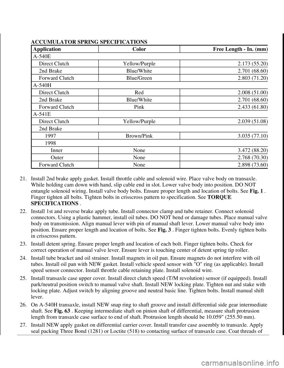
ACCUMULATOR SPRING SPECIFICATIONS
21. Install 2nd brake apply gasket. Install throttle cable and solenoid wire. Place valve body on transaxle.
While holding cam down with hand, slip cable end in slot. Lower valve body into position. DO NOT
entangle solenoid wiring. Install valve body bolts. Ensure proper length and location of bolts. See Fig. 1
.
Finger tighten all bolts. Tighten bolts in crisscross pattern to specification. See TORQUE
SPECIFICATIONS .
22. Install 1st and reverse brake apply tube. Install connector clamp and tube retainer. Connect solenoid
connectors. Using a plastic hammer, install oil tubes. DO NOT bend or damage tubes. Place manual valve
body on transmission. Align manual lever with pin of manual shaft lever. Lower manual valve body into
position. Ensure proper length and location of bolts. See Fig. 3
. Finger tighten bolts. Evenly tighten bolts
in crisscross pattern.
23. Install detent spring. Ensure proper length and location of each bolt. Finger tighten bolts. Check for
correct operation of manual valve lever. Ensure lever is touching center of detent spring tip roller.
24. Install tube bracket and oil strainer. Install magnets in oil pan. Ensure magnets do not interfere with oil
tubes. Install oil pan with NEW gasket. Install vehicle speed sensor with "O" ring (as applicable). Install
speed sensor connector. Install throttle cable retaining plate. Install solenoid wire.
25. Install transaxle case upper cover. Install direct clutch speed (T/M revolution) sensor (if equipped). Install
park/neutral position switch to manual valve shaft. Install NEW locking plate. Tighten nut and stake with
locking plate. Adjust switch by aligning groove and neutral basic line. Tighten bolts. Install manual shift
lever.
26. On A-540H transaxle, install NEW snap ring to shaft groove and install differential side gear intermediate
shaft. See Fig. 63
. Keeping intermediate shaft on pinion shaft of differential, measure shaft protrusion
length from transaxle case surface to end of shaft. Protrusion length should be 10.059" (255.50 mm).
27. Install NEW apply gasket on differential carrier cover. Install transfer case assembly to transaxle. Apply
seal packing Three Bond (1281) or Loctite (518) to contacting surface of transaxle case. Coat threads of
ApplicationColorFree Length - In. (mm)
A-540E
Direct ClutchYellow/Purple2.173 (55.20)
2nd BrakeBlue/White2.701 (68.60)
Forward ClutchBlue/Green2.803 (71.20)
A-540H
Direct ClutchRed2.008 (51.00)
2nd BrakeBlue/White2.701 (68.60)
Forward ClutchPink2.433 (61.80)
A-541E
Direct ClutchYellow/Purple2.039 (51.08)
2nd Brake
1997Brown/Pink3.035 (77.10)
1998
InnerNone3.472 (88.20)
OuterNone2.768 (70.30)
Forward ClutchNone2.898 (73.60)
1998 Toyota Avalon XLS
1997-99 AUTOMATIC TRANSMISSIONS Toyota A-540E, A-540H & A-541E Overhaul
Helpmelearn
November-03-08 10:28:20 AMPage 96 © 2005 Mitchell Repair Information Company, LLC.