light TOYOTA RAV4 1996 Service Owner's Guide
[x] Cancel search | Manufacturer: TOYOTA, Model Year: 1996, Model line: RAV4, Model: TOYOTA RAV4 1996Pages: 1632, PDF Size: 41.64 MB
Page 82 of 1632
Removal & Installation
1. Before proceeding, see SERVICE PRECAUTIONS . Turn ignition switch to LOCK position.
Disconnect negative battery cable. Wait at least 90 seconds.
2. Remove glove box door. Disconnect passenger-side air bag module connector. See Fig. 3
. Remove
instrument panel. See INSTRUMENT PANEL
. Working from reverse side of instrument panel, remove
2 bolts and passenger-side air bag module. Remove 3 bolts and pry up 7 clips and remove air bag door.
3. To install, reverse removal procedure. Tighten passenger-side air bag bolts to specification. See
TORQUE SPECIFICATIONS
. There should be no interference between passenger-side air bag door
and instrument panel and clearance should be uniform. Check AIR BAG warning light to ensure system
is functioning properly. See SYSTEM OPERATION CHECK
.
SEAT BELT PRETENSIONERS
Removal & Installation
1. Before proceeding, see SERVICE PRECAUTIONS . Turn ignition switch to LOCK position.
Disconnect negative battery cable. Wait at least 90 seconds.
2. On 2-door models, remove rear seat, rear floor finish panel front door scuff plate, quarter trim and roof
side inner garnish. On 4-door models, remove rear door scuff plate, front door scuff plate and center pillar
lower garnish.
3. On all models, remove bolts and floor anchor. Tape tip of screwdriver and remove seat belt assembly
anchor caps. Remove bolt and shoulder anchor. Disconnect pretensioner connector. Remove 2 bolts and
seat belt pretensioner assembly.
4. To install, reverse removal procedure. Tighten fasteners to specification. See TORQUE
SPECIFICATIONS . Check AIR BAG warning light to ensure system is functioning properly. See
SYSTEM OPERATION CHECK
.
SPIRAL CABLE
Removal & Installation
1. Before proceeding, see SERVICE PRECAUTIONS . Turn ignition switch to LOCK position.
Disconnect negative battery cable. Wait at least 90 seconds. Remove driver-side air bag module. See
DRIVER
-SIDE AIR BAG MODULE .
2. Remove steering wheel. See STEERING WHEEL
. Remove lower steering column cover. Disconnect
lower spiral cable connector. Remove 4 screws and spiral cable.
3. To install, reverse removal procedure. Before installing spiral cable, ensure front wheels are in straight-
ahead position and spiral cable is properly aligned. See SPIRAL CABLE under ADJUSTMENTS
.
Tighten steering wheel nut and driver-side air bag module screws to specification. See TORQUE
SPECIFICATIONS . Check AIR BAG warning light to ensure system is functioning properly. See
SYSTEM OPERATION CHECK
.
STEERING COLUMN
Removal & Installation
1999 Toyota RAV4
AIR BAG RESTRAINT SYSTEM 1999 Toyota
Microsoft
Sunday, November 22, 2009 10:33:22 AMPage 19 © 2005 Mitchell Repair Information Company, LLC.
Page 83 of 1632
1. Before proceeding, see SERVICE PRECAUTIONS . Ensure front wheels are in straight-ahead position.
Turn ignition switch to LOCK position. Disconnect negative battery cable. Wait at least 90 seconds.
Remove steering wheel. See STEERING WHEEL
.
2. Remove lower finish panel and instrument panel lower insert. Remove upper and lower steering column
covers. Disconnect and remove combination switch with spiral cable attached. Remove heater-to-register
duct. Match mark steering shaft and steering gear shaft for reassembly performance. Remove steering
column.
3. To install, reverse removal procedure. Tighten fasteners to specification. See TORQUE
SPECIFICATIONS . Check AIR BAG warning light to ensure system is functioning properly. See
SYSTEM OPERATION CHECK
.
STEERING WHEEL
Removal & Installation
1. Before proceeding, see SERVICE PRECAUTIONS . Ensure front wheels are in straight-ahead position.
Turn ignition switch to LOCK position. Disconnect negative battery cable. Wait at least 90 seconds.
Remove driver-side air bag module. See DRIVER
-SIDE AIR BAG MODULE .
2. Remove steering wheel nut. Match mark steering wheel and steering column for reassembly reference.
Using appropriate puller, remove steering wheel.
3. To install, reverse removal procedure. Ensure front wheels are in straight-ahead position and spiral cable
is properly aligned. See SPIRAL CABLE under ADJUSTMENTS
. Tighten steering wheel nut and
driver-side air bag module screws to specification. See TORQUE SPECIFICATIONS
. Check AIR
BAG warning light to ensure system is functioning properly. See SYSTEM OPERATION CHECK
.
SYSTEM OPERATION CHECK
Turn ignition switch to ACC or ON position. AIR BAG warning light should come on for about 6 seconds and
then go out. If AIR BAG warning light does not operate as specified, see DIAGNOSIS & TESTING
.
DIAGNOSIS & TESTING
AIR BAG WARNING LIGHT CHECK
Turn ignition switch to ACC or ON position. If air bag warning light comes on for about 6 seconds and then
goes off, system is functioning properly. If AIR BAG warning light comes on and stays on (or flashes),
Diagnostic Trouble Code (DTC) is stored in air bag sensor assembly. Go to RETRIEVING CODES
. If AIR
BAG warning light responds in any other way, go to DIAGNOSTIC TESTS
.
RETRIEVING CODES
CAUTION: System may be damaged if jumper wire is incorrectly connected across
terminals of Data Link Connector (DLC1). Use Diagnosis Check Wire
(09843-18020) when connecting terminals of DLC1.
1999 Toyota RAV4
AIR BAG RESTRAINT SYSTEM 1999 Toyota
Microsoft
Sunday, November 22, 2009 10:33:22 AMPage 20 © 2005 Mitchell Repair Information Company, LLC.
Page 84 of 1632
Using Diagnosis Check Wire
1. Turn ignition switch to ACC or ON position. Wait about 20 seconds. Using Diagnosis Check Wiring
(09843-18020), connect terminals Tc and E1 of Data Link Connector (DLC1). See Fig. 14
. DLC1 is
located forward of right (passenger-side) front strut tower.
2. If AIR BAG warning light flashes 2 times per second, system is normal (normal code). If AIR BAG
warning light does not flash Diagnostic Trouble Codes (DTCs) or flashes DTCs without DLC1
connection, proceed to DTCS NOT DISPLAYED
under DIAGNOSTIC TESTS or DTCS
CONTINUOUSLY DISPLAYED under DIAGNOSTIC TESTS. If AIR BAG warning light is on
continuously and DTC is normal (flashes 2 times per second), source voltage is low. Go to SOURCE
VOLTAGE DROP under DIAGNOSTIC TESTS.
3. If AIR BAG warning light flashes, count number of flashes to determine DTCs that are set. For example,
DTC 12 is: FLASH, 1.5-second pause, FLASH, FLASH. If more than one DTC is displayed, a 2.5-
second pause will occur between each DTC. Lowest numbered DTC will be displayed first, followed by
next higher number DTC until all DTCs have been displayed.
4. After all DTCs are displayed, a 4-second pause will occur, and DTC display will be repeated. See
appropriate DTC under DIAGNOSTIC TESTS. After repairing, clear DTCs. See CLEARING CODES
.
Using Toyota Hand-Held Tester
Install Toyota hand-held tester to DLC1 or DLC3. DLC1 is located forward of right (passenger-side) front strut
tower. See Fig. 14
. DLC3 is located under left side of instrument panel, to right of steering column. Read DTC
by following prompts on tester. See tester operator's manual for instructions. NOTE: If DTCs other than those listed under DIAGNOSTIC TESTS
are displayed,
replace the air bag sensor assembly. If the air bag warning light does not
function as described, proceed to appropriate test under DIAGNOSTIC TESTS
.
1999 Toyota RAV4
AIR BAG RESTRAINT SYSTEM 1999 Toyota
Microsoft
Sunday, November 22, 2009 10:33:23 AMPage 21 © 2005 Mitchell Repair Information Company, LLC.
Page 85 of 1632
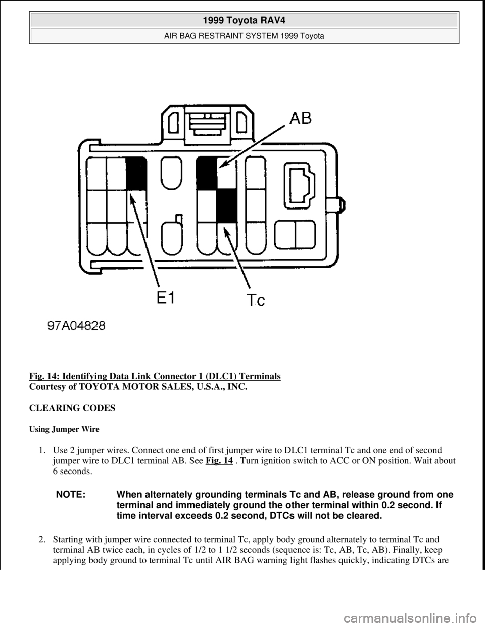
Fig. 14: Identifying Data Link Connector 1 (DLC1) Terminals
Courtesy of TOYOTA MOTOR SALES, U.S.A., INC.
CLEARING CODES
Using Jumper Wire
1. Use 2 jumper wires. Connect one end of first jumper wire to DLC1 terminal Tc and one end of second
jumper wire to DLC1 terminal AB. See Fig. 14
. Turn ignition switch to ACC or ON position. Wait about
6 seconds.
2. Starting with jumper wire connected to terminal Tc, apply body ground alternately to terminal Tc and
terminal AB twice each, in cycles of 1/2 to 1 1/2 seconds (sequence is: Tc, AB, Tc, AB). Finally, keep
appl
ying body ground to terminal Tc until AIR BAG warning light flashes quickly, indicating DTCs are
NOTE: When alternately grounding terminals Tc and AB, release ground from one
terminal and immediately ground the other terminal within 0.2 second. If
time interval exceeds 0.2 second, DTCs will not be cleared.
1999 Toyota RAV4
AIR BAG RESTRAINT SYSTEM 1999 Toyota
Microsoft
Sunday, November 22, 2009 10:33:23 AMPage 22 © 2005 Mitchell Repair Information Company, LLC.
Page 88 of 1632
Fig. 15: Releasing Shorting Spring
Courtesy of TOYOTA MOTOR SALES, U.S.A., INC.
DIAGNOSTIC TESTS
AIR BAG WARNING LIGHT DOES NOT ILLUMINATE
Description
AIR BAG warning light is located in instrument cluster. When air bag system is normal, AIR BAG warning
light illuminates for about 6 seconds after ignition switch is turned from LOCK to ACC or ON position, and
turns off automatically. If a malfunction is present in air bag system, AIR BAG warning light illuminates to
inform operator of malfunction. When Data Link Connector 1 (DLC1) terminals Tc and E1 are connected
together, a Diagnostic Trouble Code (DTC) is displayed by flashing AIR BAG warning light.
Diagnostic Procedure
1. Remove SRS-B fuse and check continuity across fuse blades. SRS-B fuse is located in instrument panel
fuse block under left side of instrument panel. If fuse is faulty, go to step 4). If fuse is okay, reinstall fuse
and go to next step.
2. Disable air bag system. See DISABLING SYSTEM
under DISABLING & ACTIVATING AIR BAG
SYSTEM. Reconnect negative battery cable. Turn ignition switch to ACC or ON position. Measure
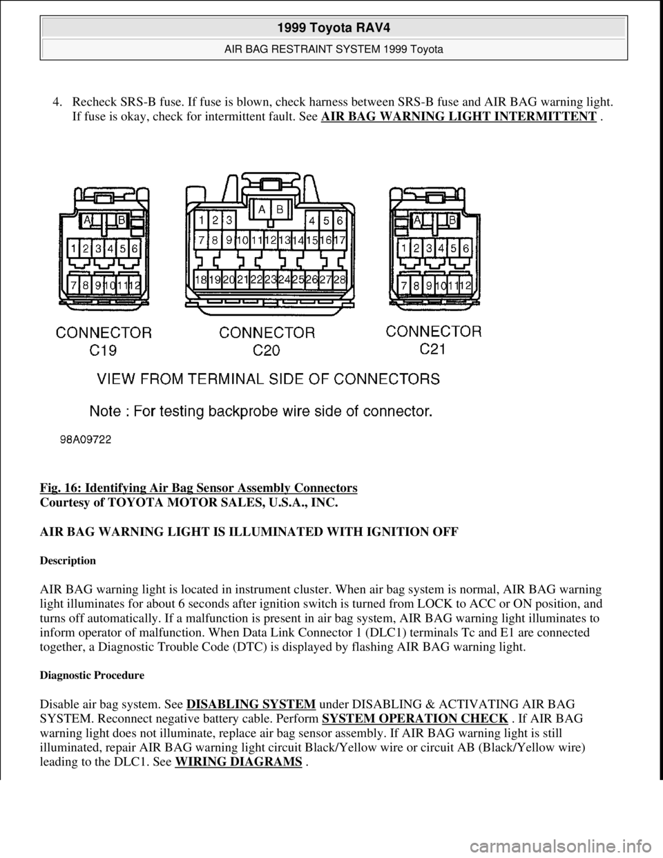
voltage between ground and harness side of air bag sensor assembly connector C20, terminal No. 3
(circuit LA, Black/Yellow wire). See Fig. 16
. If 10-14 volts is not present, repair AIR BAG warning
light bulb or circuit. If 10-14 volts is present, go to next step.
3. Turn ignition switch to LOCK position. Disconnect negative battery cable. Reconnect 3 air bag sensor
assembly connectors. Leave air bag modules, pretensioners and front air bag sensors disconnected.
Reconnect negative battery cable and wait at least 2 seconds. Turn ignition switch to ACC or ON
position. If AIR BAG warning light illuminates, system operation is normal. If AIR BAG warning light
does not come on, check for poor connection at air bag sensor assembly connector C20, terminal No. 3
(Black/Yellow wire). If connection is oka
y, replace air bag sensor assembly. WARNING:Failure to follow service precautions may result in air bag deployment and
personal injury. See SERVICE PRECAUTIONS
. After component
replacement, check system operation. See SYSTEM OPERATION CHECK
.
CAUTION: Ensure ignition switch is in LOCK position before disconnecting or
connecting negative battery cable. If ignition switch is in ACC or ON
position when negative battery cable is disconnected or connected, air
bag sensor may be damaged. To prevent damage to connector terminals,
DO NOT probe terminal ends. Instead, backprobe terminals (probe
terminal where wire enters harness connector).
NOTE: In the following tests, the term squib connector and module connector may be
used interchangeably.
1999 Toyota RAV4
AIR BAG RESTRAINT SYSTEM 1999 Toyota
Microsoft
Sunday, November 22, 2009 10:33:23 AMPage 25 © 2005 Mitchell Repair Information Company, LLC.
Page 89 of 1632
4. Recheck SRS-B fuse. If fuse is blown, check harness between SRS-B fuse and AIR BAG warning light.
If fuse is okay, check for intermittent fault. See AIR BAG WARNING LIGHT INTERMITTENT
.
Fig. 16: Identifying Air Bag Sensor Assembly Connectors
Courtesy of TOYOTA MOTOR SALES, U.S.A., INC.
AIR BAG WARNING LIGHT IS ILLUMINATED WITH IGNITION OFF
Description
AIR BAG warning light is located in instrument cluster. When air bag system is normal, AIR BAG warning
light illuminates for about 6 seconds after ignition switch is turned from LOCK to ACC or ON position, and
turns off automatically. If a malfunction is present in air bag system, AIR BAG warning light illuminates to
inform operator of malfunction. When Data Link Connector 1 (DLC1) terminals Tc and E1 are connected
together, a Diagnostic Trouble Code (DTC) is displayed by flashing AIR BAG warning light.
Diagnostic Procedure
Disable air bag system. See DISABLING SYSTEM under DISABLING & ACTIVATING AIR BAG
SYSTEM. Reconnect negative battery cable. Perform SYSTEM OPERATION CHECK
. If AIR BAG
warning light does not illuminate, replace air bag sensor assembly. If AIR BAG warning light is still
illuminated, repair AIR BAG warning light circuit Black/Yellow wire or circuit AB (Black/Yellow wire)
leadin
g to the DLC1. See WIRING DIAGRAMS.
1999 Toyota RAV4
AIR BAG RESTRAINT SYSTEM 1999 Toyota
Microsoft
Sunday, November 22, 2009 10:33:23 AMPage 26 © 2005 Mitchell Repair Information Company, LLC.
Page 90 of 1632
AIR BAG WARNING LIGHT INTERMITTENT
If AIR BAG warning light comes on intermittently, perform following tests to simulate driving conditions. If
problem cannot be found, replace all components including wiring harness.
Wiggle-test wiring harness.
Apply heat to components with a hair dryer.
Spray water onto entire vehicle (not directly onto electrical components) to simulate humidity.
DTCS NOT DISPLAYED
Description
When DLC1 terminals Tc and E1 are connected together, air bag sensor assembly is set in Diagnostic Trouble
Code (DTC) output mode. DTC is displayed by flashing AIR BAG warning light.
Diagnostic Procedure
1. Turn ignition switch from LOCK to ACC or ON position. If AIR BAG warning light does not illuminate
for about 6 seconds, repair AIR BAG warning light circuit. See WIRING DIAGRAMS
. If AIR BAG
warning light illuminates for about 6 seconds, go to next step.
2. Measure voltage between DLC1 terminals Tc and E1. See Fig. 14
. If 10-14 volts is present, go to step 4).
If 10-14 volts is not present, go to next step.
3. Measure voltage between ground and DLC1 terminal Tc. If 10-14 volts is present, repair harness between
ground and DLC1 terminal E1. See WIRING DIAGRAMS
. If 10-14 volts is not present, go to next
step.
4. Turn ignition switch to LOCK position. Disconnect negative battery cable and wait at least 90 seconds.
Access and disconnect air bag sensor assembly connector C20 (center connector). See AIR BAG
SENSOR ASSEMBLY under REMOVAL & INSTALLATION
. Connect one end of jumper wire to
harness side of air bag sensor assembly connector C20, terminal No. 19 (Circuit Tc, Pink/Black wire).
See Fig. 16
. Leave other end of jumper wire disconnected. Reconnect air bag sensor assembly connector
with jumper wire connected. Connect negative battery cable and turn ignition switch to ACC or ON
position. Wait at least 20 seconds. Connect unconnected end of jumper wire to ground. If AIR BAG
warning light does not illuminate, replace air bag sensor assembly. If AIR BAG warning light illuminates,
check Pink/Black wire between air bag sensor assembly and DLC1.
DTCS CONTINUOUSLY DISPLAYED
Description
NOTE: Use following procedure if DTCs are not displayed or air bag warning light stays
on when jumper wire is connected between terminals Tc and E1 of DLC1.
NOTE: Use following procedure if DTCs are displayed without connecting jumper wire
between terminals Tc and E1 of DLC1.
1999 Toyota RAV4
AIR BAG RESTRAINT SYSTEM 1999 Toyota
Microsoft
Sunday, November 22, 2009 10:33:23 AMPage 27 © 2005 Mitchell Repair Information Company, LLC.
Page 91 of 1632
When DLC1 terminals Tc and E1 are connected together, air bag sensor assembly is set in Diagnostic Trouble
Code (DTC) output mode. DTC is displayed by flashing AIR BAG warning light.
Diagnostic Procedure
1. Turn ignition switch to LOCK position. Disconnect negative battery cable. Wait at least 90 seconds.
Access and disconnect air bag sensor assembly connector C20 (center connector). See AIR BAG
SENSOR ASSEMBLY under REMOVAL & INSTALLATION
.
2. Measure resistance between ground and air bag sensor assembly connector C20, terminal No. 19 (circuit
Tc, Pink/Black wire). See Fig. 16
. If resistance is more than one megohm, replace air bag sensor
assembly. If resistance is less than one megohm, replace harness and connector.
SOURCE VOLTAGE DROP
Description
The air bag sensor assembly is equipped with a voltage-increase circuit to allow system operation in case source
(battery) voltage drops below minimum. When battery voltage drops, voltage-increase circuit functions to
increase voltage of air bag system to normal voltage.
The malfunction display for this circuit is different from other air bag system circuits. When source voltage
drop is detected and no other DTCs are present, the AIR BAG warning light remains illuminated constantly.
Source voltage drop is not recorded in air bag sensor assembly as a malfunction, and when source voltage
returns to normal, AIR BAG warning light will turn off.
Diagnostic Procedure
1. Turn ignition switch to LOCK position. Disable air bag system. See DISABLING SYSTEM under
DISABLING AND ACTIVATING AIR BAG SYSTEM. Reconnect negative battery cable.
2. Turn ignition switch to ON position. Turn on electrical accessories (defogger, wipers, headlights, blower
motor, etc.). Measure voltage between ground and air bag sensor assembly connector C20, terminals No.
5 (circuit IG2, Black/Orange wire) and No. 6 (circuit ACC, Gray wire). See Fig. 16
. Turn electrical
accessories off. If voltage is 10-14 volts, go to next step. If voltage is not 10-14 volts, check harness
between battery and air bag sensor assembly and check battery and charging system.
3. Turn ignition switch to LOCK position. Activate air bag system. See ACTIVATING SYSTEM
under
DISABLING & ACTIVATING AIR BAG SYSTEM. Turn ignition switch to ON position. Turn on
electrical accessories again. If AIR BAG warning light goes out, system operation is normal at this time.
If AIR BAG warning light does not go out, check for DTCs. See RETRIEVING CODES
under
DIAGNOSIS & TESTING. If DTC is displayed, go to appropriate DTC. If a normal code is displayed (2
flashes per second), replace air bag sensor assembly.
DTC 11/B0102: DRIVER-SIDE AIR BAG SQUIB CIRCUIT SHORT TO GROUND
Description
The driver-side air bag squib circuit consists of the air bag sensor assembly, spiral cable and driver-side air bag
module. The squib causes drive
r-side air bag to deploy when all deployment conditions are satisfied.
1999 Toyota RAV4
AIR BAG RESTRAINT SYSTEM 1999 Toyota
Microsoft
Sunday, November 22, 2009 10:33:23 AMPage 28 © 2005 Mitchell Repair Information Company, LLC.
Page 92 of 1632
Possible Causes
DTC 11/B0102 could be caused by a short to ground in squib circuit, squib malfunction, spiral cable
malfunction or air bag sensor assembly malfunction.
Diagnostic Procedure
1. Disable air bag system. See DISABLING SYSTEM under DISABLING & ACTIVATING AIR BAG
SYSTEM.
2. Measure resistance between ground and terminal D+ (Yellow/Black wire) of spiral cable side of upper
spiral cable connector. See WIRING DIAGRAMS
. If resistance is more than one megohm, go to next
step. If resistance is less than one megohm, go to step 5).
3. Reconnect air bag sensor assembly connector C20 (center connector). Connect jumper wire between
terminal D+ (Yellow/Black wire) and terminal D- (Yellow wire) of spiral cable side of upper spiral cable
connector. Connect negative battery cable. Wait at least 2 seconds. Turn ignition switch to ACC or ON
position. Wait at least 20 seconds. Clear DTCs. See CLEARING CODES
under DIAGNOSIS &
TESTING. Turn ignition switch to LOCK position. Wait at least 20 seconds. Turn ignition switch to ACC
or ON position. Wait at least 20 seconds. Retrieve DTCs. See RETRIEVING CODES
under
DIAGNOSIS & TESTING. If DTC 11/B0102 is displayed, replace air bag sensor assembly. If DTC
11/B0102 is not displayed, go to next step.
4. Turn ignition switch to LOCK position. Disconnect negative battery cable. Wait at least 90 seconds.
Reconnect upper spiral cable connector (to driver-side air bag module). Reconnect negative battery cable.
Wait at least 2 seconds. Turn ignition switch to ACC or ON position. Wait at least 20 seconds. Clear
DTCs. See CLEARING CODES
under DIAGNOSIS & TESTING. Turn ignition switch to LOCK
position. Wait at least 20 seconds. Turn ignition switch to ACC or ON position. Wait at least 20 seconds.
Retrieve codes. See RETRIEVING CODES
under DIAGNOSIS & TESTING. If DTC 11/B0102 is
displayed, replace driver-side air bag module. If DTC 11/B0102 is not displayed, system is functioning
properly at this time. Check for intermittent fault. See AIR BAG WARNING LIGHT
INTERMITTENT .
5. Disconnect spiral cable lower connector. Measure resistance between ground and terminal D+
(Yellow/Black wire) of spiral cable side of upper spiral cable connector. If resistance is more than one
megohm, repair or replace wiring harness or connector between spiral cable and air bag sensor assembly.
If resistance is less than one megohm, replace spiral cable.
DTC 12/B0103: DRIVER-SIDE AIR BAG SQUIB CIRCUIT SHORT TO BATTERY
Description
The driver-side air bag squib circuit consists of the air bag sensor assembly, spiral cable and driver-side air bag
module. The squib causes driver-side air bag to deploy when all deployment conditions are satisfied.
Possible Causes
DTC 12/B0103 could be caused by a short to battery in squib circuit, squib malfunction, spiral cable NOTE: During testing, if DTCs other than DTC 11/B0102 are displayed, disregard them.
1999 Toyota RAV4
AIR BAG RESTRAINT SYSTEM 1999 Toyota
Microsoft
Sunday, November 22, 2009 10:33:23 AMPage 29 © 2005 Mitchell Repair Information Company, LLC.
Page 93 of 1632
malfunction or air bag sensor assembly malfunction.
Diagnostic Procedure
1. Disable air bag system. See DISABLING SYSTEM under DISABLING & ACTIVATING AIR BAG
SYSTEM. Connect negative battery cable.
2. Measure voltage between ground and D+ (Yellow/Black wire) terminal of spiral cable side of upper spiral
cable connector. If voltage is zero volt, go to next step. If voltage more than zero volt, go to step 5).
3. Disconnect negative battery cable. Reconnect air bag sensor assembly connector C20 (center connector).
Connect jumper wire between terminal D+ (Yellow/Black wire) and terminal D- (Yellow wire) of spiral
cable side of upper spiral cable connector. Connect negative battery cable. Wait at least 2 seconds. Turn
ignition switch to ACC or ON position. Wait at least 20 seconds. Clear DTCs. See CLEARING CODES
under DIAGNOSIS & TESTING. Turn ignition switch to LOCK position. Wait at least 20 seconds. Turn
ignition switch to ACC or ON position. Wait at least 20 seconds. Retrieve codes. See RETRIEVING
CODES under DIAGNOSIS & TESTING. If DTC 12/B0103 is displayed, replace air bag sensor
assembly. If DTC 12/B0103 is not displayed, go to next step.
4. Turn ignition switch to LOCK position. Disconnect negative battery cable. Wait at least 90 seconds.
Reconnect upper spiral cable connector (to driver-side air bag module). Reconnect negative battery cable.
Wait at least 2 seconds. Turn ignition switch to ACC or ON position. Wait at least 20 seconds. Clear
DTCs. See CLEARING CODES
under DIAGNOSIS & TESTING. Turn ignition switch to LOCK
position. Wait at least 20 seconds. Turn ignition switch to ACC or ON position. Wait at least 20 seconds.
Retrieve codes. See RETRIEVING CODES
under DIAGNOSIS & TESTING. If DTC 12/B0103 is
displayed, replace driver-side air bag module. If DTC 12/B0103 is not displayed, system is functioning
properly at this time. Check for intermittent fault. See AIR BAG WARNING LIGHT
INTERMITTENT .
5. Disconnect spiral cable lower connector. Measure voltage between ground and terminal D+
(Yellow/Black wire) of spiral cable side of upper spiral cable connector. If voltage is zero volt, repair or
replace wiring harness or connector between spiral cable and air bag sensor assembly. If voltage is more
than zero volt, replace spiral cable.
DTC 13/B0100: SHORT IN DRIVER-SIDE AIR BAG MODULE SQUIB CIRCUIT
Description
The driver-side air bag squib circuit consists of the air bag sensor assembly, spiral cable and driver-side air bag
module. The squib causes driver-side air bag to deploy when all deployment conditions are satisfied.
Possible Causes
DTC 13/B0100 could be caused by a short between D+ (Yellow/Black wire) and D- (Yellow wire) in squib
circuit, squib malfunction, spiral cable malfunction or air bag sensor assembly malfunction. NOTE: During testing, if DTCs other than DTC 12/B0103 are displayed, disregard them.
NOTE: During testing, if DTCs other than DTC 13/B0100 are displayed, disregard them.
1999 Toyota RAV4
AIR BAG RESTRAINT SYSTEM 1999 Toyota
Microsoft
Sunday, November 22, 2009 10:33:23 AMPage 30 © 2005 Mitchell Repair Information Company, LLC.