light TOYOTA RAV4 1996 Service Owner's Manual
[x] Cancel search | Manufacturer: TOYOTA, Model Year: 1996, Model line: RAV4, Model: TOYOTA RAV4 1996Pages: 1632, PDF Size: 41.64 MB
Page 53 of 1632
light is okay, the malfunction is now corrected. If light is not okay, check terminal LA of air bag sensor
assembly. If terminal is okay, replace air bag sensor assembly.
5. If new fuse burns out again, check harness between SRS fuse and SRS warning light. If fuse is not burned
out check for intermittent fault. See AIR BAG WARNING LIGHT INTERMITTENT
under
DIAGNOSIS.
AIR BAG WARNING LIGHT STAYS ON WITH IGNITION OFF
Disable SRS. See DISABLING & ACTIVATING AIR BAG SYSTEM
. Disconnect air bag sensor connector
(s). Reconnect negative battery cable. If air bag warning light is off, replace air bag sensor. If air bag warning
light is still on, repair warning light circuit or AB circuit leading to DLC. See Fig. 12
.
AIR BAG WARNING LIGHT INTERMITTENT
If air bag warning light comes on intermittently, perform the following tests to simulate driving conditions:
Wiggle-test wiring harness.
Using a hair dryer, apply heat to components.
Spray water onto entire vehicle (not directly onto electrical components) to simulate humidity.
If problem cannot be found, replace all components including wiring harness.
CODE(S) NOT DISPLAYED
1. Turn ignition switch from LOCK to ACC or ON position. If air bag warning light does not come on,
repair air bag warning light circuit. If air bag warning light comes on, go to next step.
2. Turn ignition to ACC or ON. Measure voltage between terminals Tc and E1 of DLC. See Fig. 12
. If
battery voltage is present, go to step 4). If battery voltage is not present go to next step.
3. Measure voltage between body ground and terminal Tc of DLC. If battery voltage is present, repair
harness between body ground and terminal E1 of DLC. If battery voltage is not present, go to next step.
4. Turn ignition to LOCK. Disconnect negative battery cable. wait at least 90 seconds. Disconnect air bag
sensor assembly connector. Connect a jumper wire between body ground and terminal Tc from back side.
See Fig. 13
. If air bag warning light does not come on, replace air bag sensor. If air bag warning light
comes on, check wiring harness between air bag sensor and DLC.
CODE(S) CONTINUOUSLY DISPLAYED
Disable SRS. See DISABLING & ACTIVATING AIR BAG SYSTEM
. Disconnect air bag sensor connector
NOTE: Use the following procedure if code(s) are not displayed or air bag warning light
stays on when jumper wire is connected between terminals Tc and E1 of DLC
connector.
NOTE: Use the following procedure if code(s) are displayed without connecting jumper
wire between terminals Tc and E1 of DLC connector.
1996 Toyota 4Runner
AIR BAG RESTRAINT SYSTEM 1996 ACCESSORIES/SAFETY EQUIPMENT Toyota Air Bag Restraint System
Microsoft
Tuesday, August 18, 2009 7:33:32 PMPage 19 © 2005 Mitchell Repair Information Company, LLC.
Page 56 of 1632
3. With squib circuit connector disconnected, insert paper into female terminal, sliding it under shorting bar
spring. This lifts the spring, breaking the circuit and allowing the test procedure to be performed as
specified.
TESTING - DIAGNOSTIC
NO CODES - SOURCE VOLTAGE DROP
1. Disconnect negative battery cable. Wait at least 90 seconds. Remove steering wheel pad. See
STEERING WHEEL PAD & SPIRAL CABLE
under REMOVAL & INSTALLATION. Disconnect
passenger-side air bag harness connector, accessible through finish plate in glove box. See Fig. 2
.
Disconnect air bag sensor assembly connector.
2. Reconnect negative battery cable. Turn ignition switch to ON position. Measure voltage between ground
and terminals IG2 and ACC of air bag sensor connector. See Fig. 13
. Operate electrical components
(defogger, wiper, headlights, heater blower, etc.). If voltage is 8-14 volts, go to next step. If voltage is not
8-14 volts, check harness between battery and air bag sensor assembly and check battery and charging
system.
3. Turn ignition switch to LOCK position. Connect steering wheel pad connector. Connect passenger-side
air bag connector. Turn ignition switch to ON position. Operate electrical components as in step 2) and
check that SRS warning light goes off. If light does not go off, check diagnostic trouble code and go to
appropriate CODE under TESTING - DIAGNOSTIC. If a normal code is output, replace air bag sensor
assembly. If warning light goes off, no problem detected at this time.
CODE 11
1. Disconnect negative battery cable. Wait at least 90 seconds. Remove steering wheel pad. See
STEERING WHEEL PAD & SPIRAL CABLE
under REMOVAL & INSTALLATION. Disconnect
passenger-side air bag harness connector, accessible through finish plate in glove box. See Fig. 2
.
Disconnect air bag sensor assembly connector.
2. Measure resistance on spiral cable side of connector between spiral cable and steering wheel pad between
D+, D- and ground. If resistance is 1000 ohms or more, go to next step. If resistance is less than 1000
ohms, go to step 7).
3. Measure resistance on air ba
g sensor assembly side of connector between air bag sensor and passenger- WARNING:Paper must not be thicker than male terminal. If paper is thicker,
connector terminal may be damaged, possible resulting in system
fault.
NOTE: Use Diagnosis Check Wiring (09843-18020) when connecting jumper wire
between terminals of DLC. Spiral cable upper connector is same as steering
wheel pad (squib) connector. Spiral cable lower connector (located under
steering column) connects the harness between spiral cable and center air bag
sensor.
NOTE: During testing, if codes other than Code 11 are displayed, disregard them.
1996 Toyota 4Runner
AIR BAG RESTRAINT SYSTEM 1996 ACCESSORIES/SAFETY EQUIPMENT Toyota Air Bag Restraint System
Microsoft
Tuesday, August 18, 2009 7:33:32 PMPage 22 © 2005 Mitchell Repair Information Company, LLC.
Page 59 of 1632
resistance is less than one ohm, no problem detected at this time. If resistance is more than one ohm,
replace harness or connector between air bag sensor and spiral cable.
CODE 31
1. Disconnect negative battery cable. Wait at least 90 seconds. Remove steering wheel pad. See
STEERING WHEEL PAD & SPIRAL CABLE
under REMOVAL & INSTALLATION. Disconnect
passenger-side air bag connector, accessible through finish plate inside glove box. See Fig. 2
. Disconnect
air bag sensor assembly connector.
2. Turn ignition switch to ON position. Measure voltage between terminals IG2 and ACC of air bag sensor
assembly and ground. If voltage is less than 16 Volts, go to next step. If voltage is more than 16 volts,
check battery and charging system.
3. Clear malfunction code. Turn ignition switch to LOCK position. Wait at least 20 seconds. Turn ignition
switch to ACC or ON position. Wait at least 20 seconds. Repeat these steps at least 5 times. Using
Diagnosis Wire (09843-18020), connect terminals Tc and E1 of DLC1. Check DTC. If CODE 31 is
output, replace air bag sensor assembly. If CODE 31 is not output, check for intermittent fault. See AIR
BAG WARNING LIGHT INTERMITTENT under DIAGNOSIS.
CODE 54
1. Disconnect negative battery cable. Wait at least 90 seconds. Remove steering wheel pad. See
STEERING WHEEL PAD & SPIRAL CABLE
under REMOVAL & INSTALLATION. Disconnect
passenger-side air bag connector, accessible through finish plate inside glove box. See Fig. 2
. Disconnect
air bag sensor assembly connector.
2. Using a jumper wire, connect P+ and P- of air bag sensor connector. Measure resistance between
terminals of passenger-side air bag connector. If resistance is less than one ohm, go to next step. If
resistance is more than one ohm, replace harness or connector between air bag sensor assembly and
passenger-side air bag assembly.
3. Connect connector to center air bag sensor assembly. Using a jumper wire, connect P+ and P- terminals
(on center air bag sensor assembly side of connector between center air bag sensor assembly) and
passenger-side air bag assembly. Connect negative battery cable and wait 20 seconds. Turn ignition
switch to ACC or ON position. Wait at least 20 seconds. Clear malfunction codes. Turn ignition switch to
LOCK position. Wait at least 20 seconds. Turn ignition switch to ACC or ON position. Wait for at least
20 seconds. Using Diagnosis Wire (09843-18020), check for DTC 54. If DTC 54 is output, replace air
bag sensor assembly. If DTC 54 is not output, go to next step.
4. Turn ignition switch to LOCK position. Disconnect negative battery cable. Wait at least 90 seconds.
Connect passenger-side air bag assembly connector. Connect negative battery cable. Wait 2 seconds.
Turn ignition switch to ACC or ON position. Wait at least 20 seconds. Clear malfunction codes. Turn
ignition switch to LOCK position. Wait at least 20 seconds. Turn ignition switch to ACC or ON position.
Wait at least 20 seconds. Using Diagnosis Wire (09843-18020), check for DTC 54. If DTC 54 is output,
replace passen
ger-side air bag assembly. If DTC 54 is not output, the malfunction is now normal. NOTE: During testing, if codes other than Code 14 are displayed, disregard them.
NOTE: During testing, if codes other than Code 54 are displayed, disregard them.
1996 Toyota 4Runner
AIR BAG RESTRAINT SYSTEM 1996 ACCESSORIES/SAFETY EQUIPMENT Toyota Air Bag Restraint System
Microsoft
Tuesday, August 18, 2009 7:33:32 PMPage 25 © 2005 Mitchell Repair Information Company, LLC.
Page 60 of 1632
AIR BAG SENSOR CONNECTOR TERMINAL IDENTIFICATION
POST-COLLISION AIR BAG SAFETY INSPECTION
POST-COLLISION AIR BAG SAFETY INSPECTION
WIRE REPAIR
TORQUE SPECIFICATIONS
TORQUE SPECIFICATIONS
TerminalCircuit
"A" (L1)Shorting Bar
"B" (L2)Shorting Bar
1 (P-)Squib "-" Passenger-Side
2 (P+)Squib "+" Passenger-Side
3 (D+)Squib "+" Driver-Side
4 (D-)Squib "-" Driver-Side
5 (E1)Ground
6 (E2)Ground
7 (Tc)Diagnosis
8 (LA)Air Bag Warning Light
9 (IG2)Power Source (IGN Fuse)
10 (ACC)Power Source (CIG Fuse)
ActionComponents
Replace After DeploymentAir Bag Module(s), Air Bag Sensor Assembly
Inspect & If Damaged, Replace Component (Even
If Air Bag Did Not Deploy)Glove Compartment Door, Instrument Panel,
Instrument Panel Reinforcement, Spiral Cable
Steering Wheel, Wiring Harness & Connectors
CommentsIf any components are damaged or bent, they must
be replaced.
WARNING:No part of the SRS system or harnesses can be repaired. If wiring harness
is damaged, replace complete wiring harness assembly.
ApplicationFt. Lbs. (N.m)
Air Bag Sensor Screw15 (21)
Instrument Panel Reinforcement14 (19)
Passenger-Side Air Bag Bolt15 (21)
Steering Wheel Nut26 (35)
INCH Lbs. (N.m)
Steering Wheel Pad Torx Screw80 (9)
1996 Toyota 4Runner
AIR BAG RESTRAINT SYSTEM 1996 ACCESSORIES/SAFETY EQUIPMENT Toyota Air Bag Restraint System
Microsoft
Tuesday, August 18, 2009 7:33:32 PMPage 26 © 2005 Mitchell Repair Information Company, LLC.
Page 64 of 1632
AIR BAG RESTRAINT SYSTEM
1999 Toyota
DESCRIPTION & OPERATION
Supplemental Restraint System (SRS), also known as air bag system, is designed to provide increased accident
protection for driver and passenger by deploying air bags in a front-end collision. The air bag system is
designed to be used in conjunction with 3-point safety belts.
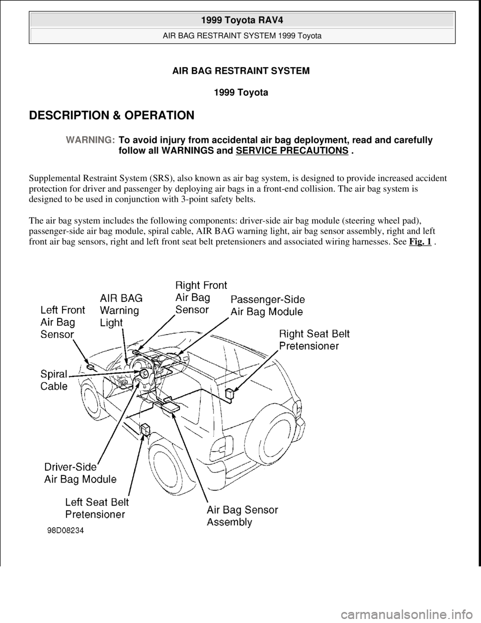
The air bag system includes the following components: driver-side air bag module (steering wheel pad),
passenger-side air bag module, spiral cable, AIR BAG warning light, air bag sensor assembly, right and left
front air bag sensors, right and left front seat belt pretensioners and associated wiring harnesses. See Fig. 1
. WARNING:To avoid injury from accidental air bag deployment, read and carefully
follow all WARNINGS and SERVICE PRECAUTIONS
.
1999 Toyota RAV4
AIR BAG RESTRAINT SYSTEM 1999 Toyota
1999 Toyota RAV4
AIR BAG RESTRAINT SYSTEM 1999 Toyota
Microsoft
Sunday, November 22, 2009 10:33:22 AMPage 1 © 2005 Mitchell Repair Information Company, LLC.
Microsoft
Sunday, November 22, 2009 10:33:26 AMPage 1 © 2005 Mitchell Repair Information Company, LLC.
Page 66 of 1632
may allow air bag to deploy until 90 seconds after disconnecting negative battery cable.
If vehicle was in a minor collision but air bags did not deploy, inspect all system components for any sign
of damage, and replace as necessary.
Never use air bag system components from another vehicle. Replace air bag system components with new
parts.
Remove air bag sensor assembly if repairing the vehicle requires impacting (shocking) the vehicle.
Air bag sensor assembly contains mercury. After replacement, DO NOT destroy old part. When
scrapping vehicle or replacing air bag sensor assembly, remove air bag sensor assembly and dispose of it
as toxic waste.
Never disassemble and repair air bag sensor assembly, front air bag sensors, passenger-side or driver-side
air bag modules or seat belt pretensioners.
Replace dropped, cracked, dented or otherwise damaged components.
DO NOT expose air bag sensor assembly, front air bag sensors or air bag modules directly to heat or
flame.
When diagnosing electrical circuits, use a volt/ohm meter with high impedance (10,000 ohms minimum).
Information labels are attached to air bag components. Follow all notices on labels.
After work on air bag system is complete, check AIR BAG warning light to ensure system is functioning
properly. See SYSTEM OPERATION CHECK
.
Always wear safety glasses when servicing or handling an air bag.
When placing a live air bag on a bench or other surface, always face air bag and trim cover up and away
from surface. This will reduce motion of module if it is accidentally deployed.
After deployment, air bag surface may contain deposits of sodium hydroxide, which irritates skin. Always
wear safety glasses, rubber gloves, and long-sleeved shirt during clean-up. After clean-up, wash hands
using mild soap and water.
Carry a live air bag module with trim cover (air bag) pointed away from your body to minimize injury in
case accidental deployment.
If air bag system is not fully functional for any reason, vehicle should not be driven until system is
repaired and again becomes operational. DO NOT remove bulbs, modules, sensors or other components,
or in any way disable system from operating normally. If air bag system is not functional, park vehicle
until it is repaired and functions properly.
ADJUSTMENTS
SPIRAL CABLE
Ensure front wheels are in straight-ahead position. Turn spiral cable counterclockwise until it becomes difficult
to turn. Turn spiral cable clockwise about 2 1/2 turns to align match marks. See Fig. 2
. Install steering wheel.
1999 Toyota RAV4
AIR BAG RESTRAINT SYSTEM 1999 Toyota
Microsoft
Sunday, November 22, 2009 10:33:22 AMPage 3 © 2005 Mitchell Repair Information Company, LLC.
Page 76 of 1632
REMOVAL & INSTALLATION
AIR BAG SENSOR ASSEMBLY
Removal & Installation
1. Before proceeding, see SERVICE PRECAUTIONS . Air bag sensor assembly is located on the floor
inside center console box. See Fig. 10
. Turn ignition switch to LOCK position. Disconnect negative
battery cable. Wait at least 90 seconds.
2. Remove shift lever and boot. Ash tray and console box hole cover. Remove console box. Remove 4 Torx
screws retaining air bag sensor assembly. Remove air bag sensor assembly.
3. To install, reverse removal procedure. Tighten air bag sensor assembly Torx screws to specification. See
TORQUE SPECIFICATIONS
. Check AIR BAG warning light to ensure system is functioning
properl
y. See SYSTEM OPERATION CHECK. WARNING:Failure to follow service precautions may result in air bag deployment and
personal injury. See SERVICE PRECAUTIONS
. After component
replacement, check system operation. See SYSTEM OPERATION CHECK
.
1999 Toyota RAV4
AIR BAG RESTRAINT SYSTEM 1999 Toyota
Microsoft
Sunday, November 22, 2009 10:33:22 AMPage 13 © 2005 Mitchell Repair Information Company, LLC.
Page 78 of 1632
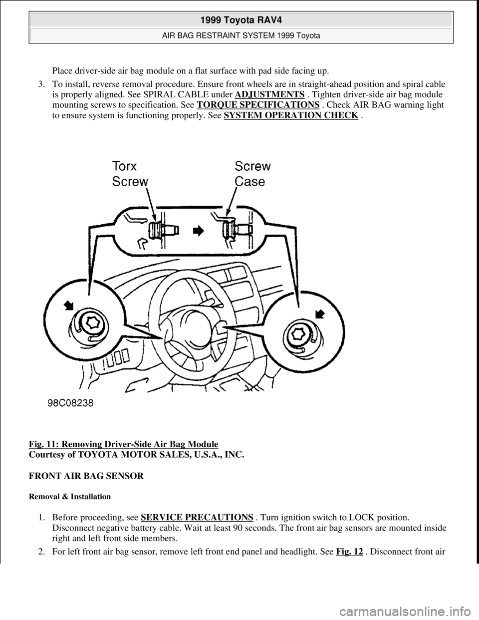
Place driver-side air bag module on a flat surface with pad side facing up.
3. To install, reverse removal procedure. Ensure front wheels are in straight-ahead position and spiral cable
is properly aligned. See SPIRAL CABLE under ADJUSTMENTS
. Tighten driver-side air bag module
mounting screws to specification. See TORQUE SPECIFICATIONS
. Check AIR BAG warning light
to ensure system is functioning properly. See SYSTEM OPERATION CHECK
.
Fig. 11: Removing Driver
-Side Air Bag Module
Courtesy of TOYOTA MOTOR SALES, U.S.A., INC.
FRONT AIR BAG SENSOR
Removal & Installation
1. Before proceeding, see SERVICE PRECAUTIONS . Turn ignition switch to LOCK position.
Disconnect negative battery cable. Wait at least 90 seconds. The front air bag sensors are mounted inside
right and left front side members.
2. For left front air ba
g sensor, remove left front end panel and headlight. See Fig. 12 . Disconnect front air
1999 Toyota RAV4
AIR BAG RESTRAINT SYSTEM 1999 Toyota
Microsoft
Sunday, November 22, 2009 10:33:22 AMPage 15 © 2005 Mitchell Repair Information Company, LLC.
Page 79 of 1632
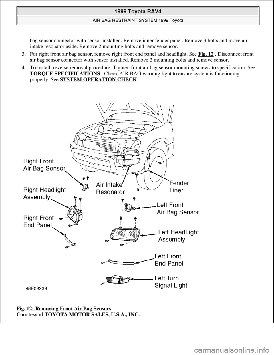
bag sensor connector with sensor installed. Remove inner fender panel. Remove 3 bolts and move air
intake resonator aside. Remove 2 mounting bolts and remove sensor.
3. For right front air bag sensor, remove right front end panel and headlight. See Fig. 12
. Disconnect front
air bag sensor connector with sensor installed. Remove 2 mounting bolts and remove sensor.
4. To install, reverse removal procedure. Tighten front air bag sensor mounting screws to specification. See
TORQUE SPECIFICATIONS
. Check AIR BAG warning light to ensure system is functioning
properly. See SYSTEM OPERATION CHECK
.
Fig. 12: Removing Front Air Bag Sensors
Courtesy of TOYOTA MOTOR SALES, U.S.A., INC.
1999 Toyota RAV4
AIR BAG RESTRAINT SYSTEM 1999 Toyota
Microsoft
Sunday, November 22, 2009 10:33:22 AMPage 16 © 2005 Mitchell Repair Information Company, LLC.
Page 80 of 1632
INSTRUMENT PANEL
Removal & Installation
1. Before proceeding, see SERVICE PRECAUTIONS . Turn ignition switch to LOCK position.
Disconnect negative battery cable. Wait at least 90 seconds.
2. Access and disconnect right and left seat belt pretensioner connectors. See SEAT BELT
PRETENSIONERS . Remove front door scuff plates and cowl side trim boards. See Fig. 13 . Remove
steering wheel. See STEERING WHEEL
. Remove steering column covers and cluster finish panel.
Remove instrument cluster. Remove hood lock release lever.
3. Remove lower finish panel and instrument panel lower insert. Remove No. 2 heater-to-register duct.
Remove steering column assembly. See STEERING COLUMN
. Remove 2 screws and center cluster
finish panel. Pull off heater control knobs and pry off heater control name plate. Pry off cluster instrument
panel, then remove 3 screws from heater control assembly. Disconnect connectors and remove cluster
instrument panel.
4. Disconnect control cables and remove heater control assembly. Remove radio assembly. Remove console
box. Tape tip of screwdriver and remove lower center cluster finish panel. Disconnect connectors.
Remove stereo opening cover. Remove glove box assembly. Remove side trim cover. Disconnect
remaining connectors and remove bolts, then remove instrument panel.
5. To install, reverse removal procedure. Tighten fasteners to specification. See TORQUE
SPECIFICATIONS . Check AIR BAG warning light to ensure system is functioning properly. See
SYSTEM OPERATION CHECK
.
1999 Toyota RAV4
AIR BAG RESTRAINT SYSTEM 1999 Toyota
Microsoft
Sunday, November 22, 2009 10:33:22 AMPage 17 © 2005 Mitchell Repair Information Company, LLC.