check engine TOYOTA RAV4 2006 Service Repair Manual
[x] Cancel search | Manufacturer: TOYOTA, Model Year: 2006, Model line: RAV4, Model: TOYOTA RAV4 2006Pages: 2000, PDF Size: 45.84 MB
Page 724 of 2000

2GR-FE ENGINE MECHANICAL – ENGINE UNITEM–87
EM
20. INSPECT INTAKE VALVE SEAT
(a) Apply a light coat of Prussian blue to the valve face.
(b) Lightly press the valve face against the valve seat.
(c) Check the valve face and valve seat by using the
following procedure.
(1) If Prussian blue appears around the entire
valve face, the valve face is concentric. If not,
replace the valve.
(2) If Prussian blue appears around the entire
valve seat, the guide and valve face are
concentric. If not, resurface the valve seat.
(3) Check that the valve seat contacts in the
middle of the valve face with the width between
1.1 and 1.5 mm (0.043 and 0.059 in.).
21. INSPECT EXHAUST VALVE SEAT
(a) Apply a light coat of Prussian blue to the valve face.
(b) Lightly press the valve face against the valve seat.
(c) Check the valve face and valve seat by using the
following procedure.
(1) If Prussian blue appears around the entire
valve face, the valve face is concentric. If not,
replace the valve.
(2) If Prussian blue appears around the entire
valve seat, the guide and valve face are
concentric. If not, resurface the valve seat.
(3) Check that the valve seat contacts in the
middle of the valve face with the width between
1.2 and 1.6 mm (0.047 and 0.063 in.).
22. INSPECT INNER COMPRESSION SPRING
(a) Using a vernier caliper, measure the free length of
the inner compression spring.
Standard free length:
45.46 mm (1.7898 in.)
If the free length is not as specified, replace the
spring.
(b) Using a steel square, measure the deviation of the
inner compression spring.
Maximum deviation:
1.0 mm (0.039 in.)
Maximum angle (reference):
2
If the deviation is greater than the maximum,
replace the spring.
A132152E01
A132152E01
A101392
A101393E02
Page 727 of 2000
EM–902GR-FE ENGINE MECHANICAL – ENGINE UNIT
EM
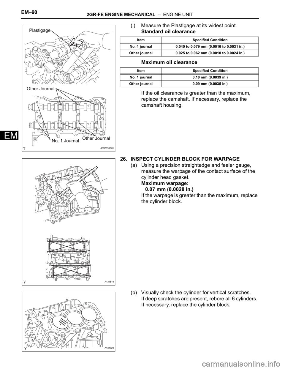
(l) Measure the Plastigage at its widest point.
Standard oil clearance
Maximum oil clearance
If the oil clearance is greater than the maximum,
replace the camshaft. If necessary, replace the
camshaft housing.
26. INSPECT CYLINDER BLOCK FOR WARPAGE
(a) Using a precision straightedge and feeler gauge,
measure the warpage of the contact surface of the
cylinder head gasket.
Maximum warpage:
0.07 mm (0.0028 in.)
If the warpage is greater than the maximum, replace
the cylinder block.
(b) Visually check the cylinder for vertical scratches.
If deep scratches are present, rebore all 6 cylinders.
If necessary, replace the cylinder block.
A132010E01
Item Specified Condition
No. 1 journal 0.040 to 0.079 mm (0.0016 to 0.0031 in.)
Other journal 0.025 to 0.062 mm (0.0010 to 0.0024 in.)
Item Specified Condition
No. 1 journal 0.10 mm (0.0039 in.)
Other journal 0.09 mm (0.0035 in.)
A131819
A131820
Page 730 of 2000
2GR-FE ENGINE MECHANICAL – ENGINE UNITEM–93
EM
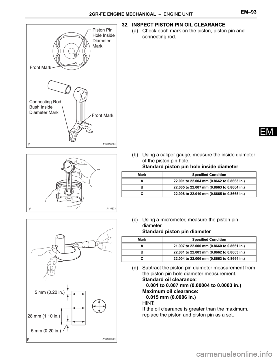
32. INSPECT PISTON PIN OIL CLEARANCE
(a) Check each mark on the piston, piston pin and
connecting rod.
(b) Using a caliper gauge, measure the inside diameter
of the piston pin hole.
Standard piston pin hole inside diameter
(c) Using a micrometer, measure the piston pin
diameter.
Standard piston pin diameter
(d) Subtract the piston pin diameter measurement from
the piston pin hole diameter measurement.
Standard oil clearance:
0.001 to 0.007 mm (0.00004 to 0.0003 in.)
Maximum oil clearance:
0.015 mm (0.0006 in.)
HINT:
If the oil clearance is greater than the maximum,
replace the piston and piston pin as a set.
A131950E01
A131823
Mark Specified Condition
A 22.001 to 22.004 mm (0.8662 to 0.8663 in.)
B 22.005 to 22.007 mm (0.8663 to 0.8664 in.)
C 22.008 to 22.010 mm (0.8665 to 0.8665 in.)
A132060E01
Mark Specified Condition
A 21.997 to 22.000 mm (0.8660 to 0.8661 in.)
B 22.001 to 22.003 mm (0.8662 to 0.8663 in.)
C 22.004 to 22.006 mm (0.8663 to 0.8664 in.)
Page 731 of 2000
EM–942GR-FE ENGINE MECHANICAL – ENGINE UNIT
EM
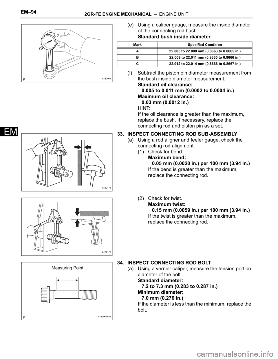
(e) Using a caliper gauge, measure the inside diameter
of the connecting rod bush.
Standard bush inside diameter
(f) Subtract the piston pin diameter measurement from
the bush inside diameter measurement.
Standard oil clearance:
0.005 to 0.011 mm (0.0002 to 0.0004 in.)
Maximum oil clearance:
0.03 mm (0.0012 in.)
HINT:
If the oil clearance is greater than the maximum,
replace the bush. If necessary, replace the
connecting rod and piston pin as a set.
33. INSPECT CONNECTING ROD SUB-ASSEMBLY
(a) Using a rod aligner and feeler gauge, check the
connecting rod alignment.
(1) Check for bend.
Maximum bend:
0.05 mm (0.0020 in.) per 100 mm (3.94 in.)
If the bend is greater than the maximum,
replace the connecting rod.
(2) Check for twist.
Maximum twist:
0.15 mm (0.0059 in.) per 100 mm (3.94 in.)
If the twist is greater than the maximum,
replace the connecting rod.
34. INSPECT CONNECTING ROD BOLT
(a) Using a vernier caliper, measure the tension portion
diameter of the bolt.
Standard diameter:
7.2 to 7.3 mm (0.283 to 0.287 in.)
Minimum diameter:
7.0 mm (0.276 in.)
If the diameter is less than the minimum, replace the
bolt.
A132061
Mark Specified Condition
A 22.005 to 22.008 mm (0.8663 to 0.8665 in.)
B 22.009 to 22.011 mm (0.8665 to 0.8666 in.)
C 22.012 to 22.014 mm (0.8666 to 0.8667 in.)
A132171
A132172
A132062E01
Page 732 of 2000
2GR-FE ENGINE MECHANICAL – ENGINE UNITEM–95
EM
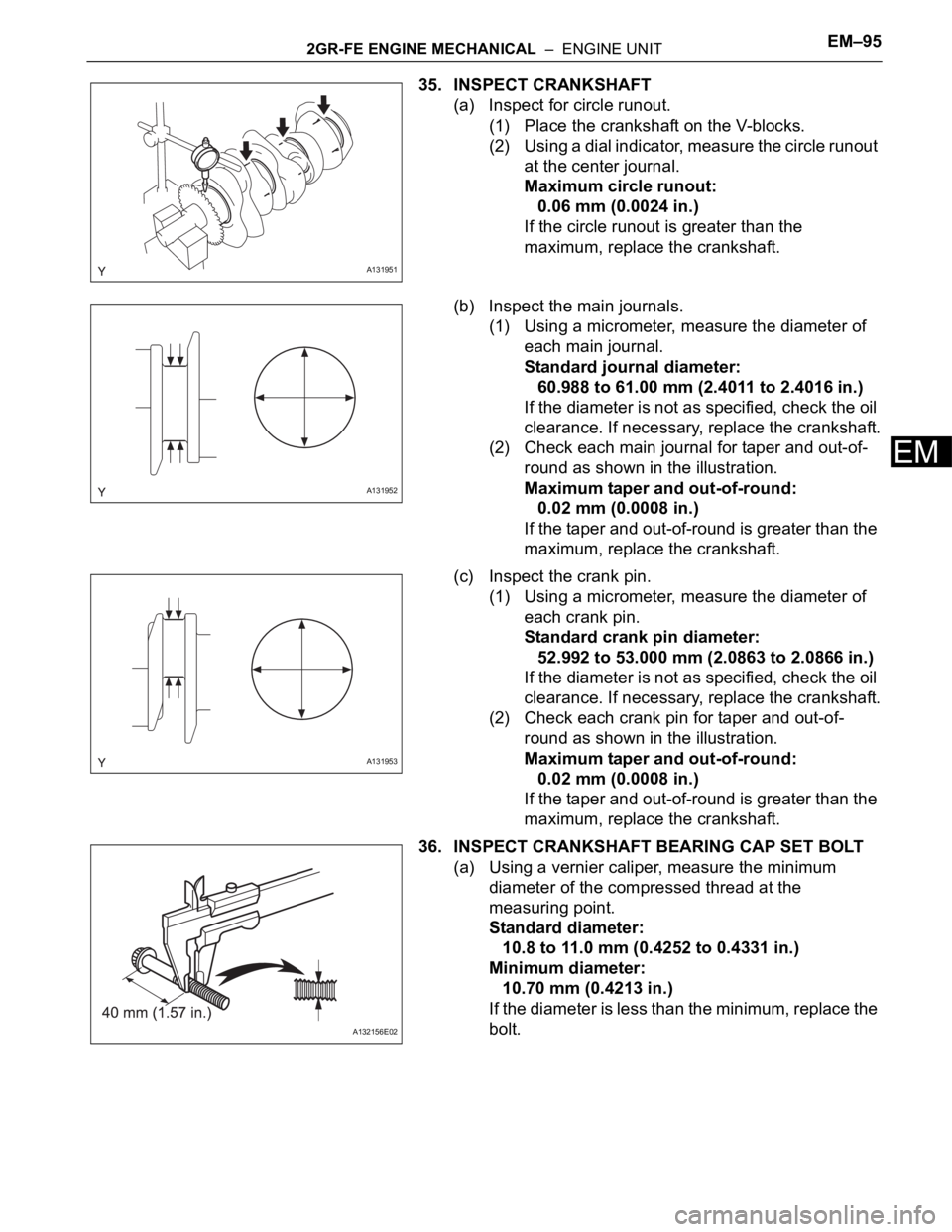
35. INSPECT CRANKSHAFT
(a) Inspect for circle runout.
(1) Place the crankshaft on the V-blocks.
(2) Using a dial indicator, measure the circle runout
at the center journal.
Maximum circle runout:
0.06 mm (0.0024 in.)
If the circle runout is greater than the
maximum, replace the crankshaft.
(b) Inspect the main journals.
(1) Using a micrometer, measure the diameter of
each main journal.
Standard journal diameter:
60.988 to 61.00 mm (2.4011 to 2.4016 in.)
If the diameter is not as specified, check the oil
clearance. If necessary, replace the crankshaft.
(2) Check each main journal for taper and out-of-
round as shown in the illustration.
Maximum taper and out-of-round:
0.02 mm (0.0008 in.)
If the taper and out-of-round is greater than the
maximum, replace the crankshaft.
(c) Inspect the crank pin.
(1) Using a micrometer, measure the diameter of
each crank pin.
Standard crank pin diameter:
52.992 to 53.000 mm (2.0863 to 2.0866 in.)
If the diameter is not as specified, check the oil
clearance. If necessary, replace the crankshaft.
(2) Check each crank pin for taper and out-of-
round as shown in the illustration.
Maximum taper and out-of-round:
0.02 mm (0.0008 in.)
If the taper and out-of-round is greater than the
maximum, replace the crankshaft.
36. INSPECT CRANKSHAFT BEARING CAP SET BOLT
(a) Using a vernier caliper, measure the minimum
diameter of the compressed thread at the
measuring point.
Standard diameter:
10.8 to 11.0 mm (0.4252 to 0.4331 in.)
Minimum diameter:
10.70 mm (0.4213 in.)
If the diameter is less than the minimum, replace the
bolt.
A131951
A131952
A131953
A132156E02
Page 734 of 2000
2GR-FE ENGINE MECHANICAL – ENGINE UNITEM–97
EM
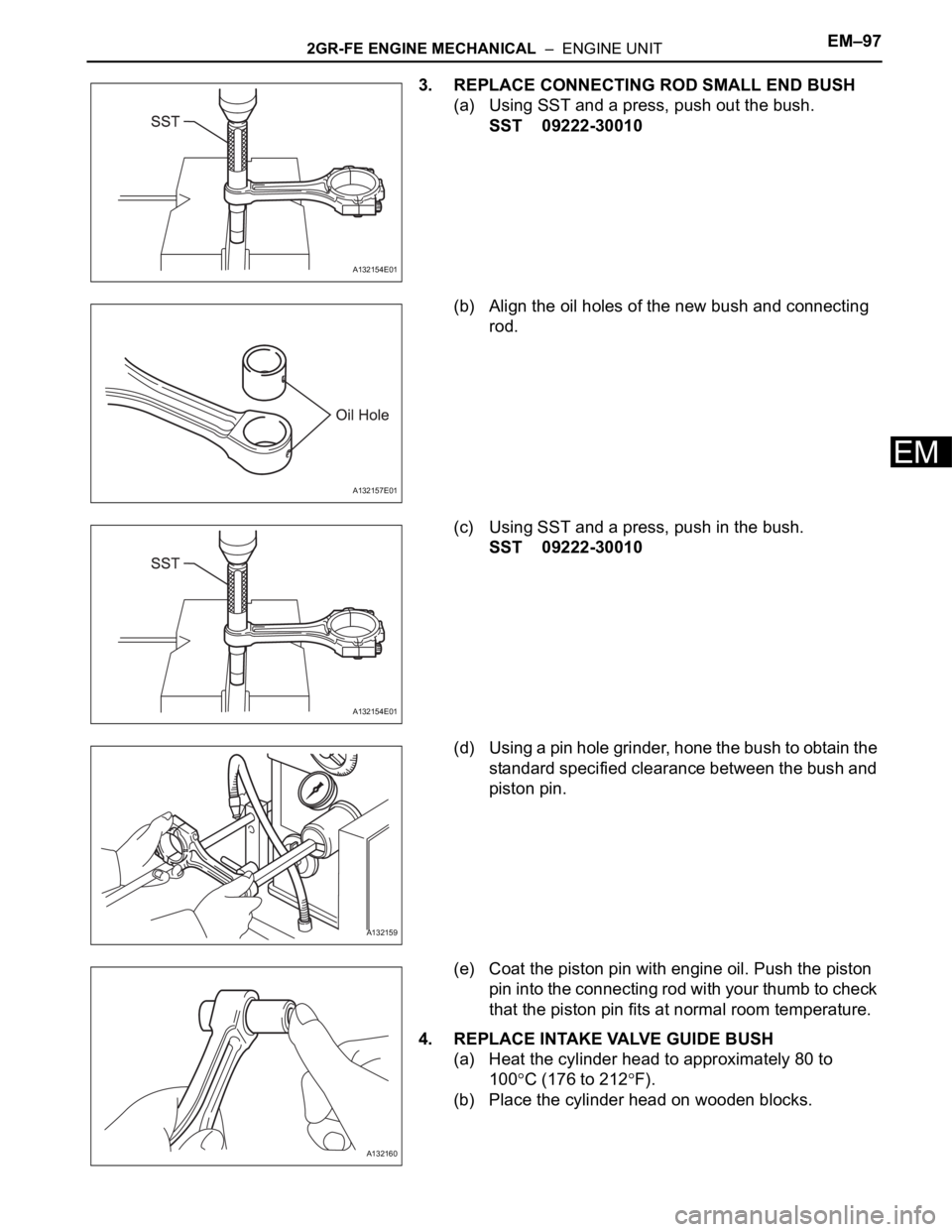
3. REPLACE CONNECTING ROD SMALL END BUSH
(a) Using SST and a press, push out the bush.
SST 09222-30010
(b) Align the oil holes of the new bush and connecting
rod.
(c) Using SST and a press, push in the bush.
SST 09222-30010
(d) Using a pin hole grinder, hone the bush to obtain the
standard specified clearance between the bush and
piston pin.
(e) Coat the piston pin with engine oil. Push the piston
pin into the connecting rod with your thumb to check
that the piston pin fits at normal room temperature.
4. REPLACE INTAKE VALVE GUIDE BUSH
(a) Heat the cylinder head to approximately 80 to
100
C (176 to 212F).
(b) Place the cylinder head on wooden blocks.
A132154E01
A132157E01
A132154E01
A132159
A132160
Page 744 of 2000
2GR-FE ENGINE MECHANICAL – ENGINE UNITEM–107
EM
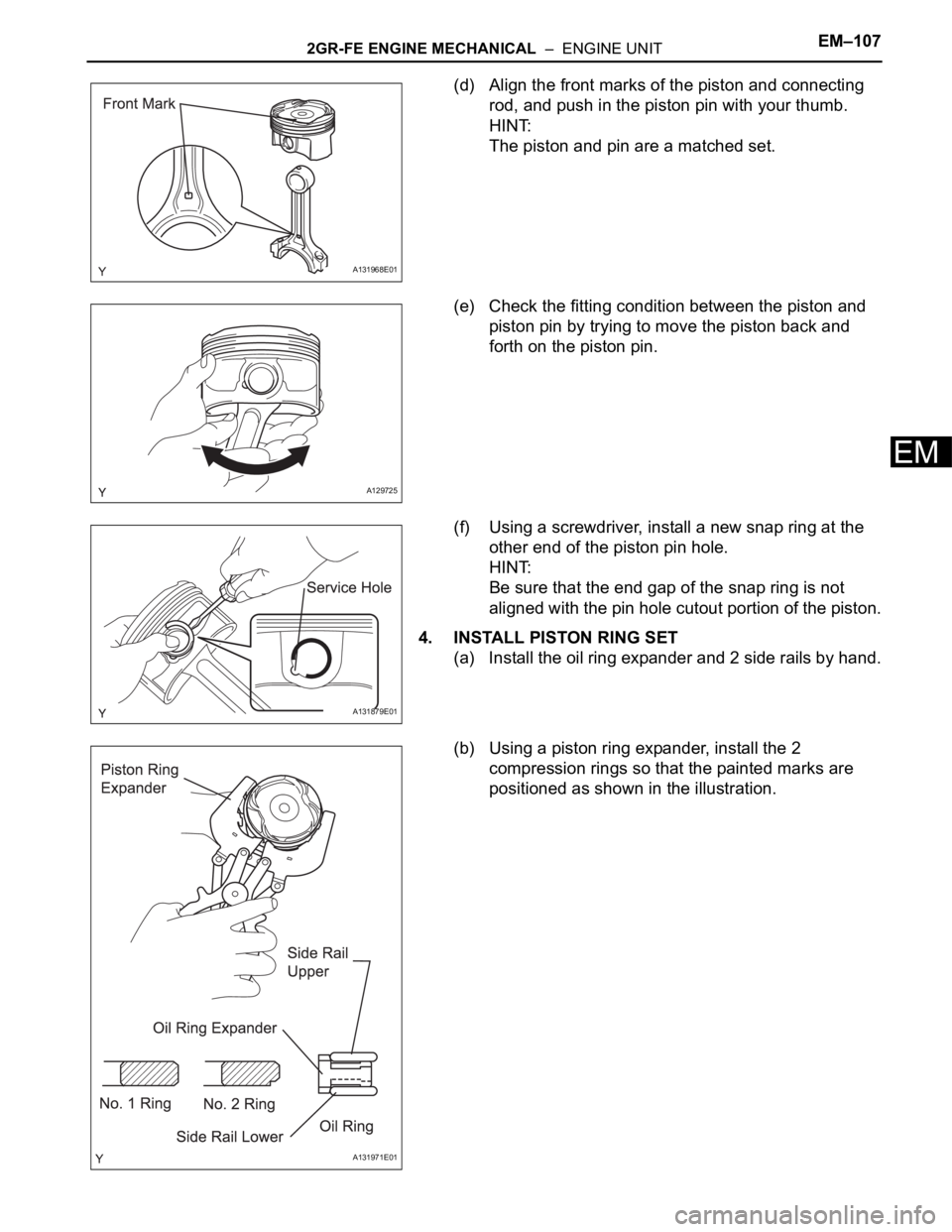
(d) Align the front marks of the piston and connecting
rod, and push in the piston pin with your thumb.
HINT:
The piston and pin are a matched set.
(e) Check the fitting condition between the piston and
piston pin by trying to move the piston back and
forth on the piston pin.
(f) Using a screwdriver, install a new snap ring at the
other end of the piston pin hole.
HINT:
Be sure that the end gap of the snap ring is not
aligned with the pin hole cutout portion of the piston.
4. INSTALL PISTON RING SET
(a) Install the oil ring expander and 2 side rails by hand.
(b) Using a piston ring expander, install the 2
compression rings so that the painted marks are
positioned as shown in the illustration.
A131968E01
A129725
A131879E01
A131971E01
Page 748 of 2000
2GR-FE ENGINE MECHANICAL – ENGINE UNITEM–111
EM
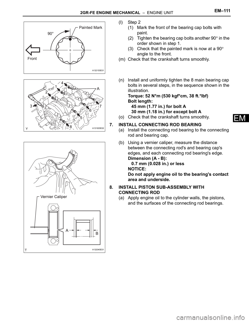
(l) Step 2
(1) Mark the front of the bearing cap bolts with
paint.
(2) Tighten the bearing cap bolts another 90
in the
order shown in step 1.
(3) Check that the painted mark is now at a 90
angle to the front.
(m) Check that the crankshaft turns smoothly.
(n) Install and uniformly tighten the 8 main bearing cap
bolts in several steps, in the sequence shown in the
illustration.
Torque: 52 N*m (530 kgf*cm, 38 ft.*lbf)
Bolt length:
45 mm (1.77 in.) for bolt A
30 mm (1.18 in.) for except bolt A
(o) Check that the crankshaft turns smoothly.
7. INSTALL CONNECTING ROD BEARING
(a) Install the connecting rod bearing to the connecting
rod and bearing cap.
(b) Using a vernier caliper, measure the distance
between the connecting rod's and bearing cap's
edges, and each connecting rod bearing's edge.
Dimension (A - B):
0.7 mm (0.028 in.) or less
NOTICE:
Do not apply engine oil to the bearing's contact
area and underside.
8. INSTALL PISTON SUB-ASSEMBLY WITH
CONNECTING ROD
(a) Apply engine oil to the cylinder walls, the pistons,
and the surfaces of the connecting rod bearings.
A132155E01
A131935E02
A132045E01
Page 749 of 2000
EM–1122GR-FE ENGINE MECHANICAL – ENGINE UNIT
EM
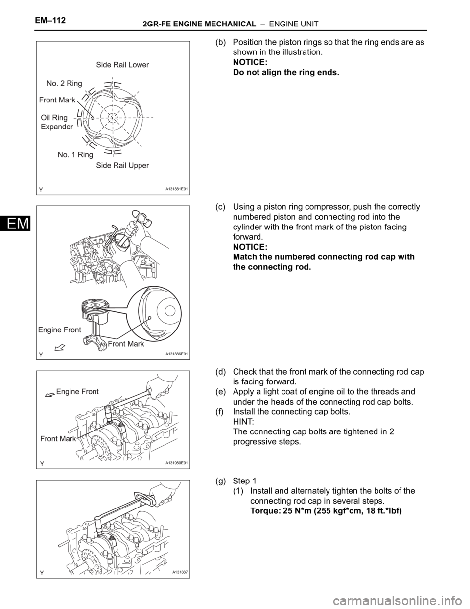
(b) Position the piston rings so that the ring ends are as
shown in the illustration.
NOTICE:
Do not align the ring ends.
(c) Using a piston ring compressor, push the correctly
numbered piston and connecting rod into the
cylinder with the front mark of the piston facing
forward.
NOTICE:
Match the numbered connecting rod cap with
the connecting rod.
(d) Check that the front mark of the connecting rod cap
is facing forward.
(e) Apply a light coat of engine oil to the threads and
under the heads of the connecting rod cap bolts.
(f) Install the connecting cap bolts.
HINT:
The connecting cap bolts are tightened in 2
progressive steps.
(g) Step 1
(1) Install and alternately tighten the bolts of the
connecting rod cap in several steps.
Torque: 25 N*m (255 kgf*cm, 18 ft.*lbf)
A131881E01
A131886E01
A131980E01
A131887
Page 750 of 2000
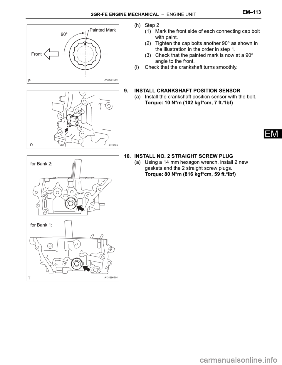
2GR-FE ENGINE MECHANICAL – ENGINE UNITEM–113
EM
(h) Step 2
(1) Mark the front side of each connecting cap bolt
with paint.
(2) Tighten the cap bolts another 90
as shown in
the illustration in the order in step 1.
(3) Check that the painted mark is now at a 90
angle to the front.
(i) Check that the crankshaft turns smoothly.
9. INSTALL CRANKSHAFT POSITION SENSOR
(a) Install the crankshaft position sensor with the bolt.
Torque: 10 N*m (102 kgf*cm, 7 ft.*lbf)
10. INSTALL NO. 2 STRAIGHT SCREW PLUG
(a) Using a 14 mm hexagon wrench, install 2 new
gaskets and the 2 straight screw plugs.
Torque: 80 N*m (816 kgf*cm, 59 ft.*lbf)
A132064E01
A129663
A131996E01