TOYOTA RAV4 2006 Service Repair Manual
Manufacturer: TOYOTA, Model Year: 2006, Model line: RAV4, Model: TOYOTA RAV4 2006Pages: 2000, PDF Size: 45.84 MB
Page 1641 of 2000

AIR CONDITIONING – AIR CONDITIONING SYSTEM (for Automatic Air Conditioning Sys-
tem)AC–13
AC
SYSTEM DESCRIPTION
1. GENERAL
(a) The air conditioning system has the following
features:
• In accordance with the temperature set using the
temperature control switch, the air conditioning
amplifier determines the outlet temperature
based on the input signals from various sensors.
In addition, corrections are made in accordance
with the signals from the water temperature
sensor to control the outlet air temperature.
• Controls the blower motor in accordance with the
airflow volume determined by the air conditioning
amplifier based on the input signals from various
sensors.
• Automatically changes the outlets in accordance
with the outlet mode ratio that is determined by
the air conditioning amplifier based on the input
signals from various sensors.
• Based on the signals from the ambient
temperature sensor, this system calculates the
outside temperature and indicates it in the multi-
information display in the combination meter
assembly.
• The left/right independent temperature control
and neural network control make air conditioner
control available to suit the persons in the driver
seat and in the passenger seat.
• Turns the rear defogger and outside rear mirror
heaters on for 15 minutes when the rear
defogger switch is pressed. Turns them off if the
switch is pressed while they are operating.
• Checks the sensors in accordance with the
operation of the air conditioner switches.
• The air conditioning amplifier has the function of
controlling the indicator lighting.
Page 1642 of 2000
AC–14AIR CONDITIONING – AIR CONDITIONING SYSTEM (for Automatic Air Conditioning Sys-
tem)
AC
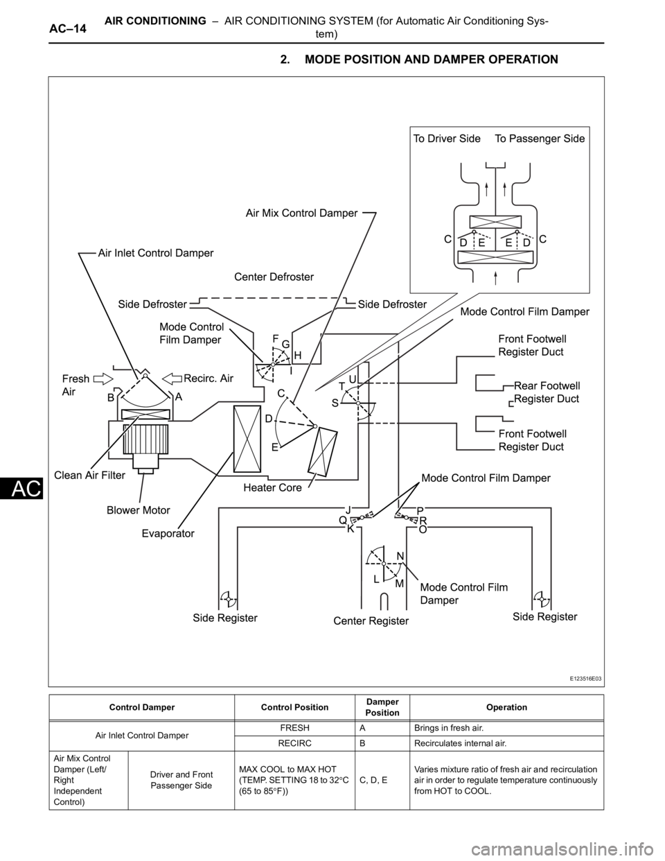
2. MODE POSITION AND DAMPER OPERATION
Control Damper Control PositionDamper
PositionOperation
Air Inlet Control DamperFRESH A Brings in fresh air.
RECIRC B Recirculates internal air.
Air Mix Control
Damper (Left/
Right
Independent
Control)Driver and Front
Passenger SideMAX COOL to MAX HOT
(TEMP. SETTING 18 to 32
C
(65 to 85
F))C, D, EVaries mixture ratio of fresh air and recirculation
air in order to regulate temperature continuously
from HOT to COOL.
E123516E03
Page 1643 of 2000
AIR CONDITIONING – AIR CONDITIONING SYSTEM (for Automatic Air Conditioning Sys-
tem)AC–15
AC
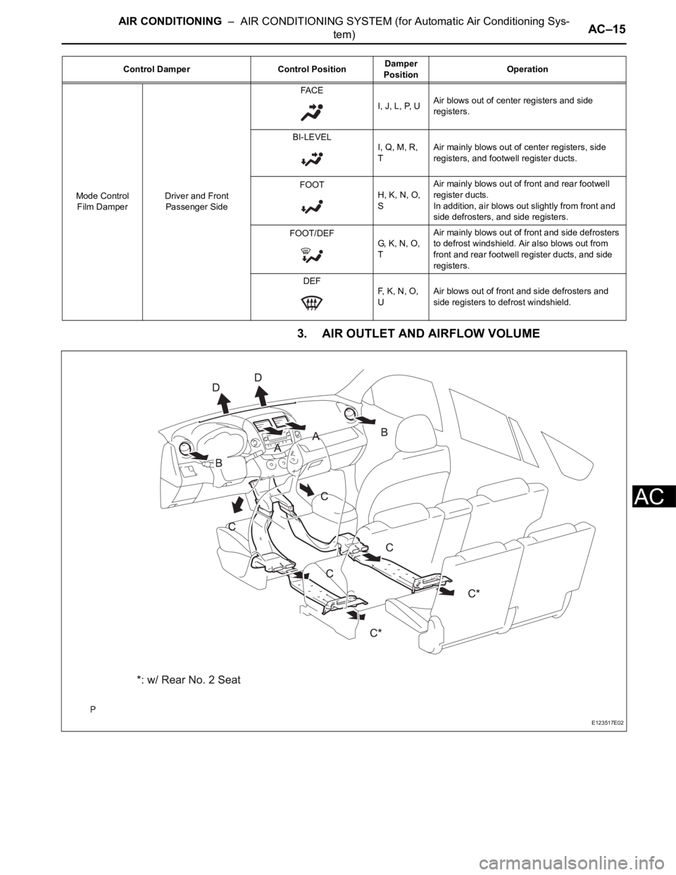
3. AIR OUTLET AND AIRFLOW VOLUME
Mode Control
Film DamperDriver and Front
Passenger SideFA C E
I, J, L, P, UAir blows out of center registers and side
registers.
BI-LEVEL
I, Q, M, R,
TAir mainly blows out of center registers, side
registers, and footwell register ducts.
FOOT
H, K, N, O,
SAir mainly blows out of front and rear footwell
register ducts.
In addition, air blows out slightly from front and
side defrosters, and side registers.
FOOT/DEF
G, K, N, O,
TAir mainly blows out of front and side defrosters
to defrost windshield. Air also blows out from
front and rear footwell register ducts, and side
registers.
DEF
F, K, N, O,
UAir blows out of front and side defrosters and
side registers to defrost windshield. Control Damper Control PositionDamper
PositionOperation
E123517E02
Page 1644 of 2000
AC–16AIR CONDITIONING – AIR CONDITIONING SYSTEM (for Automatic Air Conditioning Sys-
tem)
AC
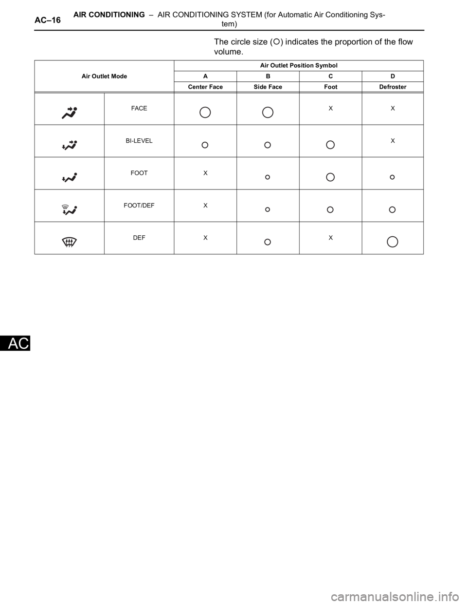
The circle size () indicates the proportion of the flow
volume.
Air Outlet ModeAir Outlet Position Symbol
ABCD
Center Face Side Face Foot Defroster
FA C E X X
BI-LEVELX
FOOT X
FOOT/DEF X
DEF X X
Page 1645 of 2000
AIR CONDITIONING – AIR CONDITIONING SYSTEM (for Automatic Air Conditioning Sys-
tem)AC–17
AC
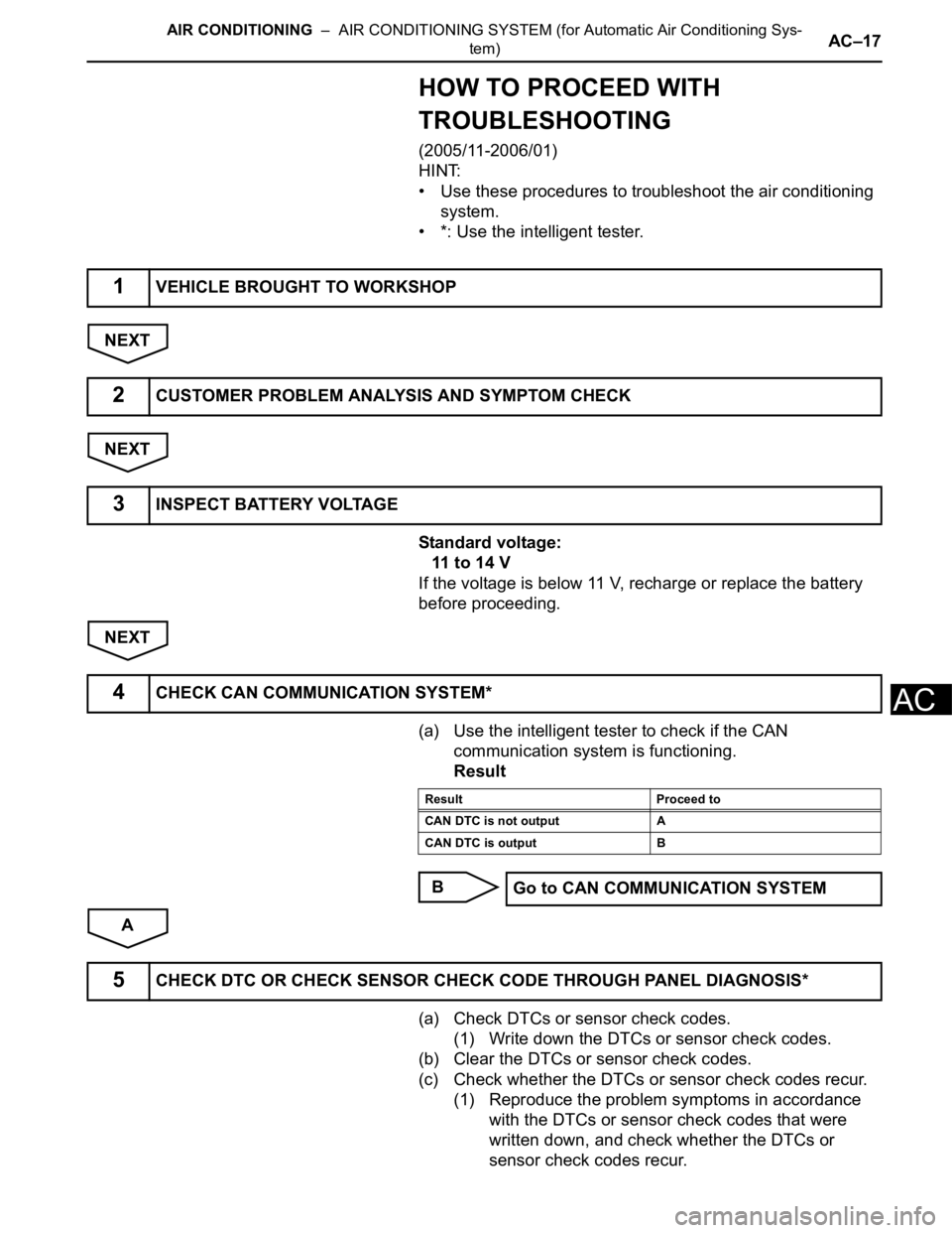
HOW TO PROCEED WITH
TROUBLESHOOTING
(2005/11-2006/01)
HINT:
• Use these procedures to troubleshoot the air conditioning
system.
• *: Use the intelligent tester.
NEXT
NEXT
Standard voltage:
11 to 14 V
If the voltage is below 11 V, recharge or replace the battery
before proceeding.
NEXT
(a) Use the intelligent tester to check if the CAN
communication system is functioning.
Result
B
A
(a) Check DTCs or sensor check codes.
(1) Write down the DTCs or sensor check codes.
(b) Clear the DTCs or sensor check codes.
(c) Check whether the DTCs or sensor check codes recur.
(1) Reproduce the problem symptoms in accordance
with the DTCs or sensor check codes that were
written down, and check whether the DTCs or
sensor check codes recur.
1VEHICLE BROUGHT TO WORKSHOP
2CUSTOMER PROBLEM ANALYSIS AND SYMPTOM CHECK
3INSPECT BATTERY VOLTAGE
4CHECK CAN COMMUNICATION SYSTEM*
Result Proceed to
CAN DTC is not output A
CAN DTC is output B
Go to CAN COMMUNICATION SYSTEM
5CHECK DTC OR CHECK SENSOR CHECK CODE THROUGH PANEL DIAGNOSIS*
Page 1646 of 2000
AC–18AIR CONDITIONING – AIR CONDITIONING SYSTEM (for Automatic Air Conditioning Sys-
tem)
AC
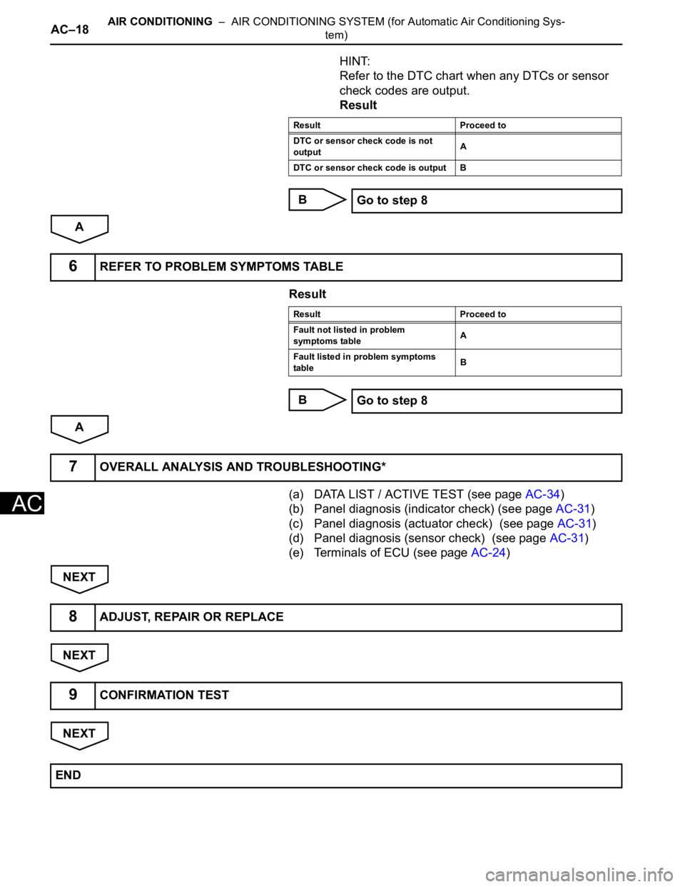
HINT:
Refer to the DTC chart when any DTCs or sensor
check codes are output.
Result
B
A
Result
B
A
(a) DATA LIST / ACTIVE TEST (see page AC-34)
(b) Panel diagnosis (indicator check) (see page AC-31)
(c) Panel diagnosis (actuator check) (see page AC-31)
(d) Panel diagnosis (sensor check) (see page AC-31)
(e) Terminals of ECU (see page AC-24)
NEXT
NEXT
NEXT
Result Proceed to
DTC or sensor check code is not
outputA
DTC or sensor check code is output B
Go to step 8
6REFER TO PROBLEM SYMPTOMS TABLE
Result Proceed to
Fault not listed in problem
symptoms tableA
Fault listed in problem symptoms
tableB
Go to step 8
7OVERALL ANALYSIS AND TROUBLESHOOTING*
8ADJUST, REPAIR OR REPLACE
9CONFIRMATION TEST
END
Page 1647 of 2000
AIR CONDITIONING – AIR CONDITIONING SYSTEM (for Automatic Air Conditioning Sys-
tem)AC–19
AC
HOW TO PROCEED WITH
TROUBLESHOOTING
(2006/01- )
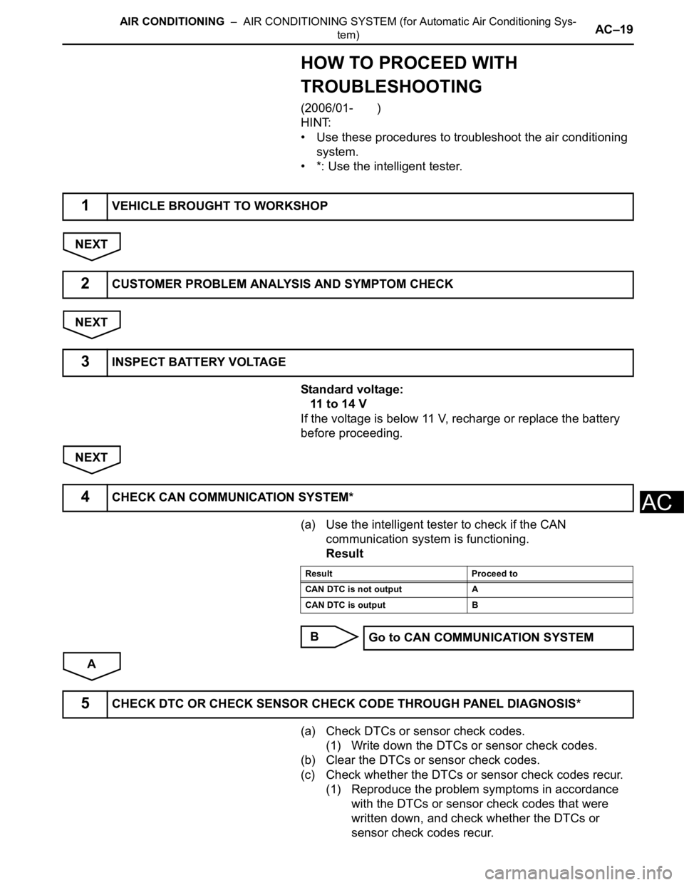
HINT:
• Use these procedures to troubleshoot the air conditioning
system.
• *: Use the intelligent tester.
NEXT
NEXT
Standard voltage:
11 to 14 V
If the voltage is below 11 V, recharge or replace the battery
before proceeding.
NEXT
(a) Use the intelligent tester to check if the CAN
communication system is functioning.
Result
B
A
(a) Check DTCs or sensor check codes.
(1) Write down the DTCs or sensor check codes.
(b) Clear the DTCs or sensor check codes.
(c) Check whether the DTCs or sensor check codes recur.
(1) Reproduce the problem symptoms in accordance
with the DTCs or sensor check codes that were
written down, and check whether the DTCs or
sensor check codes recur.
1VEHICLE BROUGHT TO WORKSHOP
2CUSTOMER PROBLEM ANALYSIS AND SYMPTOM CHECK
3INSPECT BATTERY VOLTAGE
4CHECK CAN COMMUNICATION SYSTEM*
Result Proceed to
CAN DTC is not output A
CAN DTC is output B
Go to CAN COMMUNICATION SYSTEM
5CHECK DTC OR CHECK SENSOR CHECK CODE THROUGH PANEL DIAGNOSIS*
Page 1648 of 2000
AC–20AIR CONDITIONING – AIR CONDITIONING SYSTEM (for Automatic Air Conditioning Sys-
tem)
AC
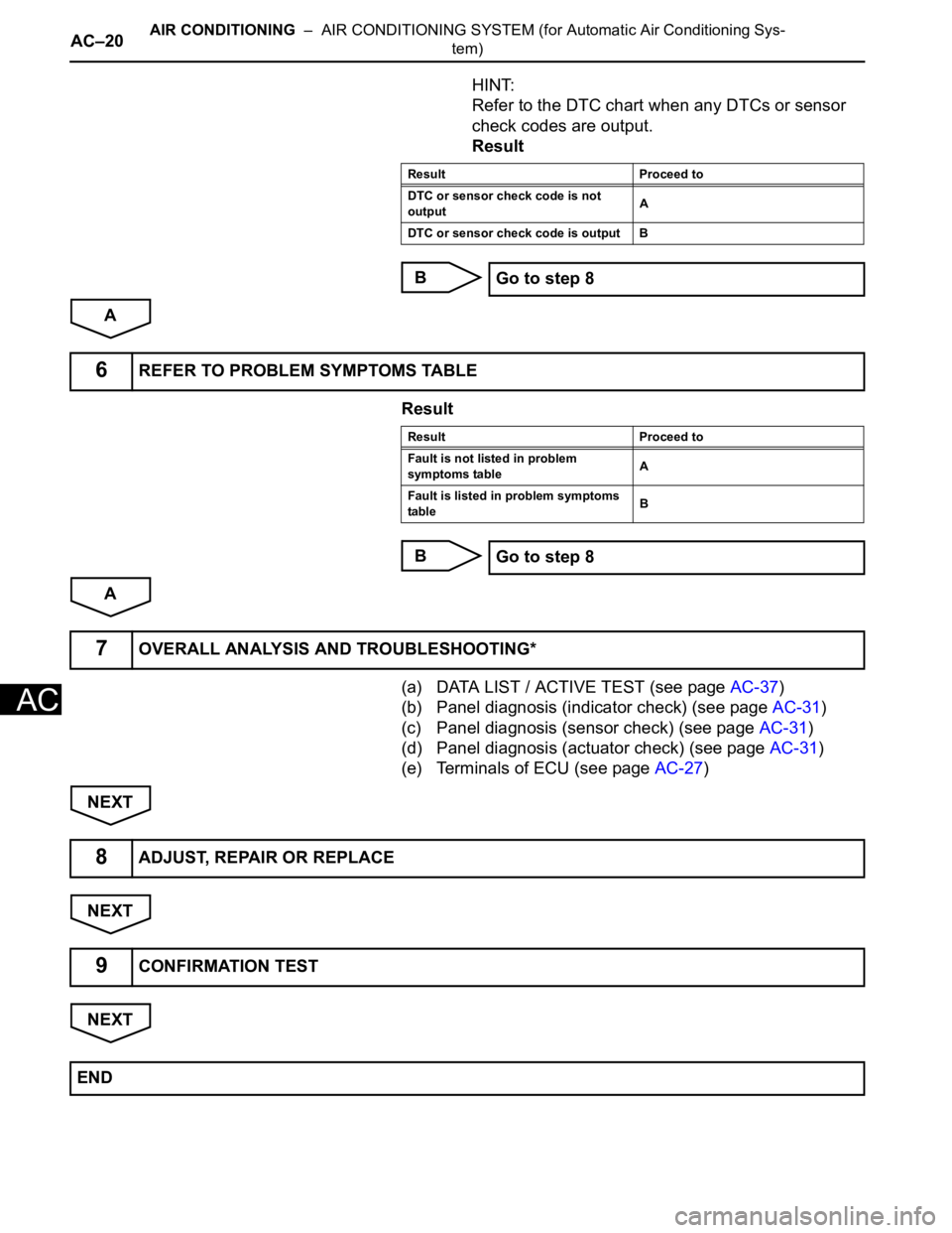
HINT:
Refer to the DTC chart when any DTCs or sensor
check codes are output.
Result
B
A
Result
B
A
(a) DATA LIST / ACTIVE TEST (see page AC-37)
(b) Panel diagnosis (indicator check) (see page AC-31)
(c) Panel diagnosis (sensor check) (see page AC-31)
(d) Panel diagnosis (actuator check) (see page AC-31)
(e) Terminals of ECU (see page AC-27)
NEXT
NEXT
NEXT
Result Proceed to
DTC or sensor check code is not
outputA
DTC or sensor check code is output B
Go to step 8
6REFER TO PROBLEM SYMPTOMS TABLE
Result Proceed to
Fault is not listed in problem
symptoms tableA
Fault is listed in problem symptoms
tableB
Go to step 8
7OVERALL ANALYSIS AND TROUBLESHOOTING*
8ADJUST, REPAIR OR REPLACE
9CONFIRMATION TEST
END
Page 1649 of 2000

AIR CONDITIONING – AIR CONDITIONING SYSTEM (for Automatic Air Conditioning Sys-
tem)AC–21
AC
CUSTOMIZE PARAMETERS
HINT:
The following items can be customized.
NOTICE:
• When the customer requests a change in a function,
first make sure that the function can be customized.
• Be sure to make a note of the current settings before
customizing.
• When troubleshooting a function, first make sure that
the function is set to the default setting.
Air conditioning system
Display (Item) Default Contents Setting
SET TEMP SHIFT
(Set Temperature Shift)NORMALTo control with shifted temperature against
display temperature+2 C / +1 C / NORMAL / -1 C / -2
C
AIR INLET MODE
(Air Inlet Mode)AUTOIn case of turning A/C ON when you desire to
make compartment cool down quickly, this is
function to change mode automatically to
RECIRCULATION modeMANUAL / AUTO
COMPRESSOR MODE
(Compressor Mode)AUTOFunction to turn A/C ON automatically by
pressing AUTO button when blower is ON
and A/C is OFFMANUAL / AUTO
COMPRS / DEF OPER
(Compressor / Air Inlet DEF
Operation)LINKFunction to turn A/C ON automatically linked
with FRONT DEF button when A/C is OFFNORMAL / LINK
EVAP CTRL
(Evaporator Control)AUTOFunction to set evaporator control to
AUTOMATIC position (AUTO) to save power,
or to coldest position (MANUAL) to dehumidify
air and to prevent windows from fogging upMANUAL / AUTO
FOOT / DEF MODE
(Foot / DEF auto mode)ONFunction to turn airflow from FOOT / DEF ON
automatically when AUTO MODE is ONOFF / ON
AUTO BLOW UP
(Foot / DEF automatic blower up
function)ONFunction to change blower level automatically
when defroster is ONOFF / ON
Page 1650 of 2000
AC–22AIR CONDITIONING – AIR CONDITIONING SYSTEM (for Automatic Air Conditioning Sys-
tem)
AC
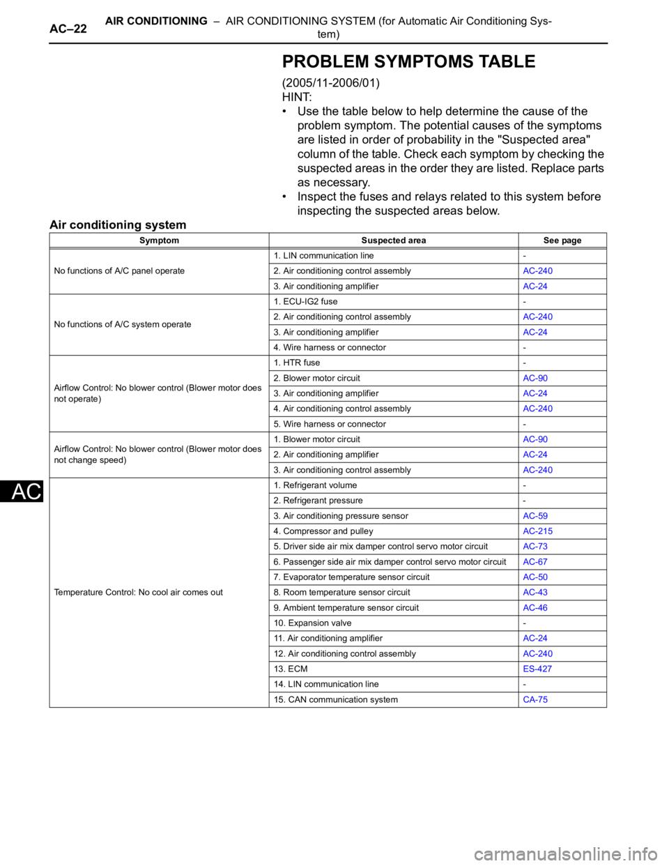
PROBLEM SYMPTOMS TABLE
(2005/11-2006/01)
HINT:
• Use the table below to help determine the cause of the
problem symptom. The potential causes of the symptoms
are listed in order of probability in the "Suspected area"
column of the table. Check each symptom by checking the
suspected areas in the order they are listed. Replace parts
as necessary.
• Inspect the fuses and relays related to this system before
inspecting the suspected areas below.
Air conditioning system
Symptom Suspected area See page
No functions of A/C panel operate1. LIN communication line -
2. Air conditioning control assemblyAC-240
3. Air conditioning amplifierAC-24
No functions of A/C system operate1. ECU-IG2 fuse -
2. Air conditioning control assemblyAC-240
3. Air conditioning amplifierAC-24
4. Wire harness or connector -
Airflow Control: No blower control (Blower motor does
not operate)1. HTR fuse -
2. Blower motor circuitAC-90
3. Air conditioning amplifierAC-24
4. Air conditioning control assemblyAC-240
5. Wire harness or connector -
Airflow Control: No blower control (Blower motor does
not change speed)1. Blower motor circuitAC-90
2. Air conditioning amplifierAC-24
3. Air conditioning control assemblyAC-240
Temperature Control: No cool air comes out1. Refrigerant volume -
2. Refrigerant pressure -
3. Air conditioning pressure sensorAC-59
4. Compressor and pulleyAC-215
5. Driver side air mix damper control servo motor circuitAC-73
6. Passenger side air mix damper control servo motor circuitAC-67
7. Evaporator temperature sensor circuitAC-50
8. Room temperature sensor circuitAC-43
9. Ambient temperature sensor circuitAC-46
10. Expansion valve -
11. Air conditioning amplifierAC-24
12. Air conditioning control assemblyAC-240
13. ECMES-427
14. LIN communication line -
15. CAN communication systemCA-75