TOYOTA RAV4 2006 Service Repair Manual
Manufacturer: TOYOTA, Model Year: 2006, Model line: RAV4, Model: TOYOTA RAV4 2006Pages: 2000, PDF Size: 45.84 MB
Page 1661 of 2000
AIR CONDITIONING – AIR MIX CONTROL SERVO MOTOR (for Automatic Air Conditioning
System)AC–215
AC
INSTALLATION
1. INSTALL AIR MIX CONTROL SERVO MOTOR (See
page AC-196)
2. INSTALL AIR CONDITIONING UNIT
(a) Install the air conditioning radiator (see page AC-
197).
Page 1662 of 2000
AIR CONDITIONING – COMPRESSOR AND PULLEY (for 2AZ-FE)AC–217
AC
INSTALLATION
1. ADJUST ADJUST COMPRESSOR OIL
(a) When replacing the compressor and magnetic
clutch with a new one, gradually discharge the
refrigerant gas from the service valve, and drain the
following amount of oil from the new compressor
and magnetic clutch before installation.
Standard:
(Oil capacity inside the new compressor and
magnetic clutch: 130 + 15 cc (4.6 + 0.51 fl.oz.) )
-(Remaining oil amount in the removed
compressor and magnetic clutch) = (Oil
amount to be removed from the new
compressor when replacing)
NOTICE:
• When checking the compressor oil level,
observe the precautions on the cooler
removal/installation.
• If a new compressor and magnetic clutch is
installed without removing some oil
remaining in the pipes of the vehicle, the oil
amount will be too large. This prevents heat
exchange in the refrigerant cycle and causes
refrigerant failure.
• If the volume of oil remaining in the removed
compressor and magnetic clutch is too small,
check for oil leakage.
• Be sure to use ND-OIL 8 or equivalent for
compressor oil.
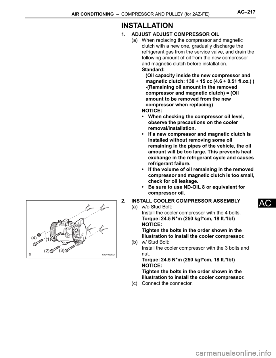
2. INSTALL COOLER COMPRESSOR ASSEMBLY
(a) w/o Stud Bolt:
Install the cooler compressor with the 4 bolts.
Torque: 24.5 N*m (250 kgf*cm, 18 ft.*lbf)
NOTICE:
Tighten the bolts in the order shown in the
illustration to install the cooler compressor.
(b) w/ Stud Bolt:
Install the cooler compressor with the 3 bolts and
nut.
Torque: 24.5 N*m (250 kgf*cm, 18 ft.*lbf)
NOTICE:
Tighten the bolts in the order shown in the
illustration to install the cooler compressor.
(c) Connect the connector.
E134063E01
Page 1663 of 2000
AC–218AIR CONDITIONING – COMPRESSOR AND PULLEY (for 2AZ-FE)
AC
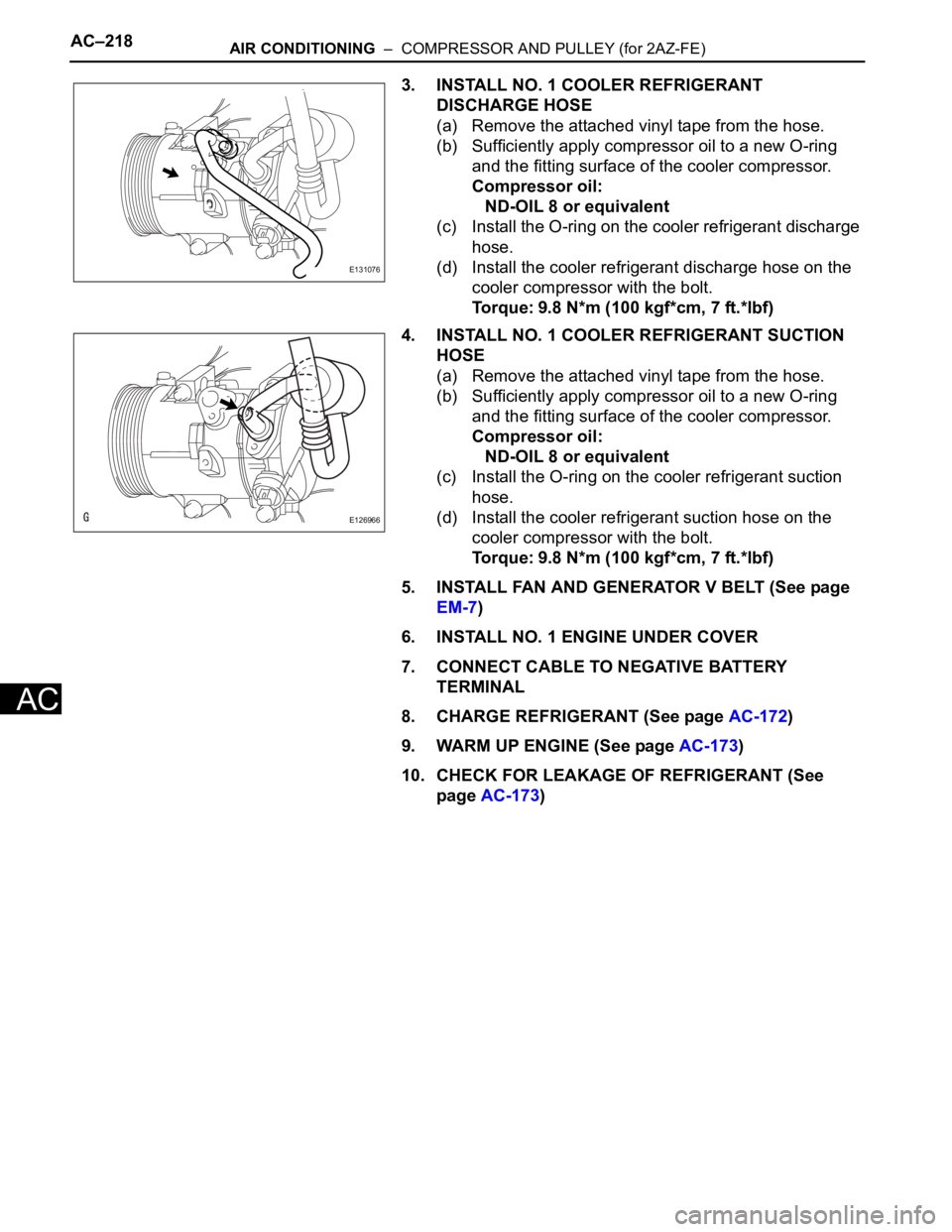
3. INSTALL NO. 1 COOLER REFRIGERANT
DISCHARGE HOSE
(a) Remove the attached vinyl tape from the hose.
(b) Sufficiently apply compressor oil to a new O-ring
and the fitting surface of the cooler compressor.
Compressor oil:
ND-OIL 8 or equivalent
(c) Install the O-ring on the cooler refrigerant discharge
hose.
(d) Install the cooler refrigerant discharge hose on the
cooler compressor with the bolt.
Torque: 9.8 N*m (100 kgf*cm, 7 ft.*lbf)
4. INSTALL NO. 1 COOLER REFRIGERANT SUCTION
HOSE
(a) Remove the attached vinyl tape from the hose.
(b) Sufficiently apply compressor oil to a new O-ring
and the fitting surface of the cooler compressor.
Compressor oil:
ND-OIL 8 or equivalent
(c) Install the O-ring on the cooler refrigerant suction
hose.
(d) Install the cooler refrigerant suction hose on the
cooler compressor with the bolt.
Torque: 9.8 N*m (100 kgf*cm, 7 ft.*lbf)
5. INSTALL FAN AND GENERATOR V BELT (See page
EM-7)
6. INSTALL NO. 1 ENGINE UNDER COVER
7. CONNECT CABLE TO NEGATIVE BATTERY
TERMINAL
8. CHARGE REFRIGERANT (See page AC-172)
9. WARM UP ENGINE (See page AC-173)
10. CHECK FOR LEAKAGE OF REFRIGERANT (See
page AC-173)
E131076
E126966
Page 1664 of 2000
AIR CONDITIONING – COMPRESSOR AND PULLEY (for 2GR-FE)AC–221
AC
INSTALLATION
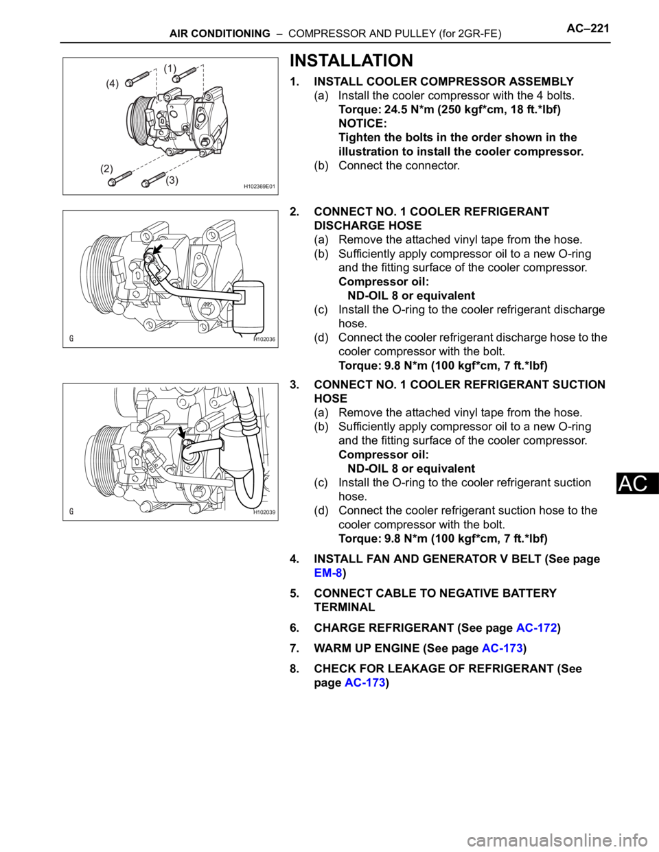
1. INSTALL COOLER COMPRESSOR ASSEMBLY
(a) Install the cooler compressor with the 4 bolts.
Torque: 24.5 N*m (250 kgf*cm, 18 ft.*lbf)
NOTICE:
Tighten the bolts in the order shown in the
illustration to install the cooler compressor.
(b) Connect the connector.
2. CONNECT NO. 1 COOLER REFRIGERANT
DISCHARGE HOSE
(a) Remove the attached vinyl tape from the hose.
(b) Sufficiently apply compressor oil to a new O-ring
and the fitting surface of the cooler compressor.
Compressor oil:
ND-OIL 8 or equivalent
(c) Install the O-ring to the cooler refrigerant discharge
hose.
(d) Connect the cooler refrigerant discharge hose to the
cooler compressor with the bolt.
Torque: 9.8 N*m (100 kgf*cm, 7 ft.*lbf)
3. CONNECT NO. 1 COOLER REFRIGERANT SUCTION
HOSE
(a) Remove the attached vinyl tape from the hose.
(b) Sufficiently apply compressor oil to a new O-ring
and the fitting surface of the cooler compressor.
Compressor oil:
ND-OIL 8 or equivalent
(c) Install the O-ring to the cooler refrigerant suction
hose.
(d) Connect the cooler refrigerant suction hose to the
cooler compressor with the bolt.
Torque: 9.8 N*m (100 kgf*cm, 7 ft.*lbf)
4. INSTALL FAN AND GENERATOR V BELT (See page
EM-8)
5. CONNECT CABLE TO NEGATIVE BATTERY
TERMINAL
6. CHARGE REFRIGERANT (See page AC-172)
7. WARM UP ENGINE (See page AC-173)
8. CHECK FOR LEAKAGE OF REFRIGERANT (See
page AC-173)
H102369E01
H102036
H102039
Page 1665 of 2000

AC–224AIR CONDITIONING – CONDENSER
AC
ON-VEHICLE INSPECTION
1. INSPECT COOLER CONDENSER ASSEMBLY
(a) If the fins of the cooler condenser are dirty, clean
them with water. Dry the fins with compressed air.
NOTICE:
Do not damage the fins of the condenser.
(b) If a fin of the cooler condenser is bent, straighten it
using a screwdriver or pliers.
2. CHECK CONDENSER FOR LEAKAGE OF
REFRIGERANT
(a) Using a halogen leak detector, check the pipe joints
for gas leakage.
(b) If gas leakage is detected in a joint, check the
torque of the joint.
Page 1666 of 2000
AIR CONDITIONING – CONDENSERAC–225
AC
REMOVAL
1. DISCHARGE REFRIGERANT FROM
REFRIGERATION SYSTEM (See page AC-172)
2. DISCONNECT CABLE FROM NEGATIVE BATTERY
TERMINAL
CAUTION:
Wait at least 90 seconds after disconnecting the
cable from the negative (-) battery terminal to
prevent airbag and seat belt pretensioner activation.
3. REMOVE FRONT BUMPER COVER
(a) Remove front bumper cover (see page ET-4).
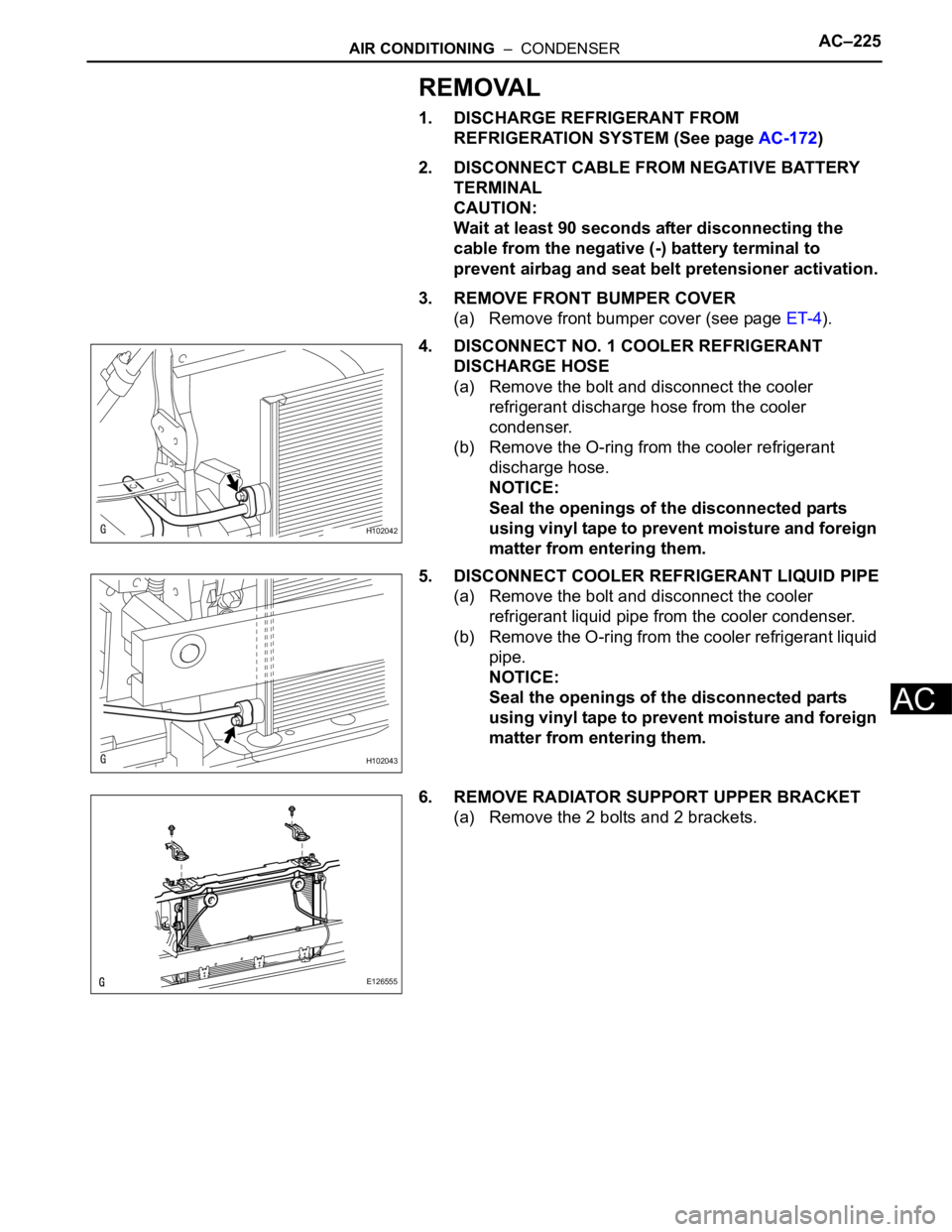
4. DISCONNECT NO. 1 COOLER REFRIGERANT
DISCHARGE HOSE
(a) Remove the bolt and disconnect the cooler
refrigerant discharge hose from the cooler
condenser.
(b) Remove the O-ring from the cooler refrigerant
discharge hose.
NOTICE:
Seal the openings of the disconnected parts
using vinyl tape to prevent moisture and foreign
matter from entering them.
5. DISCONNECT COOLER REFRIGERANT LIQUID PIPE
(a) Remove the bolt and disconnect the cooler
refrigerant liquid pipe from the cooler condenser.
(b) Remove the O-ring from the cooler refrigerant liquid
pipe.
NOTICE:
Seal the openings of the disconnected parts
using vinyl tape to prevent moisture and foreign
matter from entering them.
6. REMOVE RADIATOR SUPPORT UPPER BRACKET
(a) Remove the 2 bolts and 2 brackets.
H102042
H102043
E126555
Page 1667 of 2000
AC–226AIR CONDITIONING – CONDENSER
AC
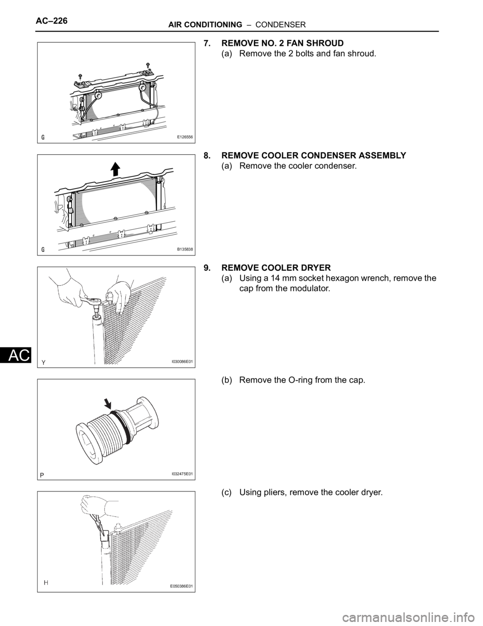
7. REMOVE NO. 2 FAN SHROUD
(a) Remove the 2 bolts and fan shroud.
8. REMOVE COOLER CONDENSER ASSEMBLY
(a) Remove the cooler condenser.
9. REMOVE COOLER DRYER
(a) Using a 14 mm socket hexagon wrench, remove the
cap from the modulator.
(b) Remove the O-ring from the cap.
(c) Using pliers, remove the cooler dryer.
E126556
B135838
I030086E01
I032475E01
E050386E01
Page 1668 of 2000
AIR CONDITIONING – CONDENSERAC–227
AC
INSTALLATION
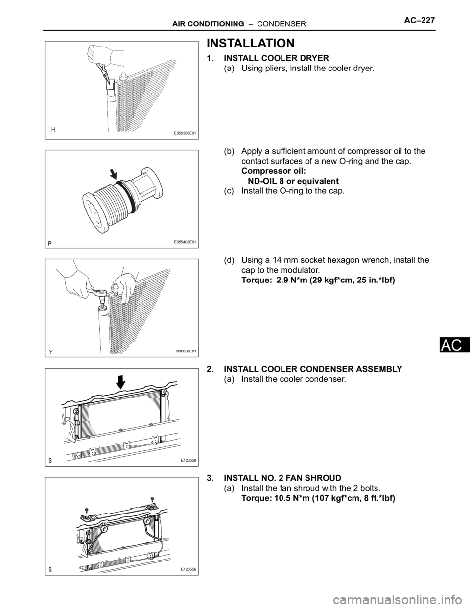
1. INSTALL COOLER DRYER
(a) Using pliers, install the cooler dryer.
(b) Apply a sufficient amount of compressor oil to the
contact surfaces of a new O-ring and the cap.
Compressor oil:
ND-OIL 8 or equivalent
(c) Install the O-ring to the cap.
(d) Using a 14 mm socket hexagon wrench, install the
cap to the modulator.
Torque: 2.9 N*m (29 kgf*cm, 25 in.*lbf)
2. INSTALL COOLER CONDENSER ASSEMBLY
(a) Install the cooler condenser.
3. INSTALL NO. 2 FAN SHROUD
(a) Install the fan shroud with the 2 bolts.
Torque: 10.5 N*m (107 kgf*cm, 8 ft.*lbf)
E050386E01
E055408E01
I030086E01
E126558
E126556
Page 1669 of 2000
AC–228AIR CONDITIONING – CONDENSER
AC
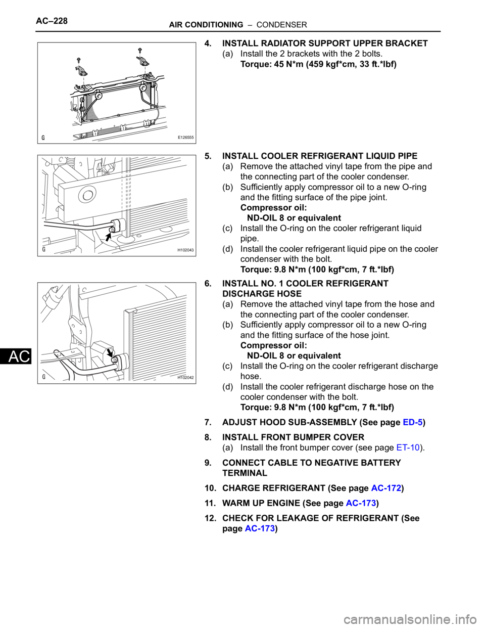
4. INSTALL RADIATOR SUPPORT UPPER BRACKET
(a) Install the 2 brackets with the 2 bolts.
Torque: 45 N*m (459 kgf*cm, 33 ft.*lbf)
5. INSTALL COOLER REFRIGERANT LIQUID PIPE
(a) Remove the attached vinyl tape from the pipe and
the connecting part of the cooler condenser.
(b) Sufficiently apply compressor oil to a new O-ring
and the fitting surface of the pipe joint.
Compressor oil:
ND-OIL 8 or equivalent
(c) Install the O-ring on the cooler refrigerant liquid
pipe.
(d) Install the cooler refrigerant liquid pipe on the cooler
condenser with the bolt.
Torque: 9.8 N*m (100 kgf*cm, 7 ft.*lbf)
6. INSTALL NO. 1 COOLER REFRIGERANT
DISCHARGE HOSE
(a) Remove the attached vinyl tape from the hose and
the connecting part of the cooler condenser.
(b) Sufficiently apply compressor oil to a new O-ring
and the fitting surface of the hose joint.
Compressor oil:
ND-OIL 8 or equivalent
(c) Install the O-ring on the cooler refrigerant discharge
hose.
(d) Install the cooler refrigerant discharge hose on the
cooler condenser with the bolt.
Torque: 9.8 N*m (100 kgf*cm, 7 ft.*lbf)
7. ADJUST HOOD SUB-ASSEMBLY (See page ED-5)
8. INSTALL FRONT BUMPER COVER
(a) Install the front bumper cover (see page ET-10).
9. CONNECT CABLE TO NEGATIVE BATTERY
TERMINAL
10. CHARGE REFRIGERANT (See page AC-172)
11. WARM UP ENGINE (See page AC-173)
12. CHECK FOR LEAKAGE OF REFRIGERANT (See
page AC-173)
E126555
H102043
H102042
Page 1670 of 2000
AIR CONDITIONING – ROOM TEMPERATURE SENSOR (for Automatic Air Conditioning
System)AC–231
AC
INSTALLATION
1. INSTALL ROOM TEMPERATURE SENSOR
(a) Attach the claws to install the sensor.
(b) Connect the connector.
(c) Connect the duct.
2. INSTALL LOWER INSTRUMENT PANEL
(a) Install the lower instrument panel (see page IP-23).