TOYOTA RAV4 2006 Service Repair Manual
Manufacturer: TOYOTA, Model Year: 2006, Model line: RAV4, Model: TOYOTA RAV4 2006Pages: 2000, PDF Size: 45.84 MB
Page 1741 of 2000
SUPPLEMENTAL RESTRAINT SYSTEM – SEAT POSITION SENSORRS–393
RS
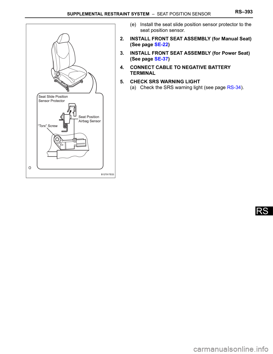
(e) Install the seat slide position sensor protector to the
seat position sensor.
2. INSTALL FRONT SEAT ASSEMBLY (for Manual Seat)
(See page SE-22)
3. INSTALL FRONT SEAT ASSEMBLY (for Power Seat)
(See page SE-37)
4. CONNECT CABLE TO NEGATIVE BATTERY
TERMINAL
5. CHECK SRS WARNING LIGHT
(a) Check the SRS warning light (see page RS-34).
B127917E03
Page 1742 of 2000
RS–394SUPPLEMENTAL RESTRAINT SYSTEM – OCCUPANT CLASSIFICATION ECU
RS
REMOVAL
1. DISCONNECT CABLE FROM NEGATIVE BATTERY
TERMINAL
CAUTION:
Wait at least 90 seconds after disconnecting the
cable from the negative (-) battery terminal to
prevent airbag and seat belt pretensioner activation.
2. REMOVE FRONT SEAT ASSEMBLY (for Manual Seat)
(See page SE-11)
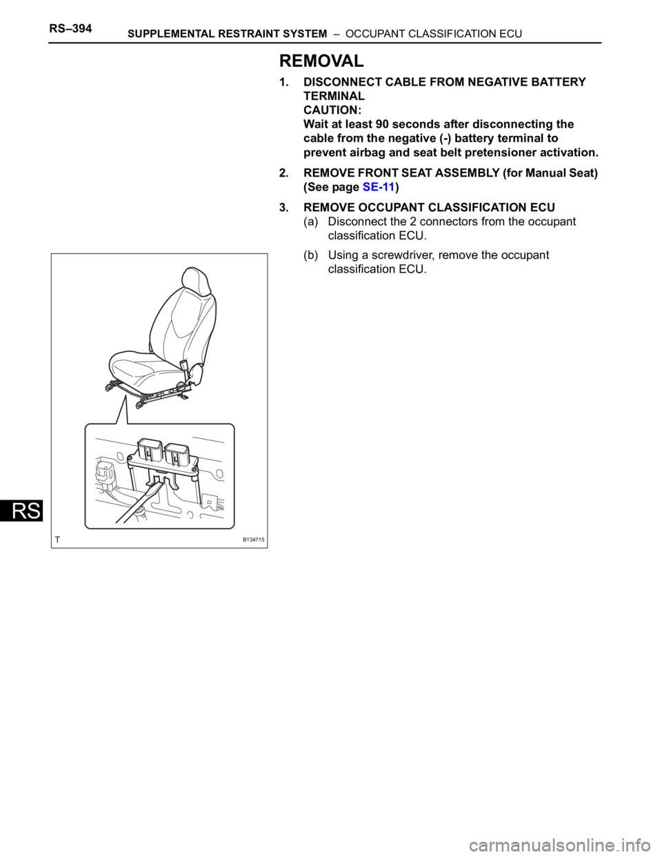
3. REMOVE OCCUPANT CLASSIFICATION ECU
(a) Disconnect the 2 connectors from the occupant
classification ECU.
(b) Using a screwdriver, remove the occupant
classification ECU.
B134715
Page 1743 of 2000
SUPPLEMENTAL RESTRAINT SYSTEM – OCCUPANT CLASSIFICATION ECURS–395
RS
INSTALLATION
1. INSTALL OCCUPANT CLASSIFICATION ECU
(a) Check that the ignition switch is off.
(b) Check that the negative battery (-) terminal is
disconnected.
CAUTION:
After disconnecting the negative battery
terminal, wait for at least 90 seconds before
starting the operation.
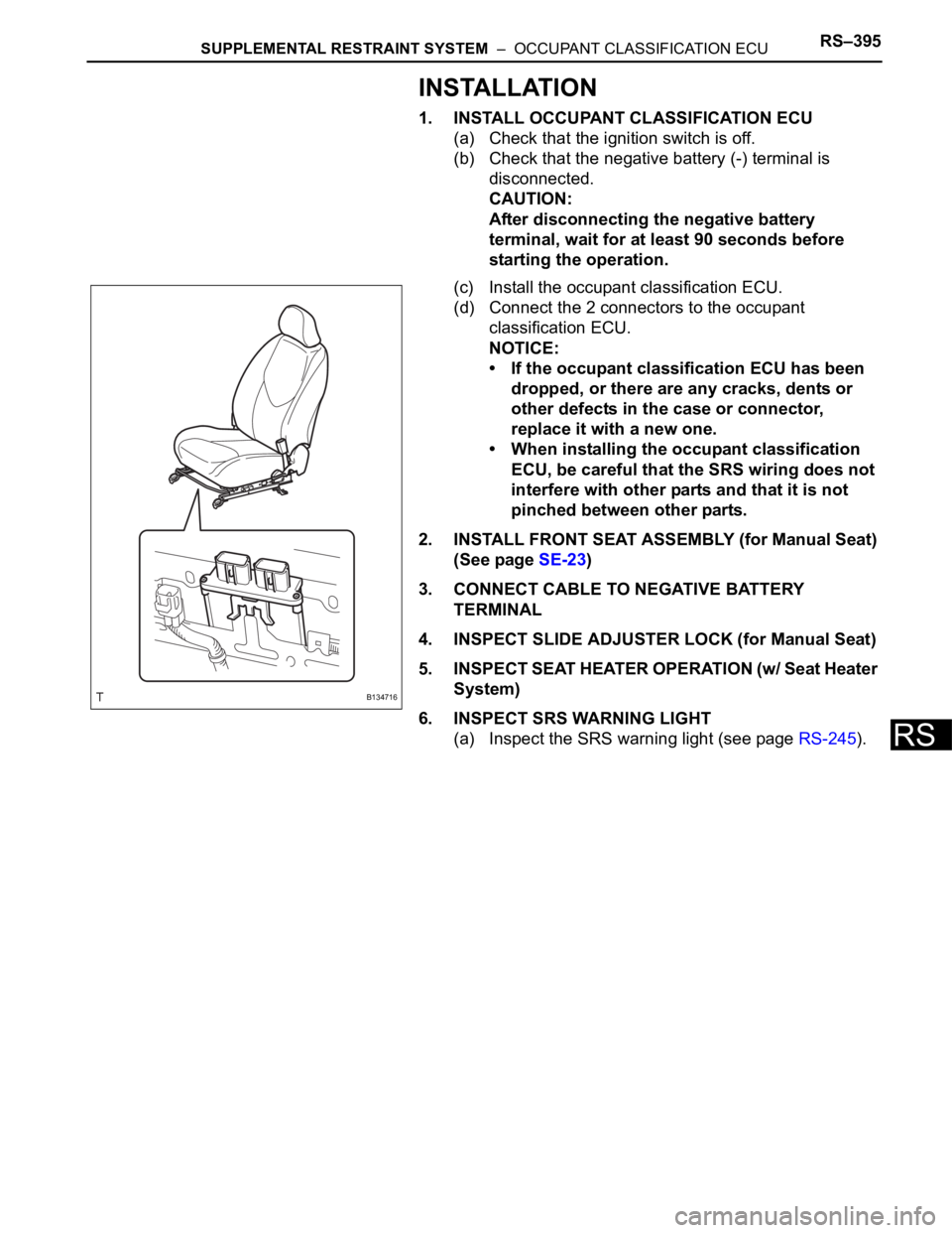
(c) Install the occupant classification ECU.
(d) Connect the 2 connectors to the occupant
classification ECU.
NOTICE:
• If the occupant classification ECU has been
dropped, or there are any cracks, dents or
other defects in the case or connector,
replace it with a new one.
• When installing the occupant classification
ECU, be careful that the SRS wiring does not
interfere with other parts and that it is not
pinched between other parts.
2. INSTALL FRONT SEAT ASSEMBLY (for Manual Seat)
(See page SE-23)
3. CONNECT CABLE TO NEGATIVE BATTERY
TERMINAL
4. INSPECT SLIDE ADJUSTER LOCK (for Manual Seat)
5. INSPECT SEAT HEATER OPERATION (w/ Seat Heater
System)
6. INSPECT SRS WARNING LIGHT
(a) Inspect the SRS warning light (see page RS-245).
B134716
Page 1744 of 2000

SB–6SEAT BELT – SEAT BELT WARNING SYSTEM
SB
OPERATION CHECK
1. INSPECT DRIVER SIDE SEAT BELT WARNING LIGHT
(a) Turn the ignition switch ON.
(b) When the driver seat belt is not fastened, check that
the driver seat belt warning light on the combination
meter blinks.
(c) When the driver seat belt is fastened, check that the
driver seat belt warning light on the combination
meter is off.
2. INSPECT PASSENGER SIDE SEAT BELT WARNING
LIGHT (For Automatic Air Conditioning System)
(a) Turn the ignition switch ON.
(b) When the front passenger seat belt is not fastened
with the passenger seat occupied, check that the
front passenger seat belt warning light on the heater
control panel display blinks.
(c) When the front passenger seat belt is fastened with
the passenger seat occupied, check that the front
passenger seat belt warning light on the heater
control panel display is off.
3. REMOVE PASSENGER SIDE SEAT BELT WARNING
LIGHT (For Manual Air Conditioning System)
(a) Turn the ignition switch ON.
(b) When the front passenger seat belt is not fastened
with the passenger seat occupied, check that the
front passenger seat belt warning light on the clock
panel blinks.
(c) When the front passenger seat belt is fastened with
the passenger seat occupied, check that the front
passenger seat belt warning light on the clock panel
is off.
4. INSPECT SEAT BELT WARNING BUZZER
HINT:
If the buzzer does not sound, the buzzer cancel setting
may be set to ON.
(a) Turn the ignition switch ON.
(b) When the vehicle is driven at approximately 20 km/h
(12.4 mph) or more while the driver or front
passenger seat belt is not fastened, check that the
buzzer in the combination meter sounds at 1.2
second intervals for 30 seconds.
(c) 30 seconds after the buzzer has first sounded,
check that the buzzer sounds at 0.4 second
intervals for 90 seconds.
(d) 120 seconds after the buzzer has first sounded,
check that the buzzer stops.
(e) After the buzzer has stopped, turn the ignition
switch off and then start the engine again. Drive the
vehicle at approximately 25 km/h (16 mph) or more
while the driver or front passenger seat belt is not
fastened, and then check that the buzzer sounds
again.
Page 1745 of 2000

SEAT BELT – SEAT BELT WARNING SYSTEMSB–7
SB
(f) After the buzzer has stopped, fasten the driver and
front passenger seat belts. Drive the vehicle at
approximately 25 km/h (16 mph) or more and
unfasten the driver or front passenger seat belt, and
then check that the buzzer sounds again.
(g) After the buzzer has stopped, move the shift lever to
the R position, and then move it to the D position.
Drive the vehicle at approximately 25 km/h (16 mph)
or more, and then check that the buzzer sounds
again.
Page 1746 of 2000

SB–8SEAT BELT – SEAT BELT WARNING SYSTEM
SB
PROBLEM SYMPTOMS TABLE
HINT:
Use the table below to help determine the cause of the
problem symptom. The potential causes of the symptoms are
listed in order of probability in the "Suspected Area" column
of the table. Check each symptom by checking the suspected
areas in the order they are listed. Replace parts as
necessary.
Seat belt warning system
Symptom Suspected area See page
Diver side seat belt warning light does not operate1. Front seat inner belt LHSB-12
2. Center airbag sensor assemblySB-12
3. Combination meterSB-12
4. Wire harnessSB-12
Front passenger side seat belt warning light does not
operate1. Front seat inner belt RHSB-15
2. Combination meterSB-15
3. Occupant detection sensorSB-15
4. Heater control panelSB-15
5. Wire harnessSB-15
Page 1747 of 2000
SEAT BELT – SEAT BELT WARNING SYSTEMSB–9
SB
TERMINALS OF ECU
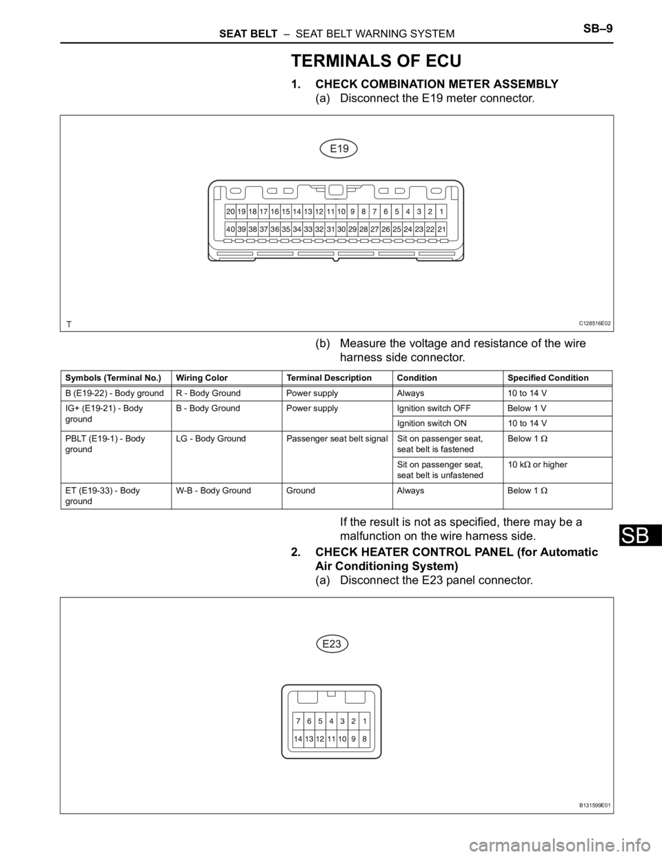
1. CHECK COMBINATION METER ASSEMBLY
(a) Disconnect the E19 meter connector.
(b) Measure the voltage and resistance of the wire
harness side connector.
If the result is not as specified, there may be a
malfunction on the wire harness side.
2. CHECK HEATER CONTROL PANEL (for Automatic
Air Conditioning System)
(a) Disconnect the E23 panel connector.
C128516E02
Symbols (Terminal No.) Wiring Color Terminal Description ConditionSpecified Condition
B (E19-22) - Body ground R - Body Ground Power supply Always 10 to 14 V
IG+ (E19-21) - Body
groundB - Body Ground Power supply Ignition switch OFF Below 1 V
Ignition switch ON 10 to 14 V
PBLT (E19-1) - Body
groundLG - Body Ground Passenger seat belt signal Sit on passenger seat,
seat belt is fastenedBelow 1
Sit on passenger seat,
seat belt is unfastened10 k or higher
ET (E19-33) - Body
groundW-B - Body Ground Ground Always Below 1
B131599E01
Page 1748 of 2000
SB–10SEAT BELT – SEAT BELT WARNING SYSTEM
SB
(b) Measure the voltage and resistance of the wire
harness side connector.
If the result is not as specified, there may be a
malfunction on the wire harness side.
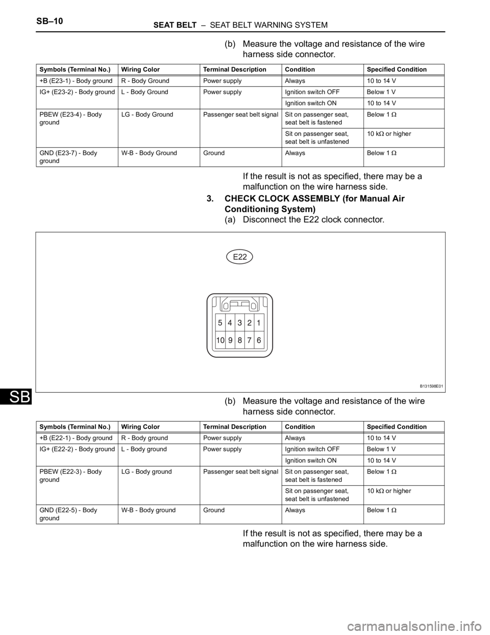
3. CHECK CLOCK ASSEMBLY (for Manual Air
Conditioning System)
(a) Disconnect the E22 clock connector.
(b) Measure the voltage and resistance of the wire
harness side connector.
If the result is not as specified, there may be a
malfunction on the wire harness side.
Symbols (Terminal No.) Wiring Color Terminal Description ConditionSpecified Condition
+B (E23-1) - Body ground R - Body Ground Power supply Always 10 to 14 V
IG+ (E23-2) - Body ground L - Body Ground Power supply Ignition switch OFF Below 1 V
Ignition switch ON 10 to 14 V
PBEW (E23-4) - Body
groundLG - Body Ground Passenger seat belt signal Sit on passenger seat,
seat belt is fastenedBelow 1
Sit on passenger seat,
seat belt is unfastened10 k or higher
GND (E23-7) - Body
groundW-B - Body Ground Ground Always Below 1
B131598E01
Symbols (Terminal No.) Wiring Color Terminal Description ConditionSpecified Condition
+B (E22-1) - Body ground R - Body ground Power supply Always 10 to 14 V
IG+ (E22-2) - Body ground L - Body ground Power supply Ignition switch OFF Below 1 V
Ignition switch ON 10 to 14 V
PBEW (E22-3) - Body
groundLG - Body ground Passenger seat belt signal Sit on passenger seat,
seat belt is fastenedBelow 1
Sit on passenger seat,
seat belt is unfastened10 k or higher
GND (E22-5) - Body
groundW-B - Body ground Ground Always Below 1
Page 1749 of 2000
SEAT BELT – SEAT BELT WARNING SYSTEMSB–11
SB
DIAGNOSIS SYSTEM
1. DESCRIPTION
(a) Data of the system can be read through the Data
Link Connector 3 (DLC3) of the vehicle.
Therefore, when the system seems to be
malfunctioning, use the intelligent tester to check for
a malfunction and repair it.
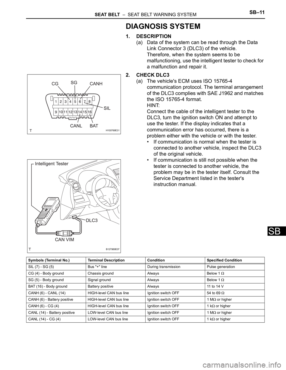
2. CHECK DLC3
(a) The vehicle's ECM uses ISO 15765-4
communication protocol. The terminal arrangement
of the DLC3 complies with SAE J1962 and matches
the ISO 15765-4 format.
HINT:
Connect the cable of the intelligent tester to the
DLC3, turn the ignition switch ON and attempt to
use the tester. If the display indicates that a
communication error has occurred, there is a
problem either with the vehicle or with the tester.
• If communication is normal when the tester is
connected to another vehicle, inspect the DLC3
of the original vehicle.
• If communication is still not possible when the
tester is connected to another vehicle, the
problem may be in the tester itself. Consult the
Service Department listed in the tester's
instruction manual.
H100769E31
B127989E07
Symbols (Terminal No.) Terminal Description Condition Specified Condition
SIL (7) - SG (5) Bus "+" line During transmission Pulse generation
CG (4) - Body ground Chassis ground Always Below 1
SG (5) - Body ground Signal ground Always Below 1
BAT (16) - Body ground Battery positive Always 11 to 14 V
CANH (6) - CANL (14) HIGH-level CAN bus line Ignition switch OFF 54 to 69
CANH (6) - Battery positive HIGH-level CAN bus line Ignition switch OFF 1 M or higher
CANH (6) - CG (4) HIGH-level CAN bus line Ignition switch OFF 1 k
or higher
CANL (14) - Battery positive LOW-level CAN bus line Ignition switch OFF 1 M
or higher
CANL (14) - CG (4) LOW-level CAN bus line Ignition switch OFF 1 k
or higher
Page 1750 of 2000

SB–12SEAT BELT – SEAT BELT WARNING SYSTEM
SB
DATA LIST / ACTIVE TEST
1. ACTIVE TEST
HINT:
Performing the intelligent tester ACTIVE TEST allows
relay, VSV, actuator and other items to be operated
without removing any parts. Performing the ACTIVE
TEST early in troubleshooting is one way to save time.
The DATA LIST can be displayed during the ACTIVE
TEST.
(a) Connect the intelligent tester to the DLC3.
(b) Turn the ignition switch ON.
(c) Perform the ACTIVE TEST according to the display
on the tester.
Center airbag sensor:
Item Test Details Diagnostic Note
D-BELT REMIND D-SEAT BELT warning light (OFF / ON) Confirm that the vehicle is stopped, engine
idling
P-BELT REMIND P-SEAT BELT warning light (OFF / ON) Confirm that the vehicle is stopped, engine
idling