TOYOTA RAV4 2006 Service Repair Manual
Manufacturer: TOYOTA, Model Year: 2006, Model line: RAV4, Model: TOYOTA RAV4 2006Pages: 2000, PDF Size: 45.84 MB
Page 1731 of 2000
RS–82SUPPLEMENTAL RESTRAINT SYSTEM – AIRBAG SYSTEM
RS
DESCRIPTION
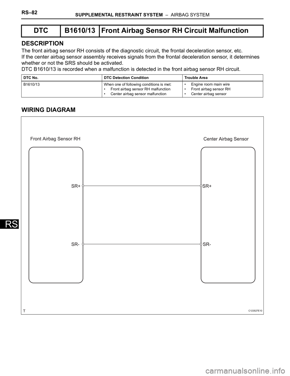
The front airbag sensor RH consists of the diagnostic circuit, the frontal deceleration sensor, etc.
If the center airbag sensor assembly receives signals from the frontal deceleration sensor, it determines
whether or not the SRS should be activated.
DTC B1610/13 is recorded when a malfunction is detected in the front airbag sensor RH circuit.
WIRING DIAGRAM
DTC B1610/13 Front Airbag Sensor RH Circuit Malfunction
DTC No. DTC Detection Condition Trouble Area
B1610/13 When one of following conditions is met:
• Front airbag sensor RH malfunction
• Center airbag sensor malfunction• Engine room main wire
• Front airbag sensor RH
• Center airbag sensor
C123527E10
Page 1732 of 2000
SUPPLEMENTAL RESTRAINT SYSTEM – AIRBAG SYSTEMRS–83
RS
INSPECTION PROCEDURE
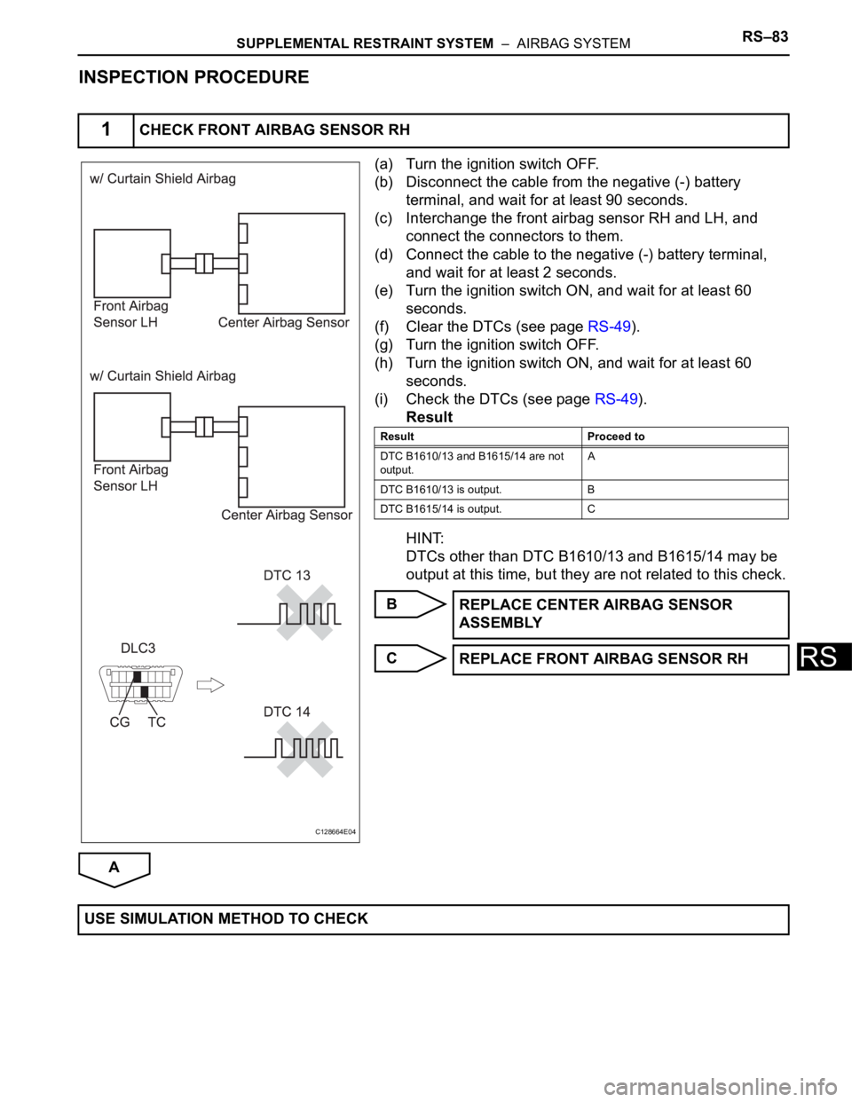
(a) Turn the ignition switch OFF.
(b) Disconnect the cable from the negative (-) battery
terminal, and wait for at least 90 seconds.
(c) Interchange the front airbag sensor RH and LH, and
connect the connectors to them.
(d) Connect the cable to the negative (-) battery terminal,
and wait for at least 2 seconds.
(e) Turn the ignition switch ON, and wait for at least 60
seconds.
(f) Clear the DTCs (see page RS-49).
(g) Turn the ignition switch OFF.
(h) Turn the ignition switch ON, and wait for at least 60
seconds.
(i) Check the DTCs (see page RS-49).
Result
HINT:
DTCs other than DTC B1610/13 and B1615/14 may be
output at this time, but they are not related to this check.
B
C
A
1CHECK FRONT AIRBAG SENSOR RH
C128664E04
Result Proceed to
DTC B1610/13 and B1615/14 are not
output.A
DTC B1610/13 is output. B
DTC B1615/14 is output. C
REPLACE CENTER AIRBAG SENSOR
ASSEMBLY
REPLACE FRONT AIRBAG SENSOR RH
USE SIMULATION METHOD TO CHECK
Page 1733 of 2000
RS–84SUPPLEMENTAL RESTRAINT SYSTEM – AIRBAG SYSTEM
RS
DESCRIPTION
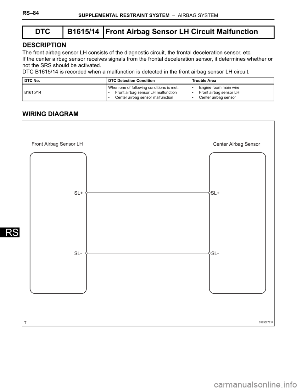
The front airbag sensor LH consists of the diagnostic circuit, the frontal deceleration sensor, etc.
If the center airbag sensor receives signals from the frontal deceleration sensor, it determines whether or
not the SRS should be activated.
DTC B1615/14 is recorded when a malfunction is detected in the front airbag sensor LH circuit.
WIRING DIAGRAM
DTC B1615/14 Front Airbag Sensor LH Circuit Malfunction
DTC No. DTC Detection Condition Trouble Area
B1615/14When one of following conditions is met:
• Front airbag sensor LH malfunction
• Center airbag sensor malfunction• Engine room main wire
• Front airbag sensor LH
• Center airbag sensor
C123527E11
Page 1734 of 2000
SUPPLEMENTAL RESTRAINT SYSTEM – AIRBAG SYSTEMRS–85
RS
INSPECTION PROCEDURE
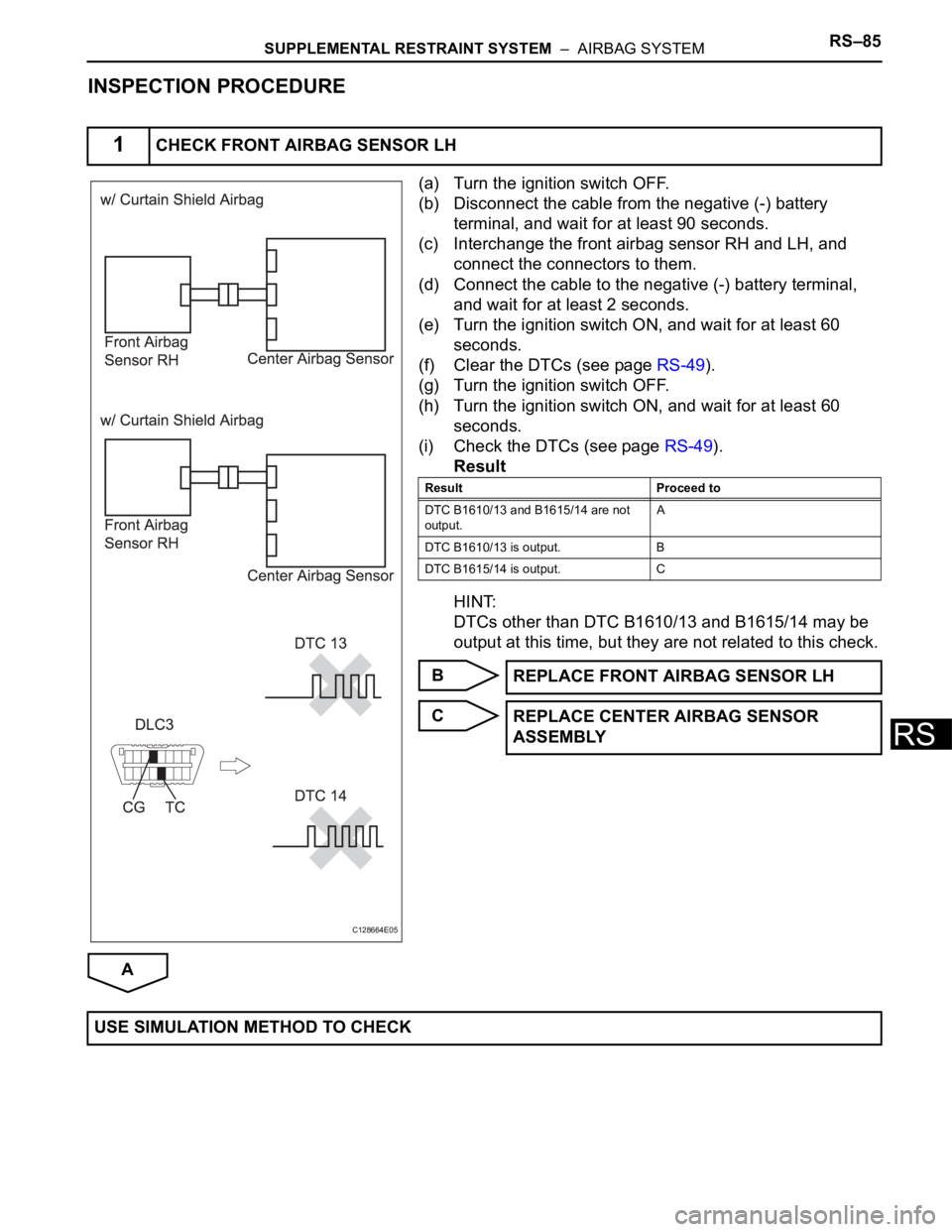
(a) Turn the ignition switch OFF.
(b) Disconnect the cable from the negative (-) battery
terminal, and wait for at least 90 seconds.
(c) Interchange the front airbag sensor RH and LH, and
connect the connectors to them.
(d) Connect the cable to the negative (-) battery terminal,
and wait for at least 2 seconds.
(e) Turn the ignition switch ON, and wait for at least 60
seconds.
(f) Clear the DTCs (see page RS-49).
(g) Turn the ignition switch OFF.
(h) Turn the ignition switch ON, and wait for at least 60
seconds.
(i) Check the DTCs (see page RS-49).
Result
HINT:
DTCs other than DTC B1610/13 and B1615/14 may be
output at this time, but they are not related to this check.
B
C
A
1CHECK FRONT AIRBAG SENSOR LH
C128664E05
Result Proceed to
DTC B1610/13 and B1615/14 are not
output.A
DTC B1610/13 is output. B
DTC B1615/14 is output. C
REPLACE FRONT AIRBAG SENSOR LH
REPLACE CENTER AIRBAG SENSOR
ASSEMBLY
USE SIMULATION METHOD TO CHECK
Page 1735 of 2000
RS–386SUPPLEMENTAL RESTRAINT SYSTEM – REAR AIRBAG SENSOR
RS
REMOVAL
HINT:
• Use the same procedures for the RH side and LH side.
• The procedures listed below are for the LH side.
CAUTION:
Be sure to read the precautionary notices concerning the
SRS airbag system before servicing it (see page RS-1).
1. DISCONNECT CABLE FROM NEGATIVE BATTERY
TERMINAL
CAUTION:
Wait at least 90 seconds after disconnecting the
cable from the negative (-) battery terminal to
prevent airbag and seat belt pretensioner activation.
2. REMOVE REAR DOOR SCUFF PLATE LH (See page
IR-26)
3. REMOVE REAR DOOR OPENING TRIM
WEATHERSTRIP LH
4. REMOVE PACKAGE TRAY TRIM POCKET SUB-
ASSEMBLY (w/o Rear No. 2 Seat)
5. REMOVE TONNEAU COVER ASSEMBLY (w/o Rear
No. 2 Seat)
6. REMOVE REAR FLOOR NO. 1 BOARD (w/o Rear No.
2 Seat)
7. REMOVE DECK BOARD ASSEMBLY (w/o Rear No. 2
Seat)
8. REMOVE NO. 2 SEAT HINGE COVER LH (w/ Rear No.
2 Seat) (See page SE-109)
9. REMOVE NO. 2 SEAT HINGE COVER RH (w/ Rear No.
2 Seat) (See page IR-30)
10. REMOVE NO. 2 SEAT LEG COVER LH (w/ Rear No. 2
Seat) (See page SE-109)
11. REMOVE NO. 2 SEAT LEG COVER RH (w/ Rear No. 2
Seat) (See page IR-30)
12. REMOVE REAR NO. 2 SEAT ASSEMBLY LH (w/ Rear
No. 2 Seat) (See page SE-110)
13. REMOVE REAR NO. 2 SEAT ASSEMBLY RH (w/ Rear
No. 2 Seat) (See page SE-110)
14. REMOVE REAR FLOOR NO. 2 BOARD
15. REMOVE REAR FLOOR NO. 3 BOARD
16. REMOVE REAR NO. 1 FLOOR MAT SUPPORT SIDE
PLATE (See page IR-31)
17. REMOVE BACK DOOR WEATHERSTRIP
18. REMOVE REAR FLOOR FINISH PLATE
19. REMOVE REAR DECK TRIM COVER (w/ Rear No. 2
Seat)
Page 1736 of 2000
SUPPLEMENTAL RESTRAINT SYSTEM – REAR AIRBAG SENSORRS–387
RS
20. REMOVE RECLINING REMOTE CONTROL LEVER
BEZEL LH (w/o Rear No. 2 Seat)
21. DISCONNECT REAR NO. 1 SEAT OUTER BELT
ASSEMBLY LH (See page SB-48)
22. DISCONNECT REAR NO. 2 SEAT OUTER BELT
ASSEMBLY LH (w/ Rear No. 2 Seat) (See page SB-48)
23. REMOVE DECK TRIM SIDE PANEL ASSEMBLY LH
(w/o Rear No. 2 Seat) (See page IR-32)
24. REMOVE DECK TRIM SIDE PANEL ASSEMBLY LH
(w/ Rear No. 2 Seat) (See page IR-32)
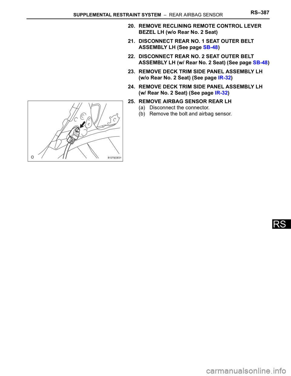
25. REMOVE AIRBAG SENSOR REAR LH
(a) Disconnect the connector.
(b) Remove the bolt and airbag sensor.
B127923E01
Page 1737 of 2000
RS–388SUPPLEMENTAL RESTRAINT SYSTEM – REAR AIRBAG SENSOR
RS
INSTALLATION
HINT:
• Use the same procedures for the RH side and LH side.
• The procedures listed below are for the LH side.
CAUTION:
Be sure to read the precautionary notices concerning the
SRS airbag system before servicing it (see page RS-1).
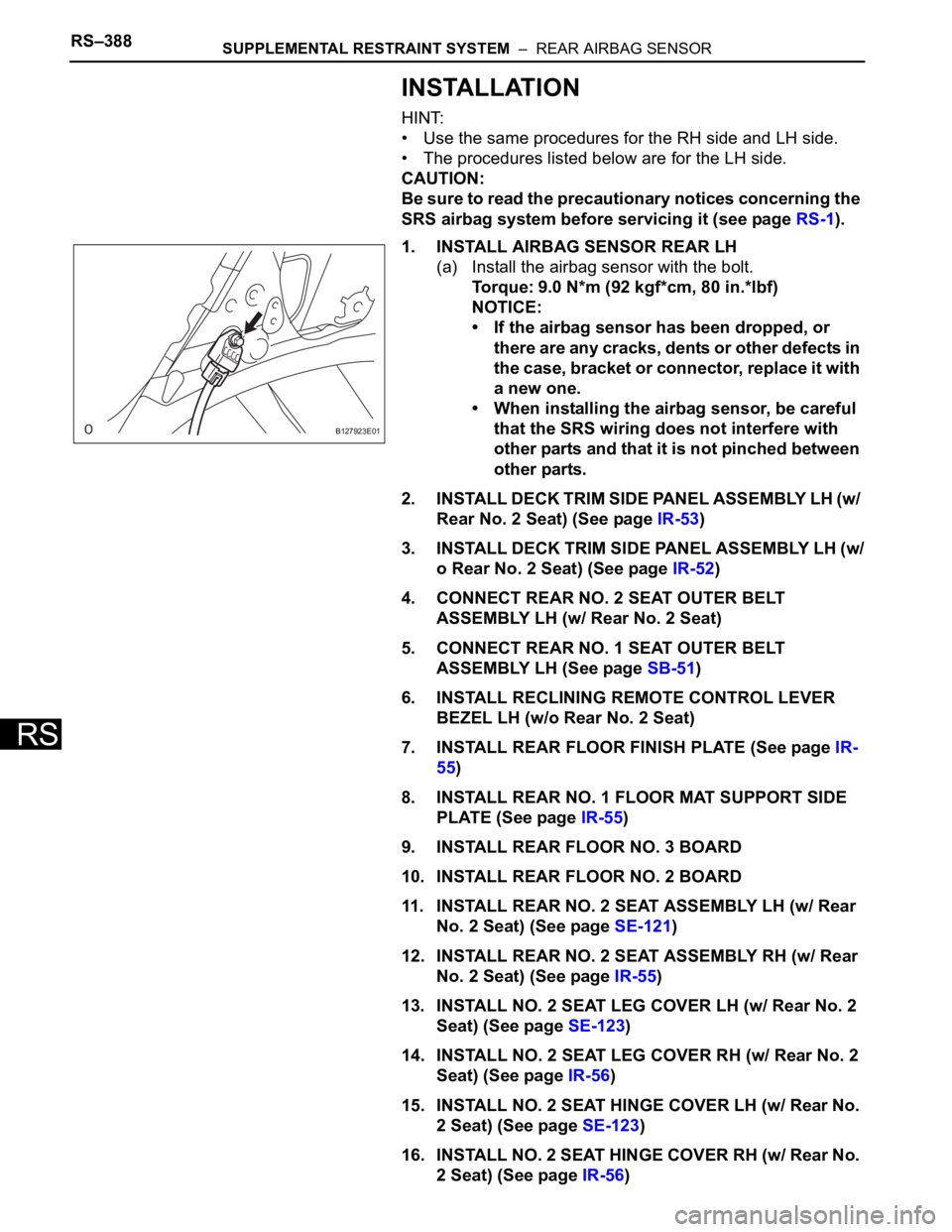
1. INSTALL AIRBAG SENSOR REAR LH
(a) Install the airbag sensor with the bolt.
Torque: 9.0 N*m (92 kgf*cm, 80 in.*lbf)
NOTICE:
• If the airbag sensor has been dropped, or
there are any cracks, dents or other defects in
the case, bracket or connector, replace it with
a new one.
• When installing the airbag sensor, be careful
that the SRS wiring does not interfere with
other parts and that it is not pinched between
other parts.
2. INSTALL DECK TRIM SIDE PANEL ASSEMBLY LH (w/
Rear No. 2 Seat) (See page IR-53)
3. INSTALL DECK TRIM SIDE PANEL ASSEMBLY LH (w/
o Rear No. 2 Seat) (See page IR-52)
4. CONNECT REAR NO. 2 SEAT OUTER BELT
ASSEMBLY LH (w/ Rear No. 2 Seat)
5. CONNECT REAR NO. 1 SEAT OUTER BELT
ASSEMBLY LH (See page SB-51)
6. INSTALL RECLINING REMOTE CONTROL LEVER
BEZEL LH (w/o Rear No. 2 Seat)
7. INSTALL REAR FLOOR FINISH PLATE (See page IR-
55)
8. INSTALL REAR NO. 1 FLOOR MAT SUPPORT SIDE
PLATE (See page IR-55)
9. INSTALL REAR FLOOR NO. 3 BOARD
10. INSTALL REAR FLOOR NO. 2 BOARD
11. INSTALL REAR NO. 2 SEAT ASSEMBLY LH (w/ Rear
No. 2 Seat) (See page SE-121)
12. INSTALL REAR NO. 2 SEAT ASSEMBLY RH (w/ Rear
No. 2 Seat) (See page IR-55)
13. INSTALL NO. 2 SEAT LEG COVER LH (w/ Rear No. 2
Seat) (See page SE-123)
14. INSTALL NO. 2 SEAT LEG COVER RH (w/ Rear No. 2
Seat) (See page IR-56)
15. INSTALL NO. 2 SEAT HINGE COVER LH (w/ Rear No.
2 Seat) (See page SE-123)
16. INSTALL NO. 2 SEAT HINGE COVER RH (w/ Rear No.
2 Seat) (See page IR-56)
B127923E01
Page 1738 of 2000
SUPPLEMENTAL RESTRAINT SYSTEM – REAR AIRBAG SENSORRS–389
RS
17. INSTALL DECK BOARD ASSEMBLY (w/o Rear No. 2
Seat)
18. INSTALL REAR FLOOR NO. 1 BOARD (w/o Rear No.
2 Seat)
19. INSTALL TONNEAU COVER ASSEMBLY (w/o Rear
No. 2 Seat)
20. REMOVE PACKAGE TRAY TRIM POCKET SUB-
ASSEMBLY (w/o Rear No. 2 Seat)
21. INSTALL REAR DOOR OPENING TRIM
WEATHERSTRIP LH
22. INSTALL REAR DOOR SCUFF PLATE LH (See page
IR-57)
23. CONNECT CABLE TO NEGATIVE BATTERY
TERMINAL
24. CHECK SRS WARNING LIGHT
(a) Check the SRS warning light (see page RS-34).
Page 1739 of 2000
SUPPLEMENTAL RESTRAINT SYSTEM – SEAT POSITION SENSORRS–391
RS
REMOVAL
CAUTION:
Be sure to read the precautionary notices concerning the
SRS airbag system before servicing it (see page RS-1).
1. DISCONNECT CABLE FROM NEGATIVE BATTERY
TERMINAL
CAUTION:
Wait at least 90 seconds after disconnecting the
cable from the negative (-) battery terminal to
prevent airbag and seat belt pretensioner activation.
2. REMOVE FRONT SEAT ASSEMBLY (for Manual Seat)
(See page SE-11)
3. REMOVE FRONT SEAT ASSEMBLY (for Power Seat)
(See page SE-27)
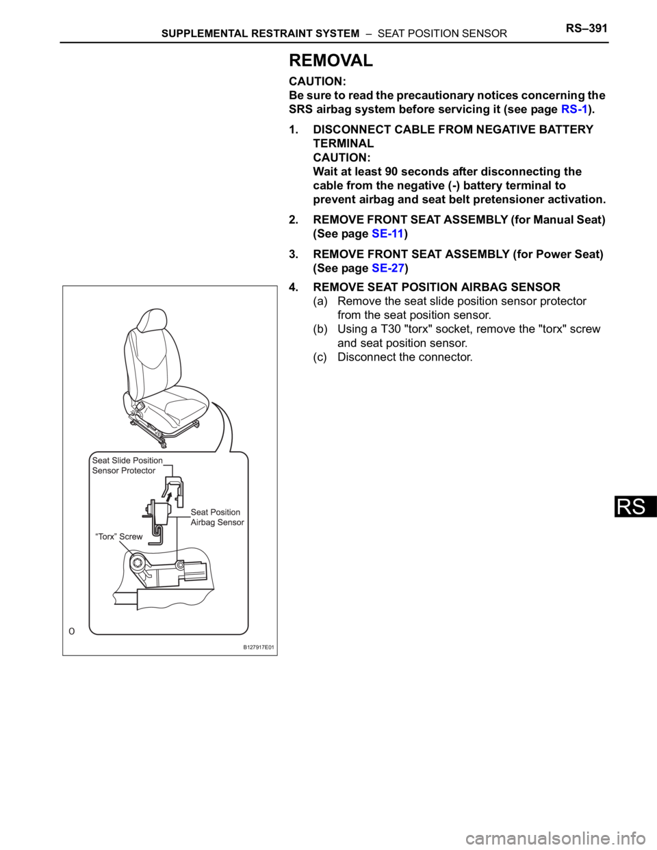
4. REMOVE SEAT POSITION AIRBAG SENSOR
(a) Remove the seat slide position sensor protector
from the seat position sensor.
(b) Using a T30 "torx" socket, remove the "torx" screw
and seat position sensor.
(c) Disconnect the connector.
B127917E01
Page 1740 of 2000
RS–392SUPPLEMENTAL RESTRAINT SYSTEM – SEAT POSITION SENSOR
RS
INSTALLATION
CAUTION:
Be sure to read the precautionary notices concerning the
SRS airbag system before servicing it (see page RS-1).
1. INSTALL SEAT POSITION AIRBAG SENSOR
(a) Using a 1 mm (0.039 in.) feeler gauge, install the
seat position sensor.
NOTICE:
• If the seat position sensor has been dropped,
or there are any cracks, dents or other
defects in the case or connector, replace the
seat position sensor with a new one.
• When installing the seat position sensor, be
careful that the SRS wiring does not interfere
with other parts and that it is not pinched
between other parts.
HINT:
Be sure that the clearance between the seat
position sensor and the seat rail is within 0.6 mm to
1.4 mm (0.023 to 0.055 in.).
(b) Using a T30 "torx" socket, tighten the "torx" screw to
install the seat position sensor.
Torque: 8.0 N*m (82 kgf*cm, 71 in.*lbf)
(c) Make sure that the clearance between the seat
position sensor and the seat rail is within 0.6 mm to
1.4 mm (0.023 to 0.055 in.).
(d) Connect the connector.