TOYOTA RAV4 2006 Service Repair Manual
Manufacturer: TOYOTA, Model Year: 2006, Model line: RAV4, Model: TOYOTA RAV4 2006Pages: 2000, PDF Size: 45.84 MB
Page 1791 of 2000
EI–20ENGINE IMMOBILISER – ENGINE IMMOBILISER SYSTEM
EI
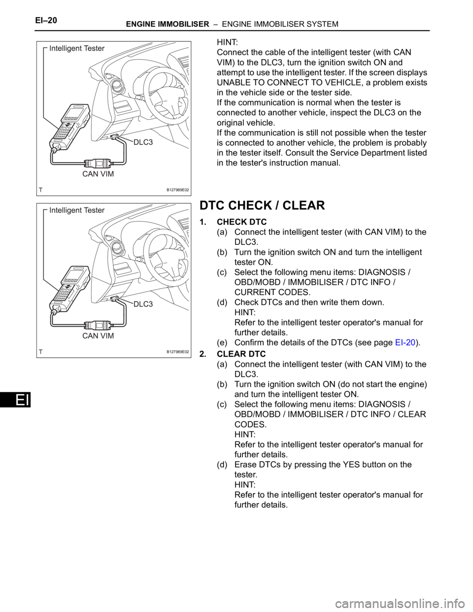
HINT:
Connect the cable of the intelligent tester (with CAN
VIM) to the DLC3, turn the ignition switch ON and
attempt to use the intelligent tester. If the screen displays
UNABLE TO CONNECT TO VEHICLE, a problem exists
in the vehicle side or the tester side.
If the communication is normal when the tester is
connected to another vehicle, inspect the DLC3 on the
original vehicle.
If the communication is still not possible when the tester
is connected to another vehicle, the problem is probably
in the tester itself. Consult the Service Department listed
in the tester's instruction manual.
DTC CHECK / CLEAR
1. CHECK DTC
(a) Connect the intelligent tester (with CAN VIM) to the
DLC3.
(b) Turn the ignition switch ON and turn the intelligent
tester ON.
(c) Select the following menu items: DIAGNOSIS /
OBD/MOBD / IMMOBILISER / DTC INFO /
CURRENT CODES.
(d) Check DTCs and then write them down.
HINT:
Refer to the intelligent tester operator's manual for
further details.
(e) Confirm the details of the DTCs (see page EI-20).
2. CLEAR DTC
(a) Connect the intelligent tester (with CAN VIM) to the
DLC3.
(b) Turn the ignition switch ON (do not start the engine)
and turn the intelligent tester ON.
(c) Select the following menu items: DIAGNOSIS /
OBD/MOBD / IMMOBILISER / DTC INFO / CLEAR
CODES.
HINT:
Refer to the intelligent tester operator's manual for
further details.
(d) Erase DTCs by pressing the YES button on the
tester.
HINT:
Refer to the intelligent tester operator's manual for
further details.
B127989E02
B127989E02
Page 1792 of 2000

ENGINE IMMOBILISER – ENGINE IMMOBILISER SYSTEMEI–21
EI
DATA LIST / ACTIVE TEST
1. READ DATA LIST
HINT:
Using the intelligent tester's DATA LIST allows switch,
sensor, actuator and other item values to be read without
removing any parts. Reading the DATA LIST early in
troubleshooting is one way to save time.
(a) Connect the intelligent tester (with CAN VIM) to the
DLC3.
(b) Turn the ignition switch ON and turn the tester ON.
(c) Select the following menu items: DIAGNOSIS /
OBD/MOBD / IMMOBILISER / DATA LIST.
(d) Check the results by referring to the table below.
Transponder key ECU:
ItemMeasurement Item / Display
(Range)Normal Condition Diagnostic Note
KEY SWUnlock warning switch signal /
ON or OFFON: Key is in ignition key cylinder
OFF: No key is in ignition key
cylinder-
IG SW Ignition switch signal / ON or OFFON: Ignition switch ON (IG or
ACC)
OFF: Ignition switch OFF-
IMMOBILISERImmobiliser system status / SET
or UNSETSET: No key is in ignition key
cylinder
UNSET: Key is in ignition key
cylinder-
PERMIT (START)Engine starting control / OK or
NGOK: Engine start is permitted
NG: Engine start is not permitted-
RESPONSETransponder chip data / NG or
OKNG: Data error
OK: Data OK-
FRAME ERRORTransponder chip data / NG or
OKNG: Data error
OK: Data OK-
SERIAL NUMBERTransponder chip data / NG or
OKNG: Data error
OK: Data OK-
ENCRYPT CODETransponder chip data / NG or
OKNG: Data error
OK: Data OK-
STATUSTransponder chip data / NG or
OKNG: Data error
OK: Data OK-
BCCTransponder chip signal / NG or
OKNG: Incorrect data sent
OK: Correct data sent-
SUB KEYSub-key code signal / MATCH or
NOMATCHMATCH: Registered sub-key
code is sent
NOMATCH: Unmatched sub-key
code is sent-
MASTER KEYMaster key code signal / MATCH
or NOMATCHMATCH: Registered master key
code is sent
NOMATCH: Unmatched master
key code is sent-
REGIST SUB CODENumber of registered sub-keys /
min.: 0, max.: 15Number of registered sub-keys -
REGIST MAS CODENumber of registered master
keys / min.: 0, max.: 15Number of registered master
keys-
REG CODE SPACEKey registration code memory
space full / NOTFULL or FULLNOTFULL: Possible to register
more key codes
FULL: Cannot register any more
key codes-
Page 1793 of 2000

EI–22ENGINE IMMOBILISER – ENGINE IMMOBILISER SYSTEM
EI
2. PERFORM ACTIVE TEST
HINT:
Performing the intelligent tester's ACTIVE TEST allows
relay, VSV, actuator and other items to be operated
without removing any parts. Performing the ACTIVE
TEST early in troubleshooting is one way to save time.
The DATA LIST can be displayed during the ACTIVE
TEST.
(a) Connect the intelligent tester (with CAN VIM) to the
DLC3.
(b) Turn the ignition switch ON and turn the tester ON.
(c) Select the following menu items: DIAGNOSIS /
OBD/MOBD / IMMOBILISER / ACTIVE TEST.
(d) Perform the ACTIVE TEST by referring to the table
below.
Transponder key ECU:
+B+B judgment / NORMAL or
BREAKNORMAL: Battery supply is
normal
BREAK: Battery supply is
malfunctioning-
ANTENNA COILTransponder key coil condition /
NORMAL or FAILNORMAL: Transponder key coil
is normal
FAIL: Transponder key coil is
malfunctioning- ItemMeasurement Item / Display
(Range)Normal Condition Diagnostic Note
Item Test Details Diagnostic Note
SECURITY INDIC Turns security indicator light / ON or OFF -
Page 1794 of 2000

ENGINE IMMOBILISER – ENGINE IMMOBILISER SYSTEMEI–23
EI
DIAGNOSTIC TROUBLE CODE CHART
Transponder key ECU:
ECM:
DTC No. Detection Item Trouble Area See page
B2780Push Switch / Key Unlock
Warning Switch Malfunction- Transponder key ECU
- Unlock warning switch
- Wire harnessEI-21
B2784Antenna Coil Open / Short - Transponder key ECU
- Transponder key amplifier
- Wire harnessEI-24
B2793 Transponder Chip Malfunction KeyEI-26
B2794 Unmatched Encryption Code KeyEI-27
B2795 Unmatched Key Code KeyEI-28
B2796No Communication in Immobiliser
System- Transponder key ECU
- Key
- Wire harness
- Transponder key amplifierEI-29
B2797Communication Malfunction No. 1 - Key
- Wire harness
- Transponder key ECU
- Transponder key amplifierEI-32
B2798 Communication Malfunction No. 2 KeyEI-29
DTC No. Detection Item Trouble Area See page
B2799Engine Immobiliser System - Wire harness
- Transponder key ECU
- ECMEI-36
Page 1795 of 2000
EI–24ENGINE IMMOBILISER – ENGINE IMMOBILISER SYSTEM
EI
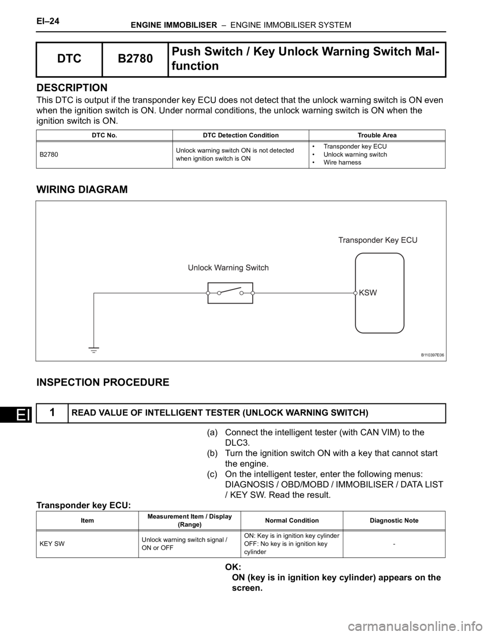
DESCRIPTION
This DTC is output if the transponder key ECU does not detect that the unlock warning switch is ON even
when the ignition switch is ON. Under normal conditions, the unlock warning switch is ON when the
ignition switch is ON.
WIRING DIAGRAM
INSPECTION PROCEDURE
(a) Connect the intelligent tester (with CAN VIM) to the
DLC3.
(b) Turn the ignition switch ON with a key that cannot start
the engine.
(c) On the intelligent tester, enter the following menus:
DIAGNOSIS / OBD/MOBD / IMMOBILISER / DATA LIST
/ KEY SW. Read the result.
Transponder key ECU:
OK:
ON (key is in ignition key cylinder) appears on the
screen.
DTC B2780Push Switch / Key Unlock Warning Switch Mal-
function
DTC No. DTC Detection Condition Trouble Area
B2780Unlock warning switch ON is not detected
when ignition switch is ON• Transponder key ECU
• Unlock warning switch
• Wire harness
1READ VALUE OF INTELLIGENT TESTER (UNLOCK WARNING SWITCH)
B110397E06
ItemMeasurement Item / Display
(Range)Normal Condition Diagnostic Note
KEY SWUnlock warning switch signal /
ON or OFFON: Key is in ignition key cylinder
OFF: No key is in ignition key
cylinder-
Page 1796 of 2000
ENGINE IMMOBILISER – ENGINE IMMOBILISER SYSTEMEI–25
EI
OK
NG
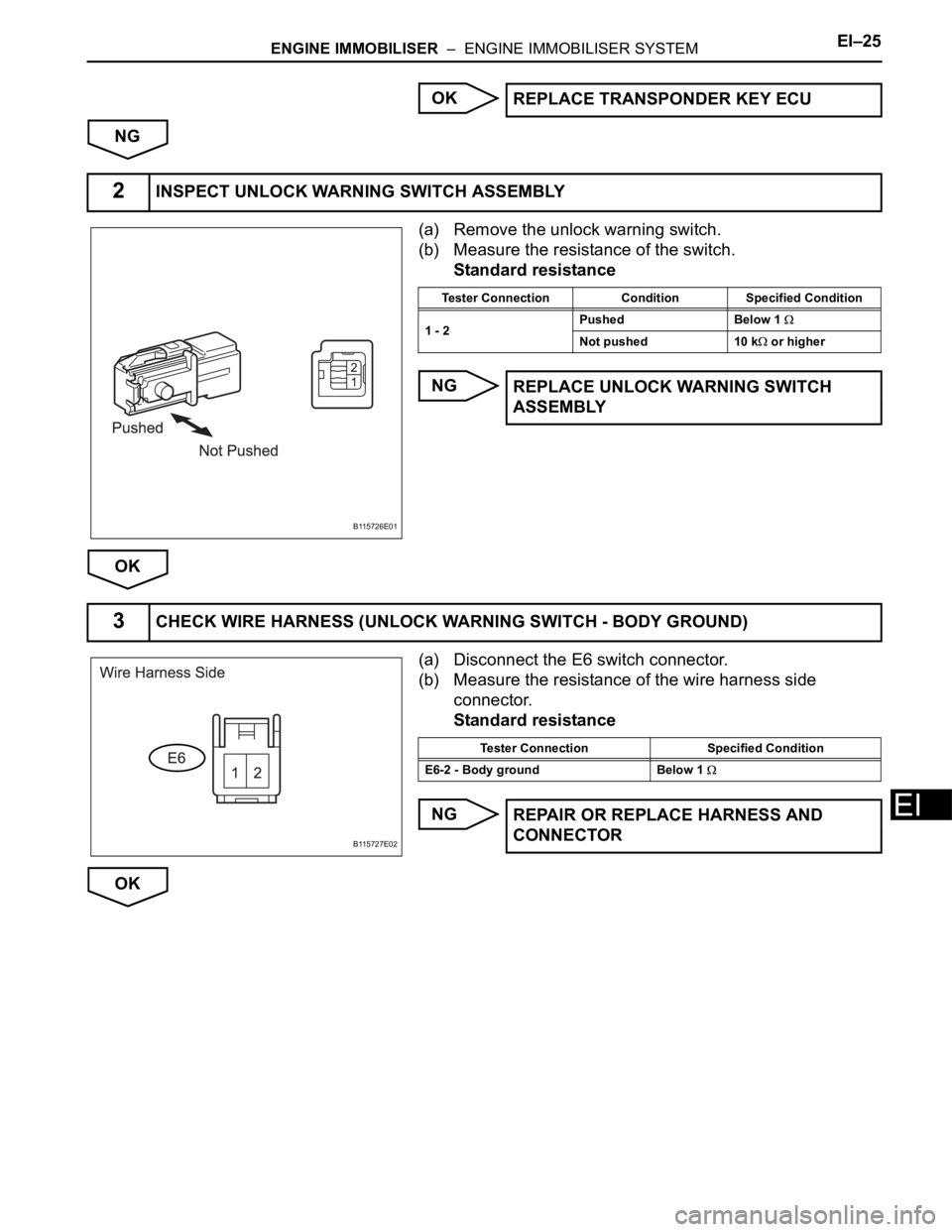
(a) Remove the unlock warning switch.
(b) Measure the resistance of the switch.
Standard resistance
NG
OK
(a) Disconnect the E6 switch connector.
(b) Measure the resistance of the wire harness side
connector.
Standard resistance
NG
OKREPLACE TRANSPONDER KEY ECU
2INSPECT UNLOCK WARNING SWITCH ASSEMBLY
B115726E01
Tester Connection Condition Specified Condition
1 - 2Pushed Below 1
Not pushed 10 k or higher
REPLACE UNLOCK WARNING SWITCH
ASSEMBLY
3CHECK WIRE HARNESS (UNLOCK WARNING SWITCH - BODY GROUND)
B115727E02
Tester Connection Specified Condition
E6-2 - Body ground Below 1
REPAIR OR REPLACE HARNESS AND
CONNECTOR
Page 1797 of 2000
EI–26ENGINE IMMOBILISER – ENGINE IMMOBILISER SYSTEM
EI
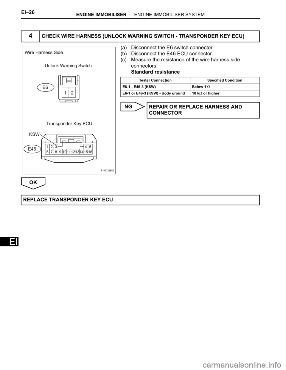
(a) Disconnect the E6 switch connector.
(b) Disconnect the E46 ECU connector.
(c) Measure the resistance of the wire harness side
connectors.
Standard resistance
NG
OK
4CHECK WIRE HARNESS (UNLOCK WARNING SWITCH - TRANSPONDER KEY ECU)
B115728E02
Tester Connection Specified Condition
E6-1 - E46-3 (KSW) Below 1
E6-1 or E46-3 (KSW) - Body ground 10 k or higher
REPAIR OR REPLACE HARNESS AND
CONNECTOR
REPLACE TRANSPONDER KEY ECU
Page 1798 of 2000
ENGINE IMMOBILISER – ENGINE IMMOBILISER SYSTEMEI–27
EI
DESCRIPTION
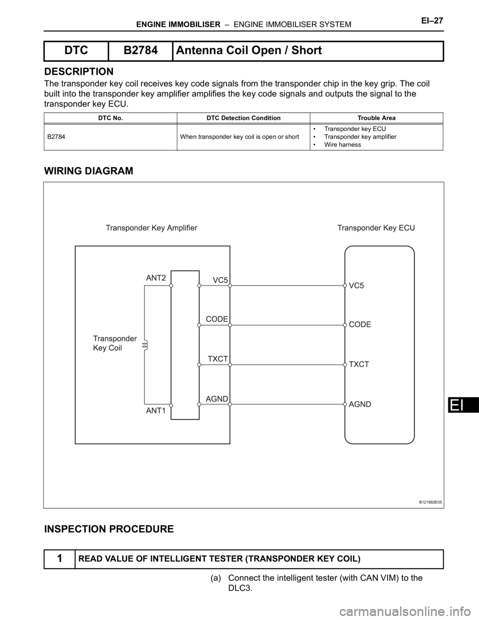
The transponder key coil receives key code signals from the transponder chip in the key grip. The coil
built into the transponder key amplifier amplifies the key code signals and outputs the signal to the
transponder key ECU.
WIRING DIAGRAM
INSPECTION PROCEDURE
(a) Connect the intelligent tester (with CAN VIM) to the
DLC3.
DTC B2784 Antenna Coil Open / Short
DTC No. DTC Detection Condition Trouble Area
B2784 When transponder key coil is open or short• Transponder key ECU
• Transponder key amplifier
• Wire harness
1READ VALUE OF INTELLIGENT TESTER (TRANSPONDER KEY COIL)
B121682E05
Page 1799 of 2000
EI–28ENGINE IMMOBILISER – ENGINE IMMOBILISER SYSTEM
EI
(b) Turn the ignition switch ON with a key that cannot start
the engine.
(c) On the intelligent tester, enter the following menus:
DIAGNOSIS / OBD/MOBD / IMMOBILISER / DATA LIST
/ ANTENNA COIL. Read the result.
Transponder key ECU:
OK:
NORMAL (Transponder key coil is normal) appears
on the screen.
OK
NG
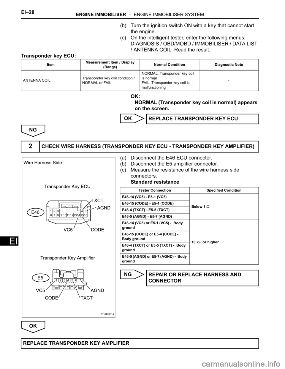
(a) Disconnect the E46 ECU connector.
(b) Disconnect the E5 amplifier connector.
(c) Measure the resistance of the wire harness side
connectors.
Standard resistance
NG
OK
ItemMeasurement Item / Display
(Range)Normal Condition Diagnostic Note
ANTENNA COILTransponder key coil condition /
NORMAL or FAILNORMAL: Transponder key coil
is normal
FAIL: Transponder key coil is
malfunctioning-
REPLACE TRANSPONDER KEY ECU
2CHECK WIRE HARNESS (TRANSPONDER KEY ECU - TRANSPONDER KEY AMPLIFIER)
B110403E14
Tester Connection Specified Condition
E46-14 (VC5) - E5-1 (VC5)
Below 1
E46-15 (CODE) - E5-4 (CODE)
E46-4 (TXCT) - E5-5 (TXCT)
E46-5 (AGND) - E5-7 (AGND)
E46-14 (VC5) or E5-1 (VC5) - Body
ground
10 k
or higher E46-15 (CODE) or E5-4 (CODE) -
Body ground
E46-4 (TXCT) or E5-5 (TXCT) - Body
ground
E46-5 (AGND) or E5-7 (AGND) - Body
ground
REPAIR OR REPLACE HARNESS AND
CONNECTOR
REPLACE TRANSPONDER KEY AMPLIFIER
Page 1800 of 2000
ENGINE IMMOBILISER – ENGINE IMMOBILISER SYSTEMEI–29
EI
DESCRIPTION
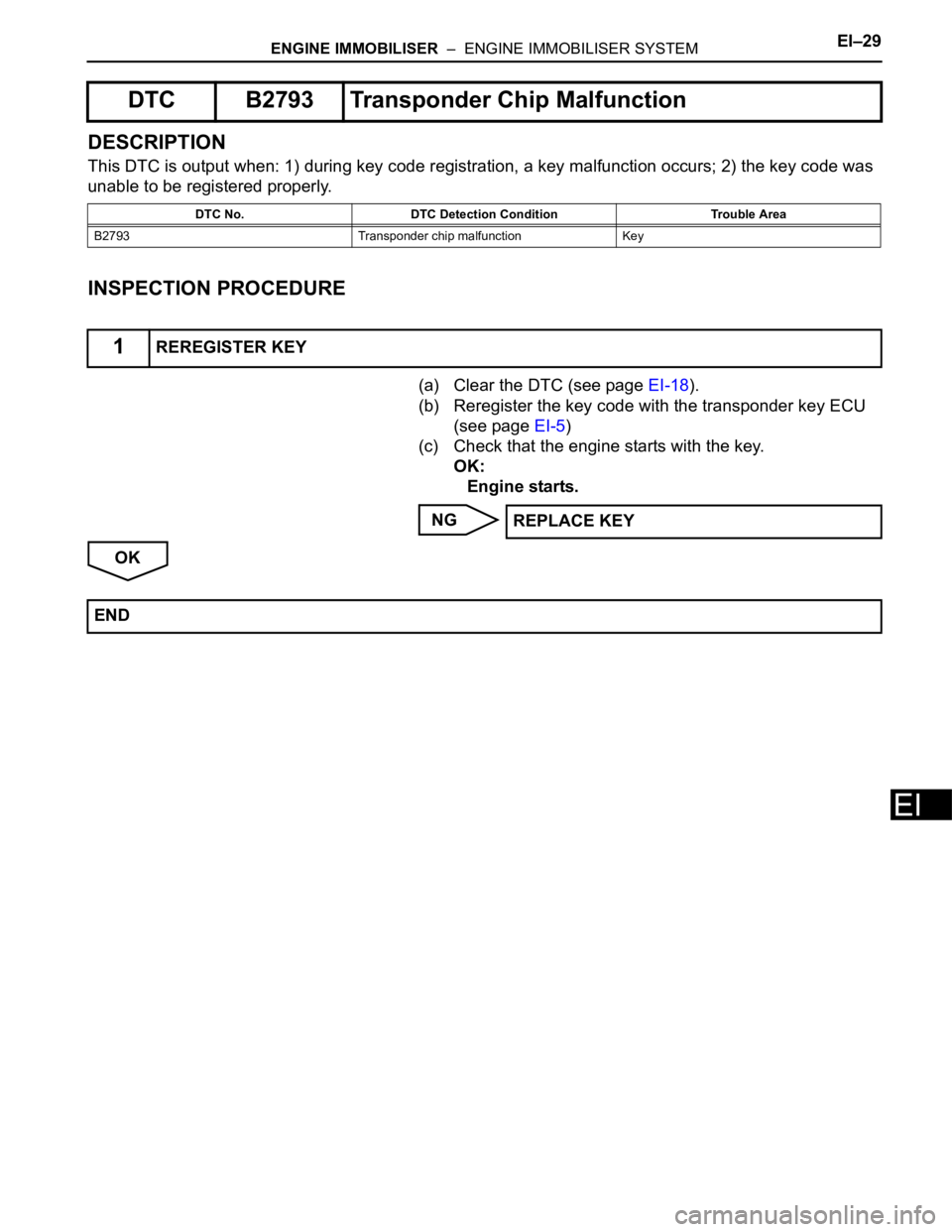
This DTC is output when: 1) during key code registration, a key malfunction occurs; 2) the key code was
unable to be registered properly.
INSPECTION PROCEDURE
(a) Clear the DTC (see page EI-18).
(b) Reregister the key code with the transponder key ECU
(see page EI-5)
(c) Check that the engine starts with the key.
OK:
Engine starts.
NG
OK
DTC B2793 Transponder Chip Malfunction
DTC No. DTC Detection Condition Trouble Area
B2793 Transponder chip malfunction Key
1REREGISTER KEY
REPLACE KEY
END