TOYOTA RAV4 2006 Service Repair Manual
Manufacturer: TOYOTA, Model Year: 2006, Model line: RAV4, Model: TOYOTA RAV4 2006Pages: 2000, PDF Size: 45.84 MB
Page 721 of 2000
EM–842GR-FE ENGINE MECHANICAL – ENGINE UNIT
EM
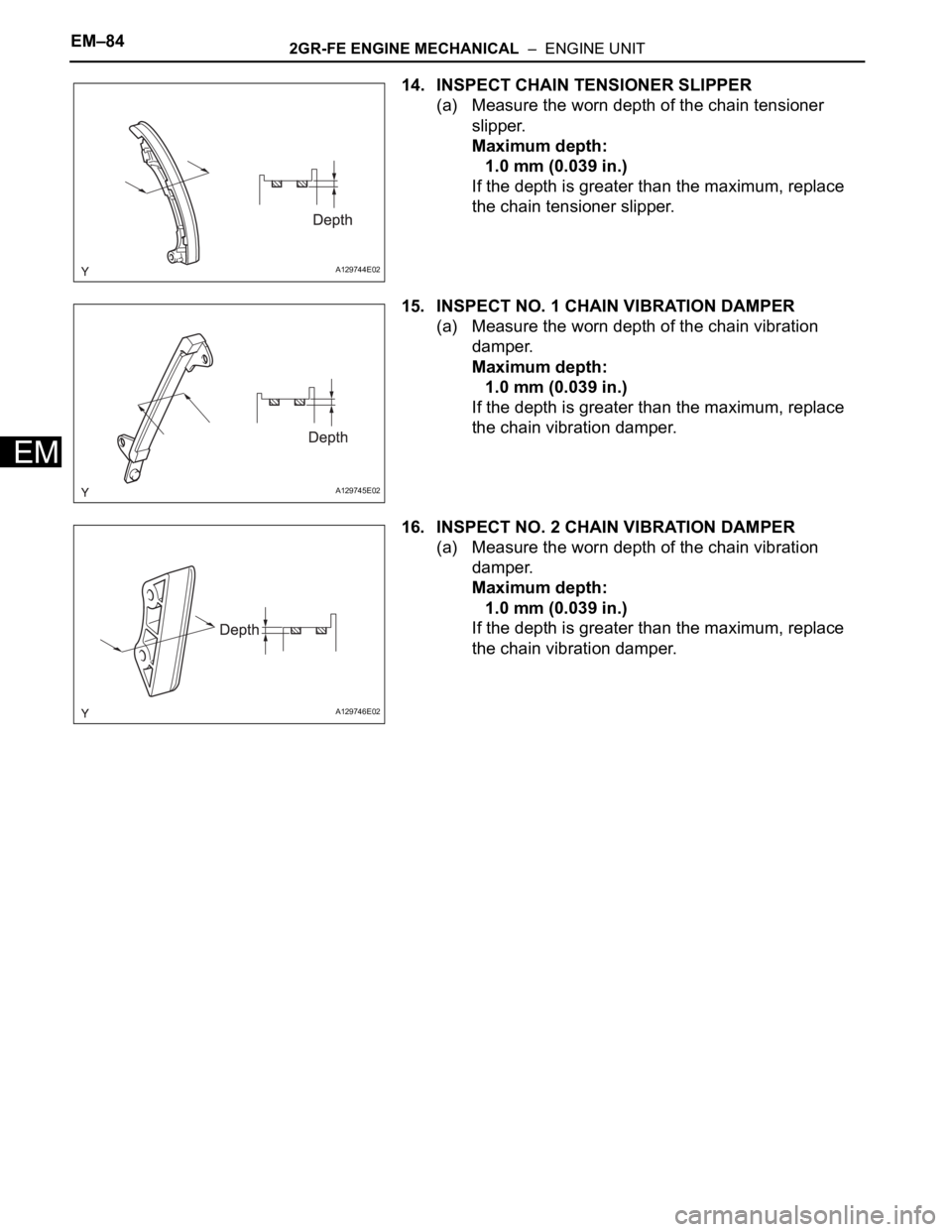
14. INSPECT CHAIN TENSIONER SLIPPER
(a) Measure the worn depth of the chain tensioner
slipper.
Maximum depth:
1.0 mm (0.039 in.)
If the depth is greater than the maximum, replace
the chain tensioner slipper.
15. INSPECT NO. 1 CHAIN VIBRATION DAMPER
(a) Measure the worn depth of the chain vibration
damper.
Maximum depth:
1.0 mm (0.039 in.)
If the depth is greater than the maximum, replace
the chain vibration damper.
16. INSPECT NO. 2 CHAIN VIBRATION DAMPER
(a) Measure the worn depth of the chain vibration
damper.
Maximum depth:
1.0 mm (0.039 in.)
If the depth is greater than the maximum, replace
the chain vibration damper.
A129744E02
A129745E02
A129746E02
Page 722 of 2000
2GR-FE ENGINE MECHANICAL – ENGINE UNITEM–85
EM
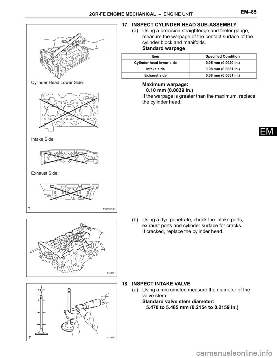
17. INSPECT CYLINDER HEAD SUB-ASSEMBLY
(a) Using a precision straightedge and feeler gauge,
measure the warpage of the contact surface of the
cylinder block and manifolds.
Standard warpage
Maximum warpage:
0.10 mm (0.0039 in.)
If the warpage is greater than the maximum, replace
the cylinder head.
(b) Using a dye penetrate, check the intake ports,
exhaust ports and cylinder surface for cracks.
If cracked, replace the cylinder head.
18. INSPECT INTAKE VALVE
(a) Using a micrometer, measure the diameter of the
valve stem.
Standard valve stem diameter:
5.470 to 5.485 mm (0.2154 to 0.2159 in.)
A132032E01
Item Specified Condition
Cylinder head lower side 0.05 mm (0.0020 in.)
Intake side 0.08 mm (0.0031 in.)
Exhaust side 0.08 mm (0.0031 in.)
A132151
A131997
Page 723 of 2000
EM–862GR-FE ENGINE MECHANICAL – ENGINE UNIT
EM
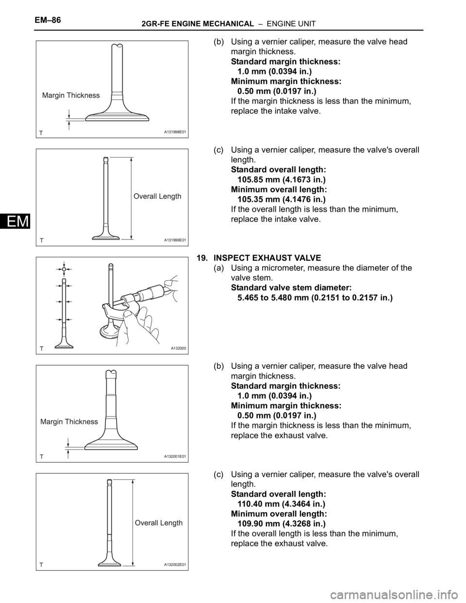
(b) Using a vernier caliper, measure the valve head
margin thickness.
Standard margin thickness:
1.0 mm (0.0394 in.)
Minimum margin thickness:
0.50 mm (0.0197 in.)
If the margin thickness is less than the minimum,
replace the intake valve.
(c) Using a vernier caliper, measure the valve's overall
length.
Standard overall length:
105.85 mm (4.1673 in.)
Minimum overall length:
105.35 mm (4.1476 in.)
If the overall length is less than the minimum,
replace the intake valve.
19. INSPECT EXHAUST VALVE
(a) Using a micrometer, measure the diameter of the
valve stem.
Standard valve stem diameter:
5.465 to 5.480 mm (0.2151 to 0.2157 in.)
(b) Using a vernier caliper, measure the valve head
margin thickness.
Standard margin thickness:
1.0 mm (0.0394 in.)
Minimum margin thickness:
0.50 mm (0.0197 in.)
If the margin thickness is less than the minimum,
replace the exhaust valve.
(c) Using a vernier caliper, measure the valve's overall
length.
Standard overall length:
110.40 mm (4.3464 in.)
Minimum overall length:
109.90 mm (4.3268 in.)
If the overall length is less than the minimum,
replace the exhaust valve.
A131998E01
A131999E01
A132000
A132001E01
A132002E01
Page 724 of 2000

2GR-FE ENGINE MECHANICAL – ENGINE UNITEM–87
EM
20. INSPECT INTAKE VALVE SEAT
(a) Apply a light coat of Prussian blue to the valve face.
(b) Lightly press the valve face against the valve seat.
(c) Check the valve face and valve seat by using the
following procedure.
(1) If Prussian blue appears around the entire
valve face, the valve face is concentric. If not,
replace the valve.
(2) If Prussian blue appears around the entire
valve seat, the guide and valve face are
concentric. If not, resurface the valve seat.
(3) Check that the valve seat contacts in the
middle of the valve face with the width between
1.1 and 1.5 mm (0.043 and 0.059 in.).
21. INSPECT EXHAUST VALVE SEAT
(a) Apply a light coat of Prussian blue to the valve face.
(b) Lightly press the valve face against the valve seat.
(c) Check the valve face and valve seat by using the
following procedure.
(1) If Prussian blue appears around the entire
valve face, the valve face is concentric. If not,
replace the valve.
(2) If Prussian blue appears around the entire
valve seat, the guide and valve face are
concentric. If not, resurface the valve seat.
(3) Check that the valve seat contacts in the
middle of the valve face with the width between
1.2 and 1.6 mm (0.047 and 0.063 in.).
22. INSPECT INNER COMPRESSION SPRING
(a) Using a vernier caliper, measure the free length of
the inner compression spring.
Standard free length:
45.46 mm (1.7898 in.)
If the free length is not as specified, replace the
spring.
(b) Using a steel square, measure the deviation of the
inner compression spring.
Maximum deviation:
1.0 mm (0.039 in.)
Maximum angle (reference):
2
If the deviation is greater than the maximum,
replace the spring.
A132152E01
A132152E01
A101392
A101393E02
Page 725 of 2000
EM–882GR-FE ENGINE MECHANICAL – ENGINE UNIT
EM
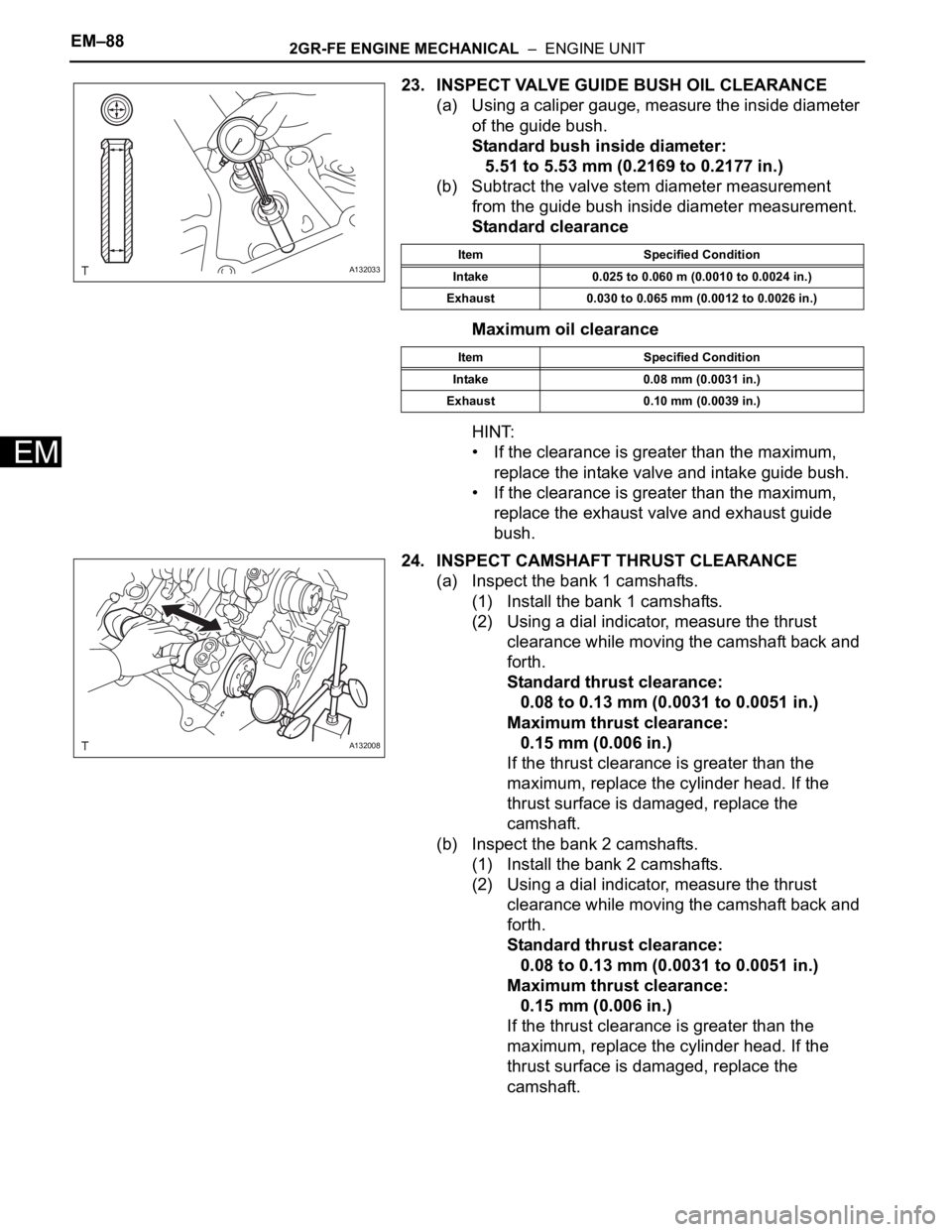
23. INSPECT VALVE GUIDE BUSH OIL CLEARANCE
(a) Using a caliper gauge, measure the inside diameter
of the guide bush.
Standard bush inside diameter:
5.51 to 5.53 mm (0.2169 to 0.2177 in.)
(b) Subtract the valve stem diameter measurement
from the guide bush inside diameter measurement.
Standard clearance
Maximum oil clearance
HINT:
• If the clearance is greater than the maximum,
replace the intake valve and intake guide bush.
• If the clearance is greater than the maximum,
replace the exhaust valve and exhaust guide
bush.
24. INSPECT CAMSHAFT THRUST CLEARANCE
(a) Inspect the bank 1 camshafts.
(1) Install the bank 1 camshafts.
(2) Using a dial indicator, measure the thrust
clearance while moving the camshaft back and
forth.
Standard thrust clearance:
0.08 to 0.13 mm (0.0031 to 0.0051 in.)
Maximum thrust clearance:
0.15 mm (0.006 in.)
If the thrust clearance is greater than the
maximum, replace the cylinder head. If the
thrust surface is damaged, replace the
camshaft.
(b) Inspect the bank 2 camshafts.
(1) Install the bank 2 camshafts.
(2) Using a dial indicator, measure the thrust
clearance while moving the camshaft back and
forth.
Standard thrust clearance:
0.08 to 0.13 mm (0.0031 to 0.0051 in.)
Maximum thrust clearance:
0.15 mm (0.006 in.)
If the thrust clearance is greater than the
maximum, replace the cylinder head. If the
thrust surface is damaged, replace the
camshaft.
A132033Item Specified Condition
Intake 0.025 to 0.060 m (0.0010 to 0.0024 in.)
Exhaust 0.030 to 0.065 mm (0.0012 to 0.0026 in.)
Item Specified Condition
Intake 0.08 mm (0.0031 in.)
Exhaust 0.10 mm (0.0039 in.)
A132008
Page 726 of 2000
2GR-FE ENGINE MECHANICAL – ENGINE UNITEM–89
EM
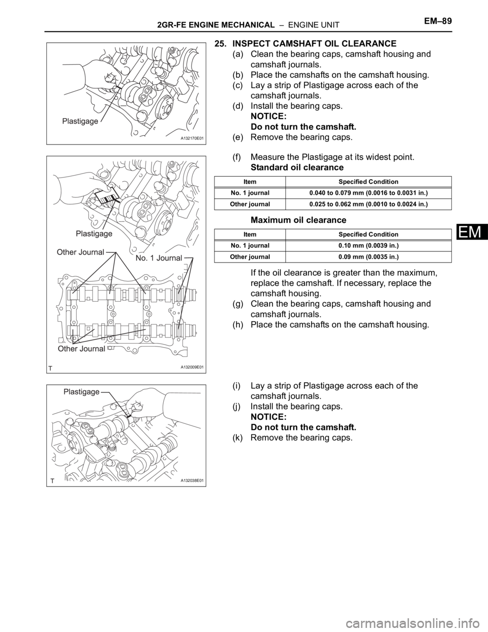
25. INSPECT CAMSHAFT OIL CLEARANCE
(a) Clean the bearing caps, camshaft housing and
camshaft journals.
(b) Place the camshafts on the camshaft housing.
(c) Lay a strip of Plastigage across each of the
camshaft journals.
(d) Install the bearing caps.
NOTICE:
Do not turn the camshaft.
(e) Remove the bearing caps.
(f) Measure the Plastigage at its widest point.
Standard oil clearance
Maximum oil clearance
If the oil clearance is greater than the maximum,
replace the camshaft. If necessary, replace the
camshaft housing.
(g) Clean the bearing caps, camshaft housing and
camshaft journals.
(h) Place the camshafts on the camshaft housing.
(i) Lay a strip of Plastigage across each of the
camshaft journals.
(j) Install the bearing caps.
NOTICE:
Do not turn the camshaft.
(k) Remove the bearing caps.
A132170E01
A132009E01
Item Specified Condition
No. 1 journal 0.040 to 0.079 mm (0.0016 to 0.0031 in.)
Other journal 0.025 to 0.062 mm (0.0010 to 0.0024 in.)
Item Specified Condition
No. 1 journal 0.10 mm (0.0039 in.)
Other journal 0.09 mm (0.0035 in.)
A132038E01
Page 727 of 2000
EM–902GR-FE ENGINE MECHANICAL – ENGINE UNIT
EM
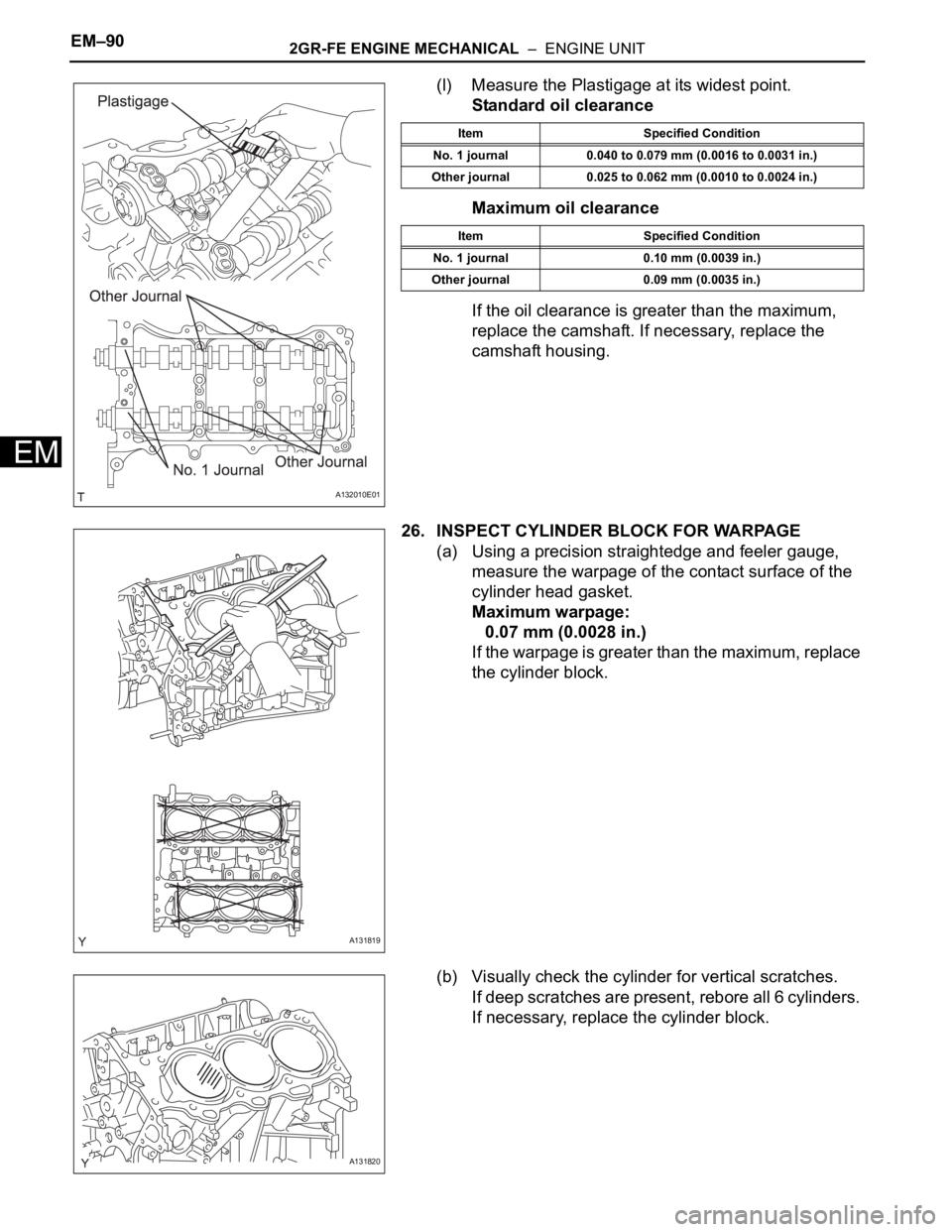
(l) Measure the Plastigage at its widest point.
Standard oil clearance
Maximum oil clearance
If the oil clearance is greater than the maximum,
replace the camshaft. If necessary, replace the
camshaft housing.
26. INSPECT CYLINDER BLOCK FOR WARPAGE
(a) Using a precision straightedge and feeler gauge,
measure the warpage of the contact surface of the
cylinder head gasket.
Maximum warpage:
0.07 mm (0.0028 in.)
If the warpage is greater than the maximum, replace
the cylinder block.
(b) Visually check the cylinder for vertical scratches.
If deep scratches are present, rebore all 6 cylinders.
If necessary, replace the cylinder block.
A132010E01
Item Specified Condition
No. 1 journal 0.040 to 0.079 mm (0.0016 to 0.0031 in.)
Other journal 0.025 to 0.062 mm (0.0010 to 0.0024 in.)
Item Specified Condition
No. 1 journal 0.10 mm (0.0039 in.)
Other journal 0.09 mm (0.0035 in.)
A131819
A131820
Page 728 of 2000
2GR-FE ENGINE MECHANICAL – ENGINE UNITEM–91
EM
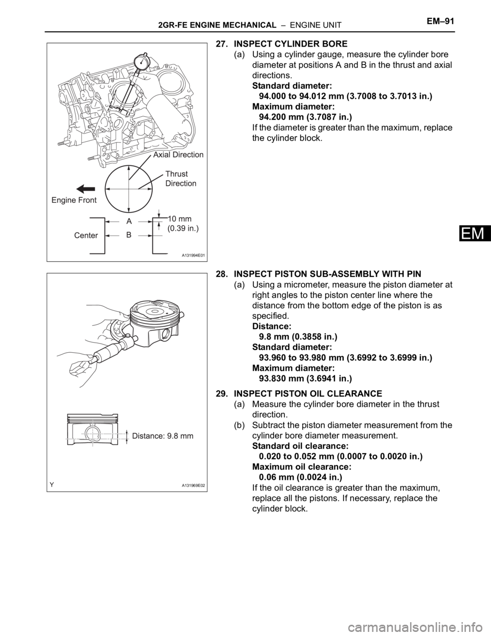
27. INSPECT CYLINDER BORE
(a) Using a cylinder gauge, measure the cylinder bore
diameter at positions A and B in the thrust and axial
directions.
Standard diameter:
94.000 to 94.012 mm (3.7008 to 3.7013 in.)
Maximum diameter:
94.200 mm (3.7087 in.)
If the diameter is greater than the maximum, replace
the cylinder block.
28. INSPECT PISTON SUB-ASSEMBLY WITH PIN
(a) Using a micrometer, measure the piston diameter at
right angles to the piston center line where the
distance from the bottom edge of the piston is as
specified.
Distance:
9.8 mm (0.3858 in.)
Standard diameter:
93.960 to 93.980 mm (3.6992 to 3.6999 in.)
Maximum diameter:
93.830 mm (3.6941 in.)
29. INSPECT PISTON OIL CLEARANCE
(a) Measure the cylinder bore diameter in the thrust
direction.
(b) Subtract the piston diameter measurement from the
cylinder bore diameter measurement.
Standard oil clearance:
0.020 to 0.052 mm (0.0007 to 0.0020 in.)
Maximum oil clearance:
0.06 mm (0.0024 in.)
If the oil clearance is greater than the maximum,
replace all the pistons. If necessary, replace the
cylinder block.
A131994E01
A131969E02
Page 729 of 2000
EM–922GR-FE ENGINE MECHANICAL – ENGINE UNIT
EM
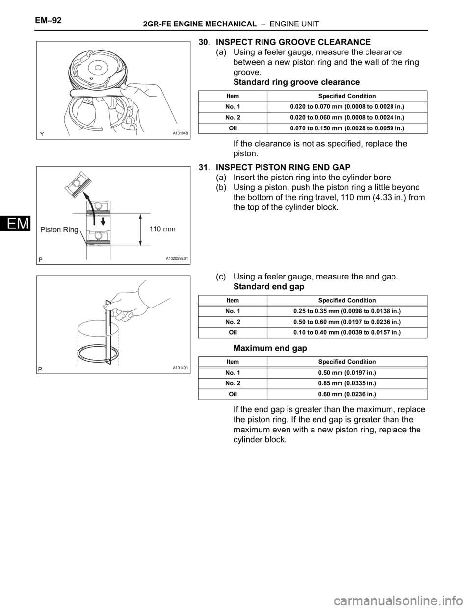
30. INSPECT RING GROOVE CLEARANCE
(a) Using a feeler gauge, measure the clearance
between a new piston ring and the wall of the ring
groove.
Standard ring groove clearance
If the clearance is not as specified, replace the
piston.
31. INSPECT PISTON RING END GAP
(a) Insert the piston ring into the cylinder bore.
(b) Using a piston, push the piston ring a little beyond
the bottom of the ring travel, 110 mm (4.33 in.) from
the top of the cylinder block.
(c) Using a feeler gauge, measure the end gap.
Standard end gap
Maximum end gap
If the end gap is greater than the maximum, replace
the piston ring. If the end gap is greater than the
maximum even with a new piston ring, replace the
cylinder block.
A131948
Item Specified Condition
No. 1 0.020 to 0.070 mm (0.0008 to 0.0028 in.)
No. 2 0.020 to 0.060 mm (0.0008 to 0.0024 in.)
Oil 0.070 to 0.150 mm (0.0028 to 0.0059 in.)
A132059E01
A101491
Item Specified Condition
No. 1 0.25 to 0.35 mm (0.0098 to 0.0138 in.)
No. 2 0.50 to 0.60 mm (0.0197 to 0.0236 in.)
Oil 0.10 to 0.40 mm (0.0039 to 0.0157 in.)
Item Specified Condition
No. 1 0.50 mm (0.0197 in.)
No. 2 0.85 mm (0.0335 in.)
Oil 0.60 mm (0.0236 in.)
Page 730 of 2000
2GR-FE ENGINE MECHANICAL – ENGINE UNITEM–93
EM
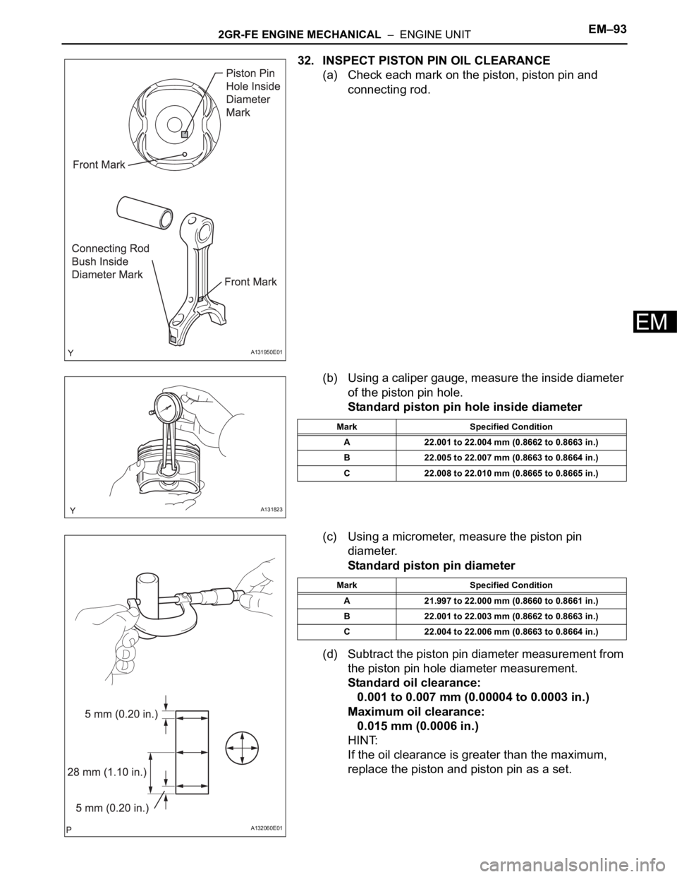
32. INSPECT PISTON PIN OIL CLEARANCE
(a) Check each mark on the piston, piston pin and
connecting rod.
(b) Using a caliper gauge, measure the inside diameter
of the piston pin hole.
Standard piston pin hole inside diameter
(c) Using a micrometer, measure the piston pin
diameter.
Standard piston pin diameter
(d) Subtract the piston pin diameter measurement from
the piston pin hole diameter measurement.
Standard oil clearance:
0.001 to 0.007 mm (0.00004 to 0.0003 in.)
Maximum oil clearance:
0.015 mm (0.0006 in.)
HINT:
If the oil clearance is greater than the maximum,
replace the piston and piston pin as a set.
A131950E01
A131823
Mark Specified Condition
A 22.001 to 22.004 mm (0.8662 to 0.8663 in.)
B 22.005 to 22.007 mm (0.8663 to 0.8664 in.)
C 22.008 to 22.010 mm (0.8665 to 0.8665 in.)
A132060E01
Mark Specified Condition
A 21.997 to 22.000 mm (0.8660 to 0.8661 in.)
B 22.001 to 22.003 mm (0.8662 to 0.8663 in.)
C 22.004 to 22.006 mm (0.8663 to 0.8664 in.)