TOYOTA RAV4 2006 Service Repair Manual
Manufacturer: TOYOTA, Model Year: 2006, Model line: RAV4, Model: TOYOTA RAV4 2006Pages: 2000, PDF Size: 45.84 MB
Page 731 of 2000
EM–942GR-FE ENGINE MECHANICAL – ENGINE UNIT
EM
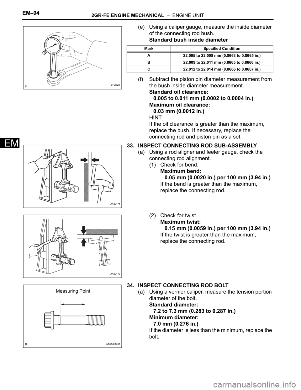
(e) Using a caliper gauge, measure the inside diameter
of the connecting rod bush.
Standard bush inside diameter
(f) Subtract the piston pin diameter measurement from
the bush inside diameter measurement.
Standard oil clearance:
0.005 to 0.011 mm (0.0002 to 0.0004 in.)
Maximum oil clearance:
0.03 mm (0.0012 in.)
HINT:
If the oil clearance is greater than the maximum,
replace the bush. If necessary, replace the
connecting rod and piston pin as a set.
33. INSPECT CONNECTING ROD SUB-ASSEMBLY
(a) Using a rod aligner and feeler gauge, check the
connecting rod alignment.
(1) Check for bend.
Maximum bend:
0.05 mm (0.0020 in.) per 100 mm (3.94 in.)
If the bend is greater than the maximum,
replace the connecting rod.
(2) Check for twist.
Maximum twist:
0.15 mm (0.0059 in.) per 100 mm (3.94 in.)
If the twist is greater than the maximum,
replace the connecting rod.
34. INSPECT CONNECTING ROD BOLT
(a) Using a vernier caliper, measure the tension portion
diameter of the bolt.
Standard diameter:
7.2 to 7.3 mm (0.283 to 0.287 in.)
Minimum diameter:
7.0 mm (0.276 in.)
If the diameter is less than the minimum, replace the
bolt.
A132061
Mark Specified Condition
A 22.005 to 22.008 mm (0.8663 to 0.8665 in.)
B 22.009 to 22.011 mm (0.8665 to 0.8666 in.)
C 22.012 to 22.014 mm (0.8666 to 0.8667 in.)
A132171
A132172
A132062E01
Page 732 of 2000
2GR-FE ENGINE MECHANICAL – ENGINE UNITEM–95
EM
35. INSPECT CRANKSHAFT
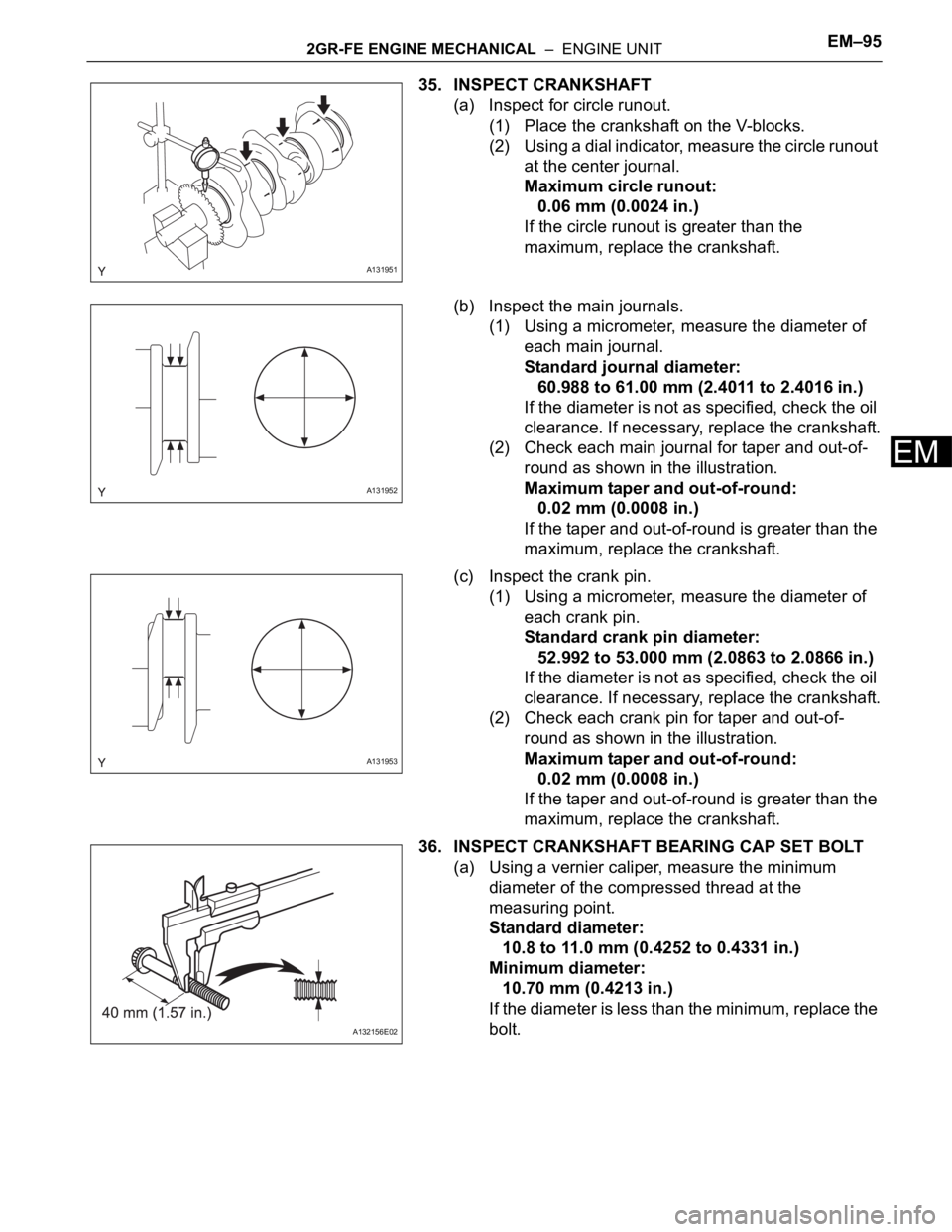
(a) Inspect for circle runout.
(1) Place the crankshaft on the V-blocks.
(2) Using a dial indicator, measure the circle runout
at the center journal.
Maximum circle runout:
0.06 mm (0.0024 in.)
If the circle runout is greater than the
maximum, replace the crankshaft.
(b) Inspect the main journals.
(1) Using a micrometer, measure the diameter of
each main journal.
Standard journal diameter:
60.988 to 61.00 mm (2.4011 to 2.4016 in.)
If the diameter is not as specified, check the oil
clearance. If necessary, replace the crankshaft.
(2) Check each main journal for taper and out-of-
round as shown in the illustration.
Maximum taper and out-of-round:
0.02 mm (0.0008 in.)
If the taper and out-of-round is greater than the
maximum, replace the crankshaft.
(c) Inspect the crank pin.
(1) Using a micrometer, measure the diameter of
each crank pin.
Standard crank pin diameter:
52.992 to 53.000 mm (2.0863 to 2.0866 in.)
If the diameter is not as specified, check the oil
clearance. If necessary, replace the crankshaft.
(2) Check each crank pin for taper and out-of-
round as shown in the illustration.
Maximum taper and out-of-round:
0.02 mm (0.0008 in.)
If the taper and out-of-round is greater than the
maximum, replace the crankshaft.
36. INSPECT CRANKSHAFT BEARING CAP SET BOLT
(a) Using a vernier caliper, measure the minimum
diameter of the compressed thread at the
measuring point.
Standard diameter:
10.8 to 11.0 mm (0.4252 to 0.4331 in.)
Minimum diameter:
10.70 mm (0.4213 in.)
If the diameter is less than the minimum, replace the
bolt.
A131951
A131952
A131953
A132156E02
Page 733 of 2000
EM–962GR-FE ENGINE MECHANICAL – ENGINE UNIT
EM
REPLACEMENT
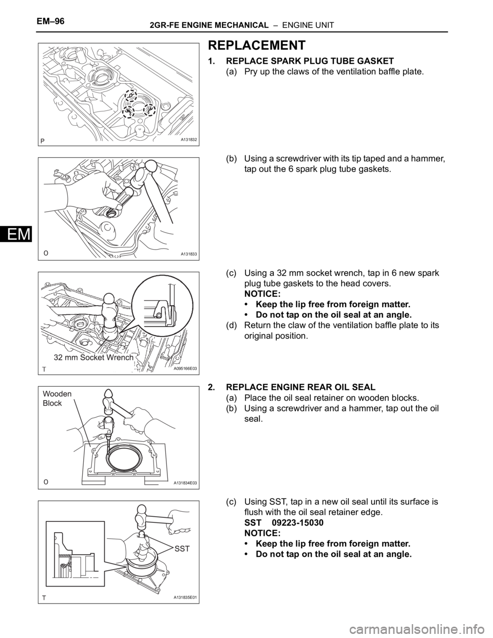
1. REPLACE SPARK PLUG TUBE GASKET
(a) Pry up the claws of the ventilation baffle plate.
(b) Using a screwdriver with its tip taped and a hammer,
tap out the 6 spark plug tube gaskets.
(c) Using a 32 mm socket wrench, tap in 6 new spark
plug tube gaskets to the head covers.
NOTICE:
• Keep the lip free from foreign matter.
• Do not tap on the oil seal at an angle.
(d) Return the claw of the ventilation baffle plate to its
original position.
2. REPLACE ENGINE REAR OIL SEAL
(a) Place the oil seal retainer on wooden blocks.
(b) Using a screwdriver and a hammer, tap out the oil
seal.
(c) Using SST, tap in a new oil seal until its surface is
flush with the oil seal retainer edge.
SST 09223-15030
NOTICE:
• Keep the lip free from foreign matter.
• Do not tap on the oil seal at an angle.
A131832
A131833
A095166E03
A131834E03
A131835E01
Page 734 of 2000
2GR-FE ENGINE MECHANICAL – ENGINE UNITEM–97
EM
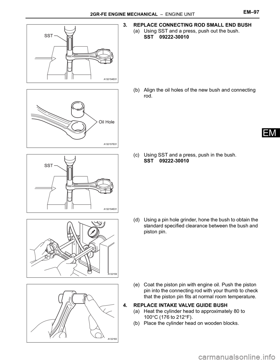
3. REPLACE CONNECTING ROD SMALL END BUSH
(a) Using SST and a press, push out the bush.
SST 09222-30010
(b) Align the oil holes of the new bush and connecting
rod.
(c) Using SST and a press, push in the bush.
SST 09222-30010
(d) Using a pin hole grinder, hone the bush to obtain the
standard specified clearance between the bush and
piston pin.
(e) Coat the piston pin with engine oil. Push the piston
pin into the connecting rod with your thumb to check
that the piston pin fits at normal room temperature.
4. REPLACE INTAKE VALVE GUIDE BUSH
(a) Heat the cylinder head to approximately 80 to
100
C (176 to 212F).
(b) Place the cylinder head on wooden blocks.
A132154E01
A132157E01
A132154E01
A132159
A132160
Page 735 of 2000
EM–982GR-FE ENGINE MECHANICAL – ENGINE UNIT
EM
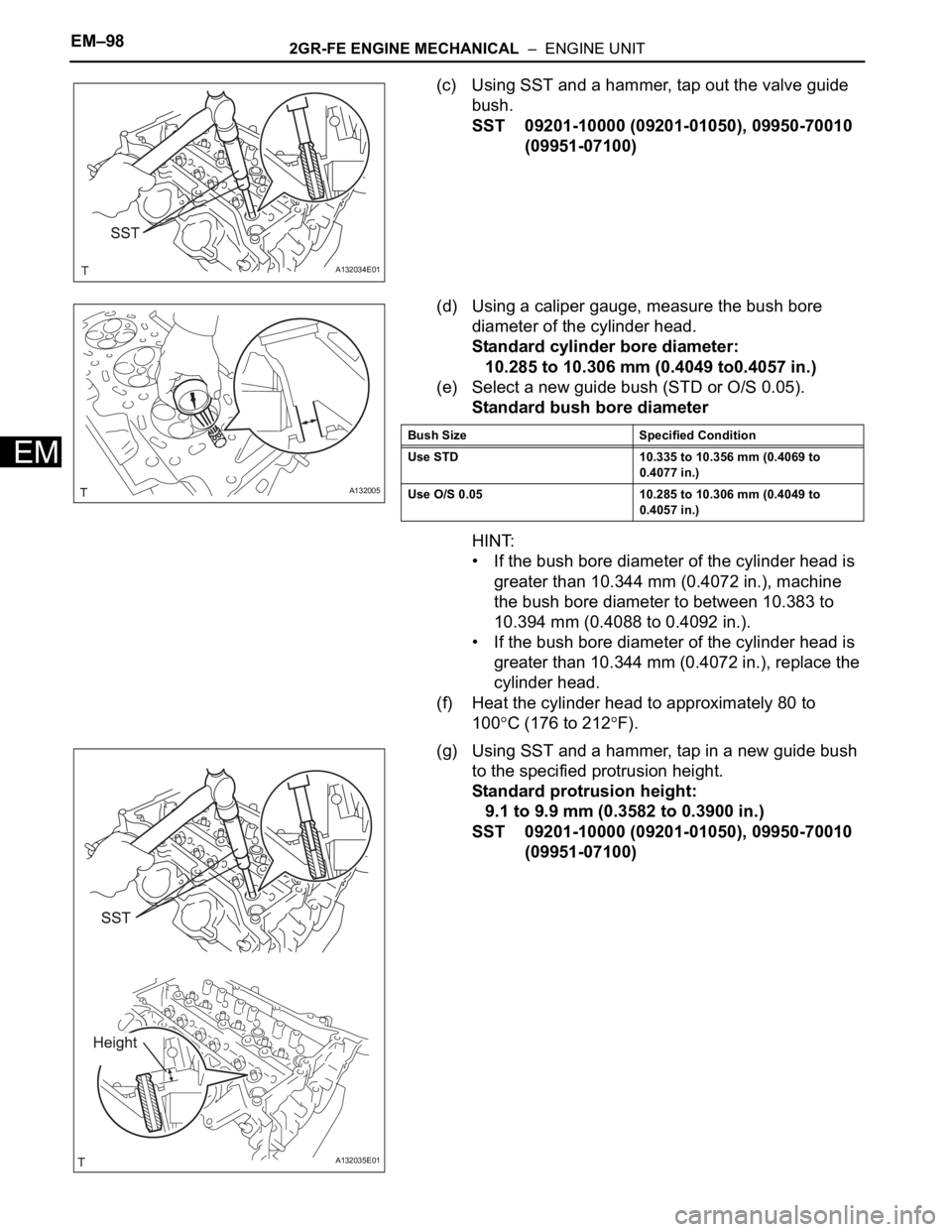
(c) Using SST and a hammer, tap out the valve guide
bush.
SST 09201-10000 (09201-01050), 09950-70010
(09951-07100)
(d) Using a caliper gauge, measure the bush bore
diameter of the cylinder head.
Standard cylinder bore diameter:
10.285 to 10.306 mm (0.4049 to0.4057 in.)
(e) Select a new guide bush (STD or O/S 0.05).
Standard bush bore diameter
HINT:
• If the bush bore diameter of the cylinder head is
greater than 10.344 mm (0.4072 in.), machine
the bush bore diameter to between 10.383 to
10.394 mm (0.4088 to 0.4092 in.).
• If the bush bore diameter of the cylinder head is
greater than 10.344 mm (0.4072 in.), replace the
cylinder head.
(f) Heat the cylinder head to approximately 80 to
100
C (176 to 212F).
(g) Using SST and a hammer, tap in a new guide bush
to the specified protrusion height.
Standard protrusion height:
9.1 to 9.9 mm (0.3582 to 0.3900 in.)
SST 09201-10000 (09201-01050), 09950-70010
(09951-07100)
A132034E01
A132005
Bush Size Specified Condition
Use STD 10.335 to 10.356 mm (0.4069 to
0.4077 in.)
Use O/S 0.05 10.285 to 10.306 mm (0.4049 to
0.4057 in.)
A132035E01
Page 736 of 2000
2GR-FE ENGINE MECHANICAL – ENGINE UNITEM–99
EM
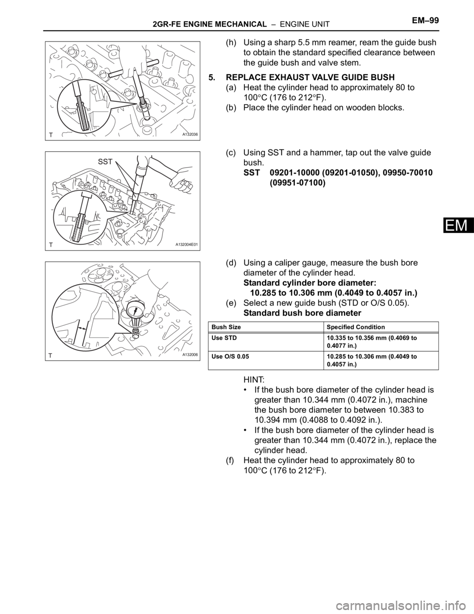
(h) Using a sharp 5.5 mm reamer, ream the guide bush
to obtain the standard specified clearance between
the guide bush and valve stem.
5. REPLACE EXHAUST VALVE GUIDE BUSH
(a) Heat the cylinder head to approximately 80 to
100
C (176 to 212F).
(b) Place the cylinder head on wooden blocks.
(c) Using SST and a hammer, tap out the valve guide
bush.
SST 09201-10000 (09201-01050), 09950-70010
(09951-07100)
(d) Using a caliper gauge, measure the bush bore
diameter of the cylinder head.
Standard cylinder bore diameter:
10.285 to 10.306 mm (0.4049 to 0.4057 in.)
(e) Select a new guide bush (STD or O/S 0.05).
Standard bush bore diameter
HINT:
• If the bush bore diameter of the cylinder head is
greater than 10.344 mm (0.4072 in.), machine
the bush bore diameter to between 10.383 to
10.394 mm (0.4088 to 0.4092 in.).
• If the bush bore diameter of the cylinder head is
greater than 10.344 mm (0.4072 in.), replace the
cylinder head.
(f) Heat the cylinder head to approximately 80 to
100
C (176 to 212F).
A132036
A132004E01
A132006
Bush Size Specified Condition
Use STD 10.335 to 10.356 mm (0.4069 to
0.4077 in.)
Use O/S 0.05 10.285 to 10.306 mm (0.4049 to
0.4057 in.)
Page 737 of 2000
EM–1002GR-FE ENGINE MECHANICAL – ENGINE UNIT
EM
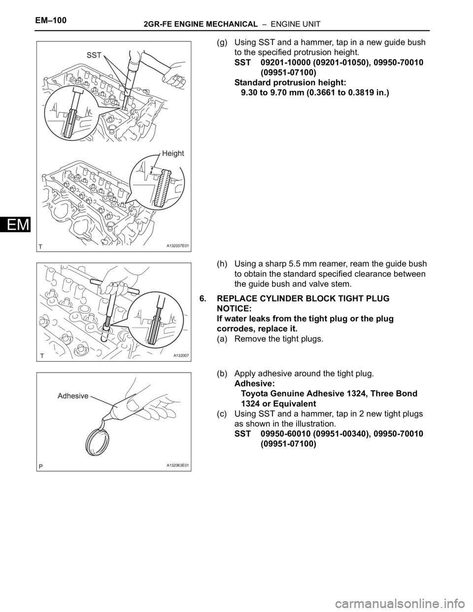
(g) Using SST and a hammer, tap in a new guide bush
to the specified protrusion height.
SST 09201-10000 (09201-01050), 09950-70010
(09951-07100)
Standard protrusion height:
9.30 to 9.70 mm (0.3661 to 0.3819 in.)
(h) Using a sharp 5.5 mm reamer, ream the guide bush
to obtain the standard specified clearance between
the guide bush and valve stem.
6. REPLACE CYLINDER BLOCK TIGHT PLUG
NOTICE:
If water leaks from the tight plug or the plug
corrodes, replace it.
(a) Remove the tight plugs.
(b) Apply adhesive around the tight plug.
Adhesive:
Toyota Genuine Adhesive 1324, Three Bond
1324 or Equivalent
(c) Using SST and a hammer, tap in 2 new tight plugs
as shown in the illustration.
SST 09950-60010 (09951-00340), 09950-70010
(09951-07100)
A132037E01
A132007
A132063E01
Page 738 of 2000
2GR-FE ENGINE MECHANICAL – ENGINE UNITEM–101
EM
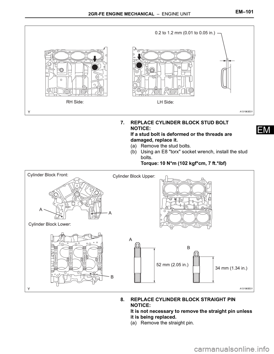
7. REPLACE CYLINDER BLOCK STUD BOLT
NOTICE:
If a stud bolt is deformed or the threads are
damaged, replace it.
(a) Remove the stud bolts.
(b) Using an E8 "torx" socket wrench, install the stud
bolts.
Torque: 10 N*m (102 kgf*cm, 7 ft.*lbf)
8. REPLACE CYLINDER BLOCK STRAIGHT PIN
NOTICE:
It is not necessary to remove the straight pin unless
it is being replaced.
(a) Remove the straight pin.
A131963E01
A131965E01
Page 739 of 2000
EM–1022GR-FE ENGINE MECHANICAL – ENGINE UNIT
EM
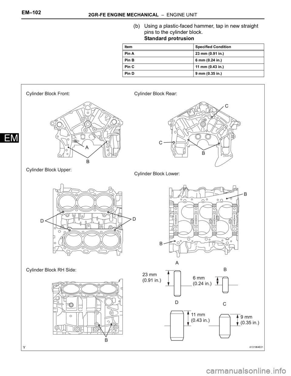
(b) Using a plastic-faced hammer, tap in new straight
pins to the cylinder block.
Standard protrusion
Item Specified Condition
Pin A 23 mm (0.91 in.)
Pin B 6 mm (0.24 in.)
Pin C 11 mm (0.43 in.)
Pin D 9 mm (0.35 in.)
A131964E01
Page 740 of 2000
2GR-FE ENGINE MECHANICAL – ENGINE UNITEM–103
EM
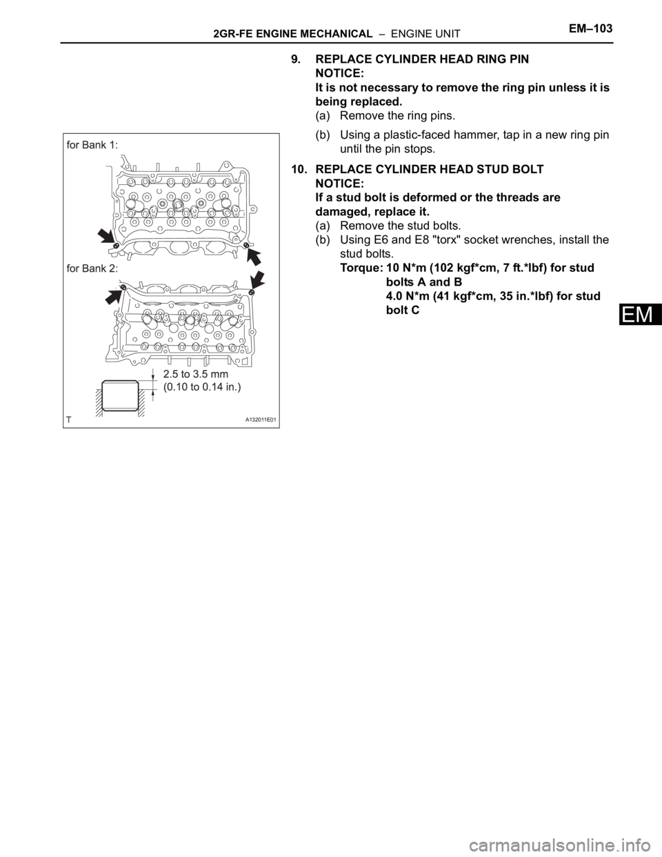
9. REPLACE CYLINDER HEAD RING PIN
NOTICE:
It is not necessary to remove the ring pin unless it is
being replaced.
(a) Remove the ring pins.
(b) Using a plastic-faced hammer, tap in a new ring pin
until the pin stops.
10. REPLACE CYLINDER HEAD STUD BOLT
NOTICE:
If a stud bolt is deformed or the threads are
damaged, replace it.
(a) Remove the stud bolts.
(b) Using E6 and E8 "torx" socket wrenches, install the
stud bolts.
Torque: 10 N*m (102 kgf*cm, 7 ft.*lbf) for stud
bolts A and B
4.0 N*m (41 kgf*cm, 35 in.*lbf) for stud
bolt C
A132011E01