clock TOYOTA RAV4 PLUG-IN HYBRID 2023 User Guide
[x] Cancel search | Manufacturer: TOYOTA, Model Year: 2023, Model line: RAV4 PLUG-IN HYBRID, Model: TOYOTA RAV4 PLUG-IN HYBRID 2023Pages: 718, PDF Size: 167.55 MB
Page 211 of 718
209
3
3-1. Instrument cluster
Vehicle status information and indicators
• “Drive Info Type”
Select to change the drive information
type display between trip and total.
( P.204).
• “Drive Info Items”
Select to set the items on the upper and
lower side of the drive information
screen from three items, average
speed, distance and total time.
“Closing Display”
Select to set the items displayed when
the power switch is turned off.
“Pop-Up Display” (if equipped)
Select to enable/disable the following
pop-up displays, which may appear in
some situations.
• Intersection guidance display of the
navigation system-linked system (if
equipped)
• Incoming call display of the hands-
free phone system (if equipped)
• Audio operation
• Volume operation
• Voice control (if equipped)
“Calender”
Select to set up the calender.
This can only be set if GPS calibration
of clock is turned off in the multimedia
system settings.
“MID OFF”
A blank screen is displayed
“Default Settings”
Select to reset the meter display set-
tings.
■Suspension of the settings display
●In the following situations, operation of the settings display will be temporarily suspended.
• When a warning message appears on
the multi-information display
• When the vehicle begins to move
●Settings for functions not equipped to
the vehicle are not displayed.
●When a function is turned off, the
related settings for that function are not selectable.
Select to display warning mes-
sages and measures to be taken if
a malfunction is detected.
( P.544)
Displays suggestions to the driver
in the following situations. To select
a response to a displayed sugges-
tion, use the meter control
switches.
WARNING
■Cautions during setting up the
display
As the hybrid system needs to be operating during setting up the dis-
play, ensure that the vehicle is parked in a place with adequate ventilation. In a closed area such as a garage,
exhaust gases including harmful car- bon monoxide (CO) may collect and enter the vehicle. This may lead to
death or a serious health hazard.
NOTICE
■During setting up the display
To prevent 12-volt battery discharge, ensure that the hybrid system is oper-
ating while setting up the display fea- tures.
Warning message display
Convenience Services (Sug-
gestion function)
Page 222 of 718
2203-1. Instrument cluster
■ Settings
“Language”
Select to change the language
on the multi-information display.
“Units”
Select to change the unit of mea-
sure for fuel consumption.
Meter Type
Select to change the meter type
setting.
Meter Style
Select to change the meter style.
Dial Type
Select to change dial type.
( P.193)
Depending on the selected dial type,
this item will not be displayed.
EV indicator
Select to enable/disable the EV
indicator.
Fuel Economy
Select to change the display on
Fuel Economy. ( P.213)
“Hybrid System”
Select to enable/disable refer-
ence operation range.
“Power Consumption”
Select to change the display on
Power Consumption. ( P.213)
Drive Info
Select to change displayed items
on drive information display.
( P.216)
Pop-Up Display
Select to enable/disable the pop-
up displays, which may appear in
some situations.
“Calender”
Select to set up the calender.
This can only be set if GPS cali-
bration of clock is turned off in
the multimedia system settings.
Default Settings
Select to reset the meter display
settings.
■Suspension of the settings display
●In the following situations, operation of the settings display will be temporarily
suspended. • When a warning message appears on the multi-information display
• When the vehicle begins to move
●Settings for functions not equipped to
the vehicle are not displayed.
●When a function is turned off, the
related settings for that function are not selectable.
WARNING
■Cautions during setting up the
display
As the hybrid system needs to be operating during setting up the dis-
play, ensure that the vehicle is parked in a place with adequate ventilation. In a closed area such as a garage,
exhaust gases including harmful car- bon monoxide (CO) may collect and enter the vehicle. This may lead to
death or a serious health hazard.
NOTICE
■During setting up the display
To prevent 12-volt battery discharge, ensure that the hybrid system is oper-
ating while setting up the display fea- tures.
Page 309 of 718
307
5
5-1. Before driving
Driving
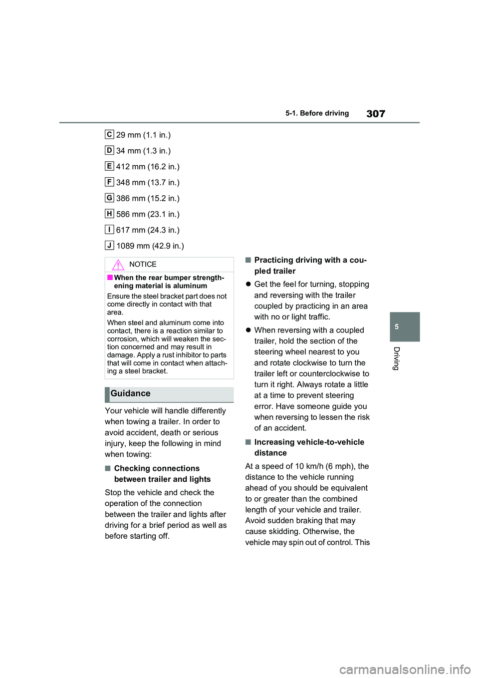
29 mm (1.1 in.)
34 mm (1.3 in.)
412 mm (16.2 in.)
348 mm (13.7 in.)
386 mm (15.2 in.)
586 mm (23.1 in.)
617 mm (24.3 in.)
1089 mm (42.9 in.)
Your vehicle will handle differently
when towing a trailer. In order to
avoid accident, death or serious
injury, keep the following in mind
when towing:
■Checking connections
between trailer and lights
Stop the vehicle and check the
operation of the connection
between the trailer and lights after
driving for a brief period as well as
before starting off.
■Practicing driving with a cou-
pled trailer
Get the feel for turning, stopping
and reversing with the trailer
coupled by practicing in an area
with no or light traffic.
When reversing with a coupled
trailer, hold the section of the
steering wheel nearest to you
and rotate clockwise to turn the
trailer left or counterclockwise to
turn it right. Always rotate a little
at a time to prevent steering
error. Have someone guide you
when reversing to lessen the risk
of an accident.
■Increasing vehicle-to-vehicle
distance
At a speed of 10 km/h (6 mph), the
distance to the vehicle running
ahead of you should be equivalent
to or greater than the combined
length of your vehicle and trailer.
Avoid sudden braking that may
cause skidding. Otherwise, the
vehicle may spin out of control. This
C
D
E
F
G
H
I
J
NOTICE
■When the rear bumper strength-
ening material is aluminum
Ensure the steel bracket part does not come directly in contact with that
area.
When steel and aluminum come into contact, there is a reaction similar to
corrosion, which will weaken the sec- tion concerned and may result in damage. Apply a rust inhibitor to parts
that will come in contact when attach- ing a steel bracket.
Guidance
Page 433 of 718
431
6
6-1. Using the air conditioning system and defogger
Interior features
■Adjusting the temperature set-
ting
Turn driver’s side temperature con-
trol dial clockwise to increases the
temperature and turn the dial coun-
terclockwise to decreases the tem-
perature.
The air conditioning system switches
between individual and simultaneous
modes each time the “DUAL” switch is
pressed.
Simultaneous mode (the indicator on
the “DUAL” switch is off):
The driver’s side temperature control
dial can be used to adjust the tempera-
ture for the driver’s and passenger’s
side. At this time, operate the passen-
ger’s side temperature control dial to
enter individual mode.
Individual mode (the indicator on the
“DUAL” switch is on):
The temperature for the driver’s and
passenger’s side can be adjusted sepa-
rately.
■Setting the fan speed
Press the fan speed increase
switch to increase the fan speed
and the fan speed decrease switch
to decrease the fan speed.
Pressing the “OFF” switch to turns off
the fan.
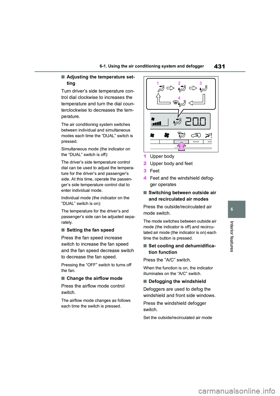
■Change the airflow mode
Press the airflow mode control
switch.
The airflow mode changes as follows
each time the switch is pressed.
1 Upper body
2 Upper body and feet
3 Feet
4 Feet and the windshield defog-
ger operates
■Switching between outside air
and recirculated air modes
Press the outside/recirculated air
mode switch.
The mode switches between outside air
mode (the indicator is off) and recircu-
lated air mode (the indicator is on) each
time the button is pressed.
■Set cooling and dehumidifica-
tion function
Press the “A/C” switch.
When the function is on, the indicator
illuminates on the “A/C” switch.
■Defogging the windshield
Defoggers are used to defog the
windshield and front side windows.
Press the windshield defogger
switch.
Set the outside/recirculated air mode
112233
44
Page 482 of 718
4807-3. Do-it-yourself maintenance
oil level on the dipstick.
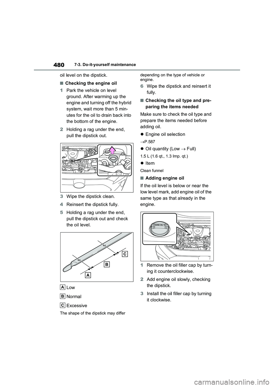
■Checking the engine oil
1Park the vehicle on level
ground. After warming up the
engine and turning off the hybrid
system, wait more than 5 min-
utes for the oil to drain back into
the bottom of the engine.
2Holding a rag under the end,
pull the dipstick out.
3Wipe the dipstick clean.
4Reinsert the dipstick fully.
5Holding a rag under the end,
pull the dipstick out and check
the oil level.
Low
Normal
Excessive
The shape of the dipstick may differ depending on the type of vehicle or
engine.
6Wipe the dipstick and reinsert it
fully.
■Checking the oil type and pre-
paring the items needed
Make sure to check the oil type and
prepare the items needed before
adding oil.
Engine oil selection
P.587
Oil quantity (Low Full)
1.5 L (1.6 qt., 1.3 Imp. qt.)
Item
Clean funnel
■Adding engine oil
If the oil level is below or near the
low level mark, add engine oil of the
same type as that already in the
engine.
1Remove the oil filler cap by turn-
ing it counterclockwise.
2Add engine oil slowly, checking
the dipstick.
3Install the oil filler cap by turning
it clockwise.
A
B
C
Page 520 of 718
5187-3. Do-it-yourself maintenance
vehicle.
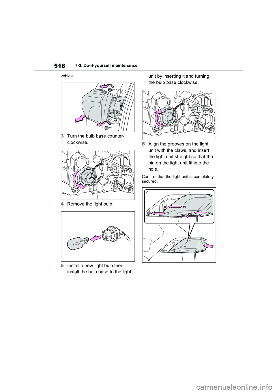
3Turn the bulb base counter-
clockwise.
4Remove the light bulb.
5Install a new light bulb then
install the bulb base to the light unit by inserting it and turning
the bulb base clockwise.
6Align the grooves on the light
unit with the claws, and insert
the light unit straight so that the
pin on the light unit fit into the
hole.
Confirm that the light unit is completely
secured.
Page 521 of 718
519
7 7-3. Do-it-yourself maintenance
Maintenance and care
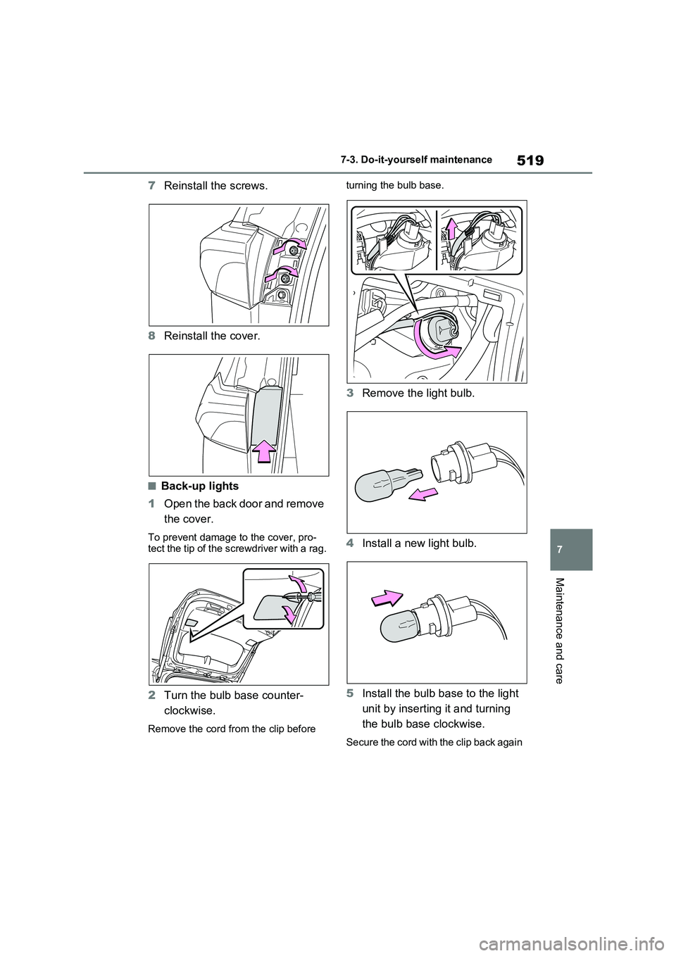
7Reinstall the screws.
8Reinstall the cover.
■Back-up lights
1Open the back door and remove
the cover.
To prevent damage to the cover, pro-
tect the tip of the screwdriver with a rag.
2Turn the bulb base counter-
clockwise.
Remove the cord from the clip before turning the bulb base.
3Remove the light bulb.
4Install a new light bulb.
5Install the bulb base to the light
unit by inserting it and turning
the bulb base clockwise.
Secure the cord with the clip back again
Page 523 of 718
521
7 7-3. Do-it-yourself maintenance
Maintenance and care
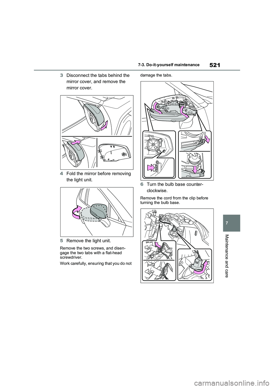
3Disconnect the tabs behind the
mirror cover, and remove the
mirror cover.
4Fold the mirror before removing
the light unit.
5Remove the light unit.
Remove the two screws, and disen-
gage the two tabs with a flat-head
screwdriver.
Work carefully, ensuring that you do not damage the tabs.
6Turn the bulb base counter-
clockwise.
Remove the cord from the clip before
turning the bulb base.
Page 524 of 718

5227-3. Do-it-yourself maintenance
7Remove the light bulb.
8Install a new light bulb then
install the bulb base to the light
unit by inserting it and turning
the bulb base clockwise.
Secure the cord with the clip back again
after installing the bulb base.
9Install the light unit.
Make sure that the two tabs of the light
unit are engaged securely, and install the two screws.
10Extend the mirror.
11Install the mirror cover.
Page 555 of 718
553
8
8-2. Steps to take in an emergency
When trouble arises
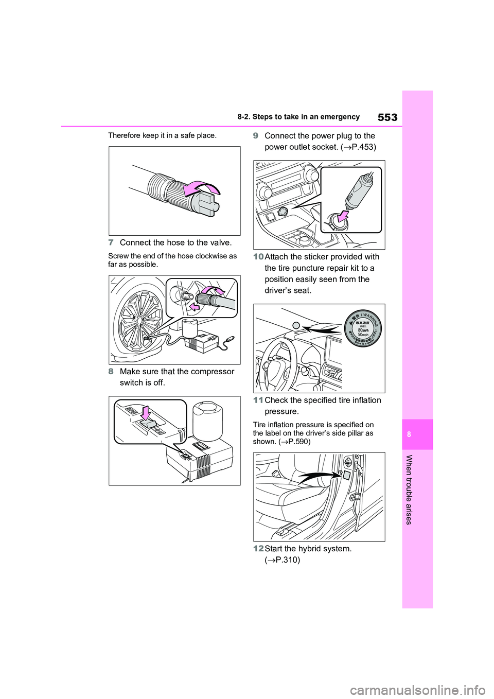
Therefore keep it in a safe place.
7 Connect the hose to the valve.
Screw the end of the hose clockwise as
far as possible.
8 Make sure that the compressor
switch is off.
9 Connect the power plug to the
power outlet socket. ( P.453)
10 Attach the sticker provided with
the tire puncture repair kit to a
position easily seen from the
driver’s seat.
11 Check the specified tire inflation
pressure.
Tire inflation pressure is specified on the label on the driver’s side pillar as
shown. ( P.590)
12Start the hybrid system.
( P.310)