mirror TOYOTA RAV4 PLUG-IN HYBRID 2023 Owner's Guide
[x] Cancel search | Manufacturer: TOYOTA, Model Year: 2023, Model line: RAV4 PLUG-IN HYBRID, Model: TOYOTA RAV4 PLUG-IN HYBRID 2023Pages: 718, PDF Size: 167.55 MB
Page 342 of 718
3405-5. Using the driving support systems
WARNING
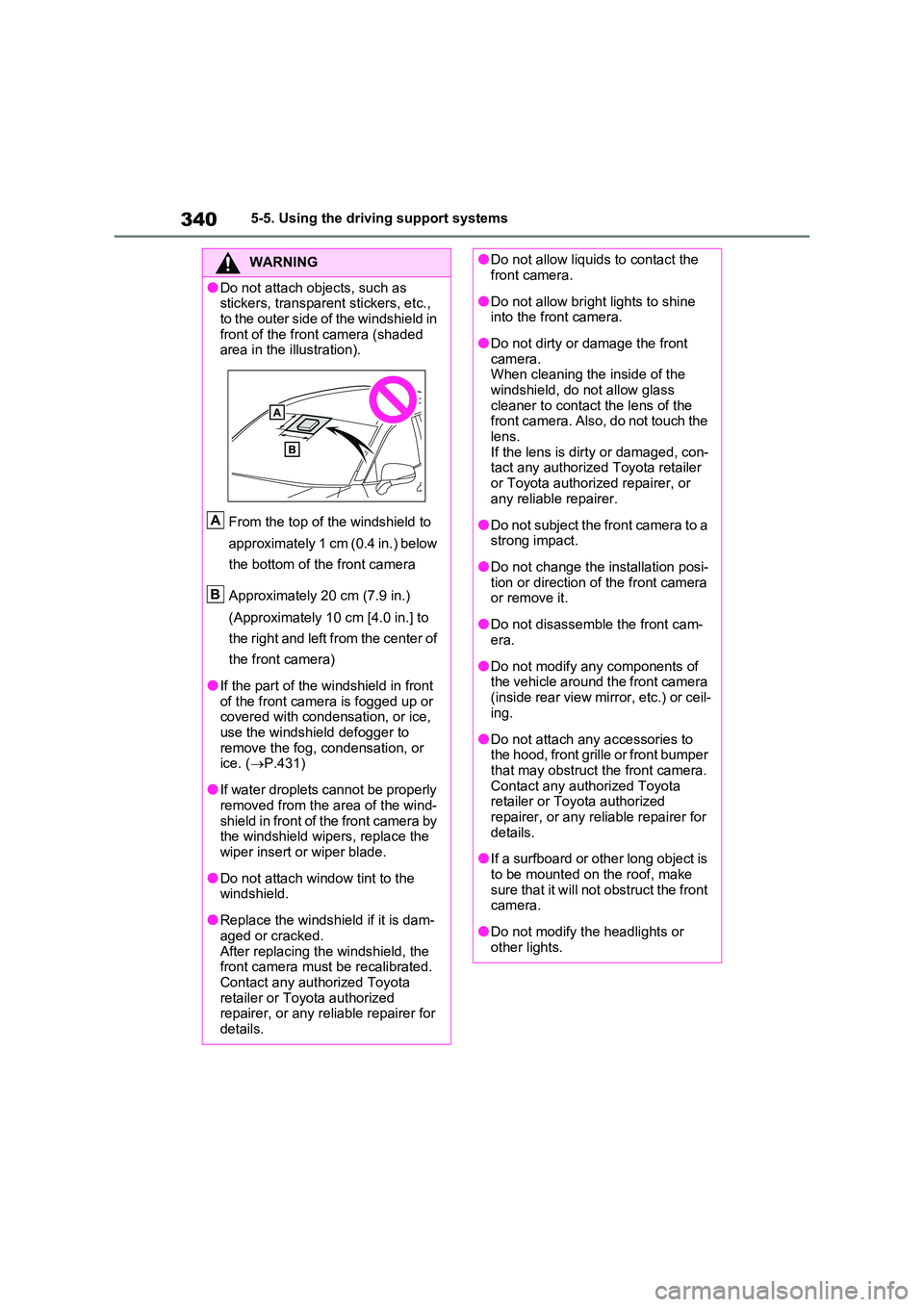
●Do not attach objects, such as stickers, transparent stickers, etc.,
to the outer side of the windshield in front of the front camera (shaded area in the illustration).
From the top of the windshield to
approximately 1 cm (0.4 in.) below
the bottom of the front camera
Approximately 20 cm (7.9 in.)
(Approximately 10 cm [4.0 in.] to
the right and left from the center of
the front camera)
●If the part of the windshield in front of the front camera is fogged up or covered with condensation, or ice,
use the windshield defogger to remove the fog, condensation, or ice. ( P.431)
●If water droplets cannot be properly removed from the area of the wind-
shield in front of the front camera by the windshield wipers, replace the wiper insert or wiper blade.
●Do not attach window tint to the windshield.
●Replace the windshield if it is dam-aged or cracked.
After replacing the windshield, the front camera must be recalibrated. Contact any authorized Toyota
retailer or Toyota authorized repairer, or any reliable repairer for details.
A
B
●Do not allow liquids to contact the front camera.
●Do not allow bright lights to shine into the front camera.
●Do not dirty or damage the front camera. When cleaning the inside of the
windshield, do not allow glass cleaner to contact the lens of the front camera. Also, do not touch the
lens. If the lens is dirty or damaged, con-tact any authorized Toyota retailer
or Toyota authorized repairer, or any reliable repairer.
●Do not subject the front camera to a strong impact.
●Do not change the installation posi-tion or direction of the front camera or remove it.
●Do not disassemble the front cam-era.
●Do not modify any components of the vehicle around the front camera
(inside rear view mirror, etc.) or ceil- ing.
●Do not attach any accessories to the hood, front grille or front bumper that may obstruct the front camera.
Contact any authorized Toyota retailer or Toyota authorized repairer, or any reliable repairer for
details.
●If a surfboard or other long object is
to be mounted on the roof, make sure that it will not obstruct the front camera.
●Do not modify the headlights or other lights.
Page 388 of 718
3865-5. Using the driving support systems
■Automatic speed limiter cancella-
tion
The set speed is automatically canceled when the cruise control is activated.
■If the speed limiter indicator turns
off and “Speed Limiter Malfunction Visit Your Dealer” is displayed
Stop the hybrid system and then restart
the hybrid system. After restarting the hybrid system, set the speed limiter.If the speed limiter cannot be set, there
may be a malfunction in the speed lim- iter system. Have the vehicle inspected by any authorized Toyota retailer or
Toyota authorized repairer, or any reli- able repairer.
*: If equipped
BSM (Blind Spot Moni-
tor)*
The Blind Spot Monitor is a
system that has 2 functions:
The BSM (Blind Spot Monitor)
function
Assists the driver in making a
decision when changing lanes
The RCTA (Rear Crossing
Traffic Alert) function
Assists the driver when backing
up
These functions use the same
sensors.
WARNING
■Cautions regarding the use of the BSM function
The driver is solely responsible for safe driving. Always drive safely, tak-ing care to observe your surround-
ings. The BSM function is a supplementary function which alerts the driver that a
vehicle is in a blind spot of the outside rear view mirrors or is approaching rapidly from behind into a blind spot.
Do not overly rely on the BSM func- tion. As the function cannot judge if it is safe to change lanes, over reliance
could lead to an accident resulting in death or serious injury.
As the system may not function cor-
rectly under certain conditions, the driver’s own visual confirmation of safety is necessary.
Page 389 of 718
387
5
5-5. Using the driving support systems
Driving
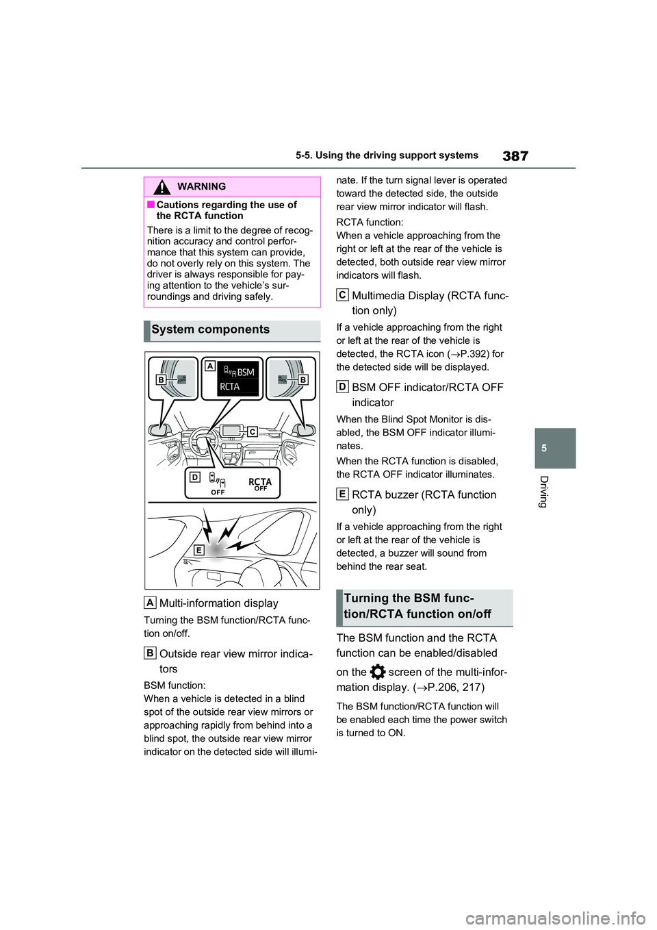
Multi-information display
Turning the BSM function/RCTA func-
tion on/off.
Outside rear view mirror indica-
tors
BSM function:
When a vehicle is detected in a blind
spot of the outside rear view mirrors or
approaching rapidly from behind into a
blind spot, the outside rear view mirror
indicator on the detected side will illumi-
nate. If the turn signal lever is operated
toward the detected side, the outside
rear view mirror indicator will flash.
RCTA function:
When a vehicle approaching from the
right or left at the rear of the vehicle is
detected, both outside rear view mirror
indicators will flash.
Multimedia Display (RCTA func-
tion only)
If a vehicle approaching from the right
or left at the rear of the vehicle is
detected, the RCTA icon ( P.392) for
the detected side will be displayed.
BSM OFF indicator/RCTA OFF
indicator
When the Blind Spot Monitor is dis-
abled, the BSM OFF indicator illumi-
nates.
When the RCTA function is disabled,
the RCTA OFF indicator illuminates.
RCTA buzzer (RCTA function
only)
If a vehicle approaching from the right
or left at the rear of the vehicle is
detected, a buzzer will sound from
behind the rear seat.
The BSM function and the RCTA
function can be enabled/disabled
on the screen of the multi-infor-
mation display. ( P.206, 217)
The BSM function/RCTA function will
be enabled each time the power switch
is turned to ON.
WARNING
■Cautions regarding the use of the RCTA function
There is a limit to the degree of recog- nition accuracy and control perfor-mance that this system can provide,
do not overly rely on this system. The driver is always responsible for pay-ing attention to the vehicle’s sur-
roundings and driving safely.
System components
A
B
Turning the BSM func-
tion/RCTA function on/off
C
D
E
Page 390 of 718
3885-5. Using the driving support systems
■Outside rear view mirror indicators visibility
In strong sunlight, the outside rear view mirror indicator may be difficult to see.
■Hearing the RCTA buzzer
The RCTA buzzer may be difficult to
hear over loud noises such as high audio volume.
■When “Blind Spot Monitor Unavail-able” or “RCTA Unavailable” is
shown on the multi-information display
The sensor voltage has become abnor-
mal, or water, snow, mud, etc., may be built up in the vicinity of the sensor area of the rear bumper. ( P.388)
Removing the water, snow, mud, etc., from the vicinity of the sensor area should return it to normal.
Also, the sensor may not function nor- mally when used in extremely hot or cold weather.
■When “Blind Spot Monitor Malfunc-
tion Visit Your Dealer” or “RCTA Malfunction Visit Your Dealer” is shown on the multi-information
display
There may be a sensor malfunction or misaligned. Have the vehicle inspected
at any authorized Toyota retailer or Toyota authorized repairer, or any reli-
able repairer.
■Customization
Some functions can be customized. ( P.206, 217)
WARNING
■To ensure the system can oper- ate properly
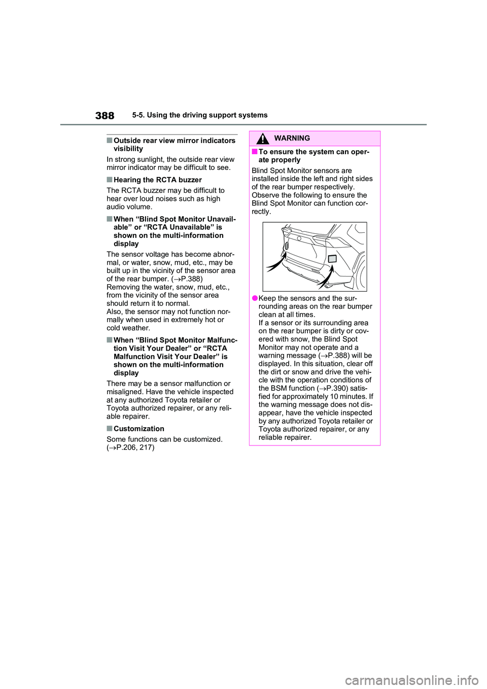
Blind Spot Monitor sensors are installed inside the left and right sides of the rear bumper respectively.
Observe the following to ensure the Blind Spot Monitor can function cor-rectly.
●Keep the sensors and the sur-rounding areas on the rear bumper
clean at all times. If a sensor or its surrounding area on the rear bumper is dirty or cov-
ered with snow, the Blind Spot Monitor may not operate and a warning message ( P.388) will be
displayed. In this situation, clear off the dirt or snow and drive the vehi-cle with the operation conditions of
the BSM function ( P.390) satis- fied for approximately 10 minutes. If the warning message does not dis-
appear, have the vehicle inspected by any authorized Toyota retailer or Toyota authorized repairer, or any
reliable repairer.
Page 391 of 718
389
5
5-5. Using the driving support systems
Driving
■Vehicles that can be detected
by the Blind Spot Monitor
The BSM function uses radar sen-
sors to detect the following vehicles
traveling in adjacent lanes and
advises the driver of the presence
of such vehicles via the indicators
on the outside rear view mirrors.
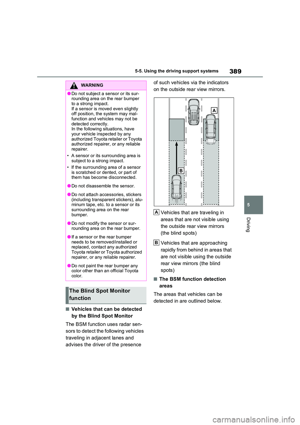
Vehicles that are traveling in
areas that are not visible using
the outside rear view mirrors
(the blind spots)
Vehicles that are approaching
rapidly from behind in areas that
are not visible using the outside
rear view mirrors (the blind
spots)
■The BSM function detection
areas
The areas that vehicles can be
detected in are outlined below.
WARNING
●Do not subject a sensor or its sur- rounding area on the rear bumper
to a strong impact. If a sensor is moved even slightly off position, the system may mal-
function and vehicles may not be detected correctly. In the following situations, have
your vehicle inspected by any authorized Toyota retailer or Toyota authorized repairer, or any reliable
repairer.
• A sensor or its surrounding area is subject to a strong impact.
• If the surrounding area of a sensor is scratched or dented, or part of them has become disconnected.
●Do not disassemble the sensor.
●Do not attach accessories, stickers (including transparent stickers), alu-minum tape, etc. to a sensor or its
surrounding area on the rear bumper.
●Do not modify the sensor or sur-rounding area on the rear bumper.
●If a sensor or the rear bumper needs to be removed/installed or replaced, contact any authorized
Toyota retailer or Toyota authorized repairer, or any reliable repairer.
●Do not paint the rear bumper any color other than an official Toyota color.
The Blind Spot Monitor
function
A
B
Page 392 of 718
3905-5. Using the driving support systems
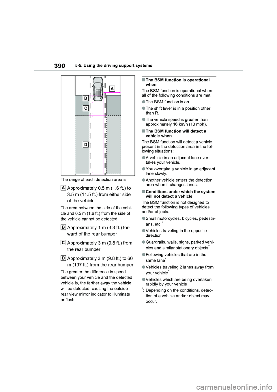
The range of each detection area is:
Approximately 0.5 m (1.6 ft.) to
3.5 m (11.5 ft.) from either side
of the vehicle
The area between the side of the vehi-
cle and 0.5 m (1.6 ft.) from the side of
the vehicle cannot be detected.
Approximately 1 m (3.3 ft.) for-
ward of the rear bumper
Approximately 3 m (9.8 ft.) from
the rear bumper
Approximately 3 m (9.8 ft.) to 60
m (197 ft.) from the rear bumper
The greater the difference in speed
between your vehicle and the detected
vehicle is, the farther away the vehicle
will be detected, causing the outside
rear view mirror indicator to illuminate
or flash.
■The BSM function is operational
when
The BSM function is operational when
all of the following conditions are met:
●The BSM function is on.
●The shift lever is in a position other
than R.
●The vehicle speed is greater than
approximately 16 km/h (10 mph).
■The BSM function will detect a
vehicle when
The BSM function will detect a vehicle
present in the detection area in the fol-
lowing situations:
●A vehicle in an adjacent lane over-
takes your vehicle.
●You overtake a vehicle in an adjacent
lane slowly.
●Another vehicle enters the detection
area when it changes lanes.
■Conditions under which the system
will not detect a vehicle
The BSM function is not designed to
detect the following types of vehicles
and/or objects:
●Small motorcycles, bicycles, pedestri-
ans, etc.*
●Vehicles traveling in the opposite
direction
●Guardrails, walls, signs, parked vehi-
cles and similar stationary objects*
●Following vehicles that are in the
same lane*
●Vehicles traveling 2 lanes away from
your vehicle*
●Vehicles which are being overtaken
rapidly by your vehicle
*: Depending on the conditions, detec-
tion of a vehicle and/or object may
occur.
A
B
C
D
Page 393 of 718

391
5 5-5. Using the driving support systems
Driving
■Conditions under which the system
may not function correctly
●The BSM function may not detect
vehicles correctly in the following situ-
ations:
• When the sensor is misaligned due to
a strong impact to the sensor or its
surrounding area
• When mud, snow, ice, a sticker, etc.,
is covering the sensor or surrounding
area on the rear bumper
• When driving on a road surface that is
wet with standing water during bad
weather, such as heavy rain, snow, or
fog
• When multiple vehicles are approach-
ing with only a small gap between
each vehicle
• When the distance between your vehi-
cle and a following vehicle is short
• When there is a significant difference
in speed between your vehicle and
the vehicle that enters the detection
area
• When the difference in speed
between your vehicle and another
vehicle is changing
• When a vehicle enters a detection
area traveling at about the same
speed as your vehicle
• As your vehicle starts from a stop, a
vehicle remains in the detection area
• When driving up and down consecu-
tive steep inclines, such as hills, dips
in the road, etc.
• When driving on roads with sharp
bends, consecutive curves, or uneven
surfaces
• When vehicle lanes are wide, or when
driving on the edge of a lane, and the
vehicle in an adjacent lane is far away
from your vehicle
• When an accessory (such as a bicycle
carrier) is installed to the rear of the
vehicle
• When there is a significant difference
in height between your vehicle and
the vehicle that enters the detection
area
• Immediately after the BSM func-
tion/RCTA function are turned on
• When towing a trailer
●Instances of the BSM function unnec-
essarily detecting a vehicle and/or
object may increase in the following
situations:
• When the sensor is misaligned due to
a strong impact to the sensor or its
surrounding area
• When the distance between your vehi-
cle and a guardrail, wall, etc. that
enters the detection area is short
• When driving up and down consecu-
tive steep inclines, such as hills, dips
in the road, etc.
• When vehicle lanes are narrow, or
when driving on the edge of a lane,
and a vehicle traveling in a lane other
than the adjacent lanes enters the
detection area
• When driving on roads with sharp
bends, consecutive curves, or uneven
surfaces
• When the tires are slipping or spinning
• When the distance between your vehi-
cle and a following vehicle is short
• When an accessory (such as a bicycle
carrier) is installed to the rear of the
vehicle
• When the vehicle throws up water or
snow behind.
■Operation of the RCTA func-
tion
The RCTA function uses radar sen-
sors to detect vehicles approaching
from the right or left at the rear of
the vehicle and alerts the driver of
the presence of such vehicles by
flashing the outside rear view mirror
indicators and sounding a buzzer.
The Rear Crossing Traffic
Alert function
Page 432 of 718
4306-1. Using the air conditioning system and defogger
6-1.Using the a ir c onditioning sys te m and de fog ger
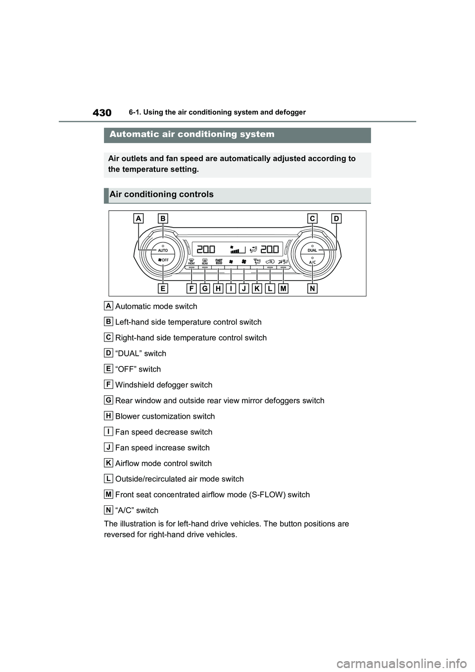
Automatic mode switch
Left-hand side temperature control switch
Right-hand side temperature control switch
“DUAL” switch
“OFF” switch
Windshield defogger switch
Rear window and outside rear view mirror defoggers switch
Blower customization switch
Fan speed decrease switch
Fan speed increase switch
Airflow mode control switch
Outside/recirculated air mode switch
Front seat concentrated airflow mode (S-FLOW) switch
“A/C” switch
The illustration is for left-hand drive vehicles. The button positions are
reversed for right-hand drive vehicles.
Automatic air conditioning system
Air outlets and fan speed are automatically adjusted according to
the temperature setting.
Air conditioning controls
A
B
C
D
E
F
G
H
I
J
K
L
M
N
Page 434 of 718
4326-1. Using the air conditioning system and defogger
switch to outside air mode if the recircu-
lated air mode is used. (It may switch
automatically.)
To defog the windshield and the side
windows quickly, turn the air flow and
temperature up.
To return to the previous mode, press
the windshield defogger switch again
when the windshield is defogged.
When the windshield defogger switch is
on, the indicator illuminates on the
windshield defogger switch.
■Defogging the rear window
and outside rear view mirrors
Defoggers are used to defog the
rear window, and to remove rain-
drops, dew and frost from the out-
side rear view mirrors.
Press the rear window and outside
rear view mirror defoggers switch.
The defoggers will automatically turn off
after 15 minutes.
When the rear window and outside rear
view mirror defoggers switch is on, the
indicator illuminates on the rear window
and outside rear view mirror defoggers
switch.
■Blower customization
The fan speed can be adjusted
according to your preference.
1Press the automatic mode or
airflow mode control switch.
2Press the blower customization
switch.
3Each time the blower customi-
zation switch is pressed, the fan
speed changes as follows.
Normal “ECO” “FAST”
■Heating
●In HV mode, the gasoline engine may
operate in order to extract heat from
the engine coolant via the heater.
●In EV mode, heating is done by a heat
pump system.
• When the outside temperature is low
or it is snowing, compared to conven-
tional vehicles, heating may be less
effective and warm air may not come
out.
• When the outside heat exchanger is
frosted over, fan speed declines and it
may become harder to heat the inte-
rior. However, it is not a malfunction.
In this situation, the air temperature
from the outlets may not change even
though the set temperature is raised.
• If frost has formed of the outside heat
exchanger, the heating performance
will decline. The frost can be removed
from the outside heat exchanger by
operating the Remote Air Conditioning
System before driving (P.438).
When frosted over, the heating opera-
tion of the Remote Air Conditioning
System starts after defrosting.
• When “AUTO” switch is turned on, the
heating is controlled optimally. There-
fore, the set heating performance may
not be achieved even if the fan speed
setting is increased.
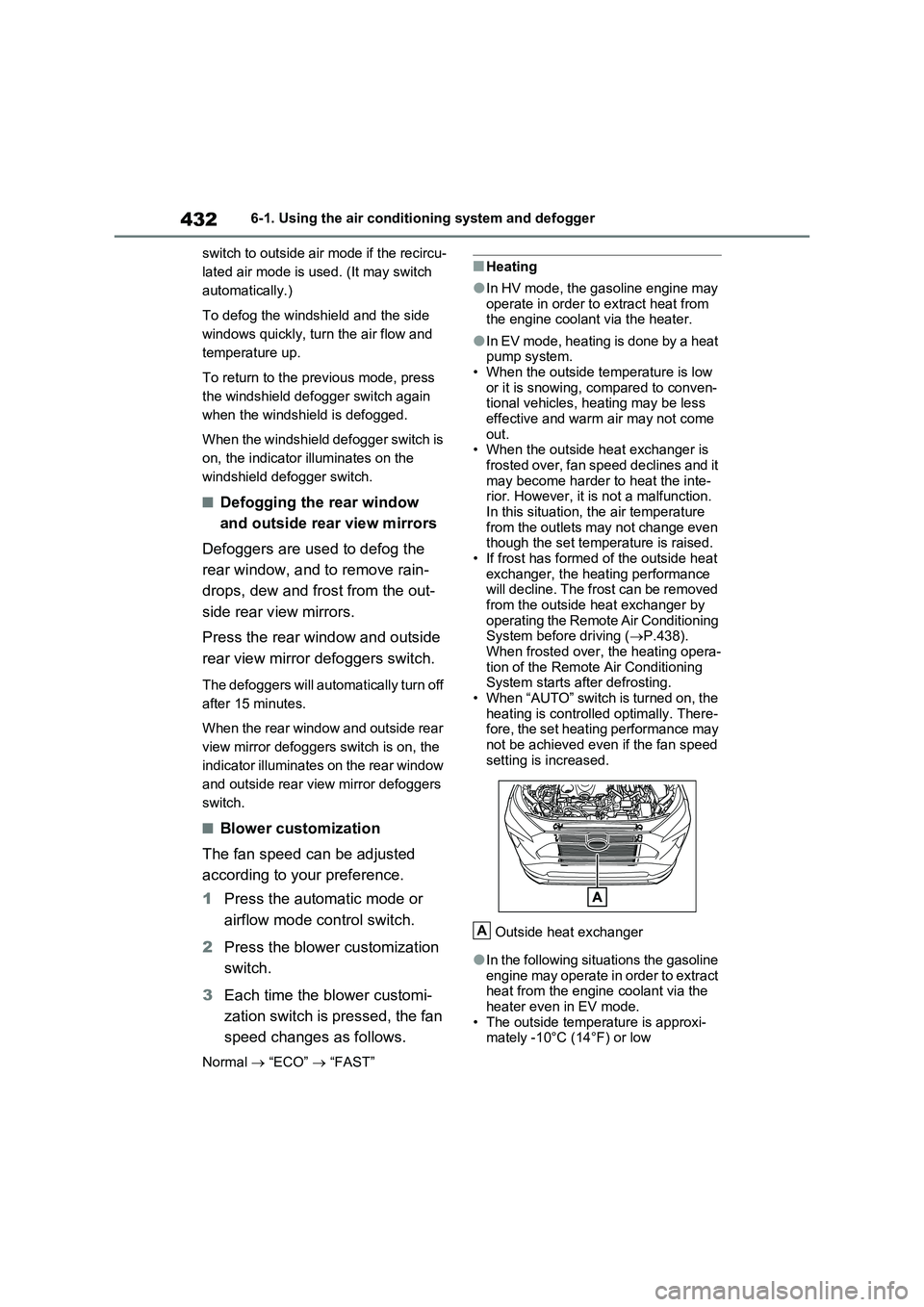
Outside heat exchanger
●In the following situations the gasoline
engine may operate in order to extract
heat from the engine coolant via the
heater even in EV mode.
• The outside temperature is approxi-
mately -10°C (14°F) or low
A
Page 436 of 718
4346-1. Using the air conditioning system and defogger
ing system to the outside air mode.
●During use, various odors from inside and outside the vehicle may enter into
and accumulate in the air conditioning system. This may then cause odor to be emitted from the vents.
●To reduce potential odors from occur-ring:
• It is recommended that the air condi- tioning system be set to outside air mode prior to turning the vehicle off.
• The start timing of the blower may be delayed for a short period of time immediately after the air conditioning
system is started in automatic mode.
●When parking, the system automati-
cally switches to outside air mode to encourage better air circulation throughout the vehicle, helping to
reduce odors that occur when starting the vehicle.
■Using the voice control system (if equipped)
Air conditioning system can be operated using the voice control system. For details regarding the voice control sys-
tem, refer to the “Multimedia owner’s manual”.
■Air conditioning filter
P.500
■Noise from air conditioning system
Approximately 90 seconds after the power switch turned to OFF, you may hear sound coming from air conditioning
system. This is the sound of a air condi- tioning system initialize and, it does not indicate a malfunction.
■Customization
Settings (e.g. A/C Auto switch opera- tion) can be changed.(Customizable features: P.607)
1Press the “AUTO” switch.
The dehumidification function begins to operate. Air outlets and fan speed are automatically adjusted according to the
temperature setting and humidity.
2 Adjust the temperature setting.
3 To stop the operation, press the
“OFF” switch.
WARNING
■Cautions for using “My Room Mode”
Do not leave children, people who need assistance, or pets inside the vehicle. The system may turn off
automatically and the interior tem- perature may become high or low, resulting in heat stroke, dehydration
or hypothermia. Failure to do so may result in death or serious injury.
■To prevent the windshield from fogging up
Do not use the windshield defogger
switch during cool air operation in extremely humid weather.The difference between the tempera-
ture of the outside air and that of the windshield can cause the outer sur-face of the windshield to fog up,
blocking your vision.
■When the outside rear view mir-
ror defoggers are operating
Do not touch the rear view mirror sur- faces when the outside rear view mir-
ror defoggers are on.
NOTICE
■To prevent 12-volt battery dis- charge
Do not leave the air conditioning sys-
tem on longer than necessary when the hybrid system is off.
Using automatic mode