TOYOTA SIENNA 2007 Service Repair Manual
Manufacturer: TOYOTA, Model Year: 2007, Model line: SIENNA, Model: TOYOTA SIENNA 2007Pages: 3000, PDF Size: 52.26 MB
Page 1141 of 3000
FU–202GR-FE FUEL – FUEL INJECTOR
FU
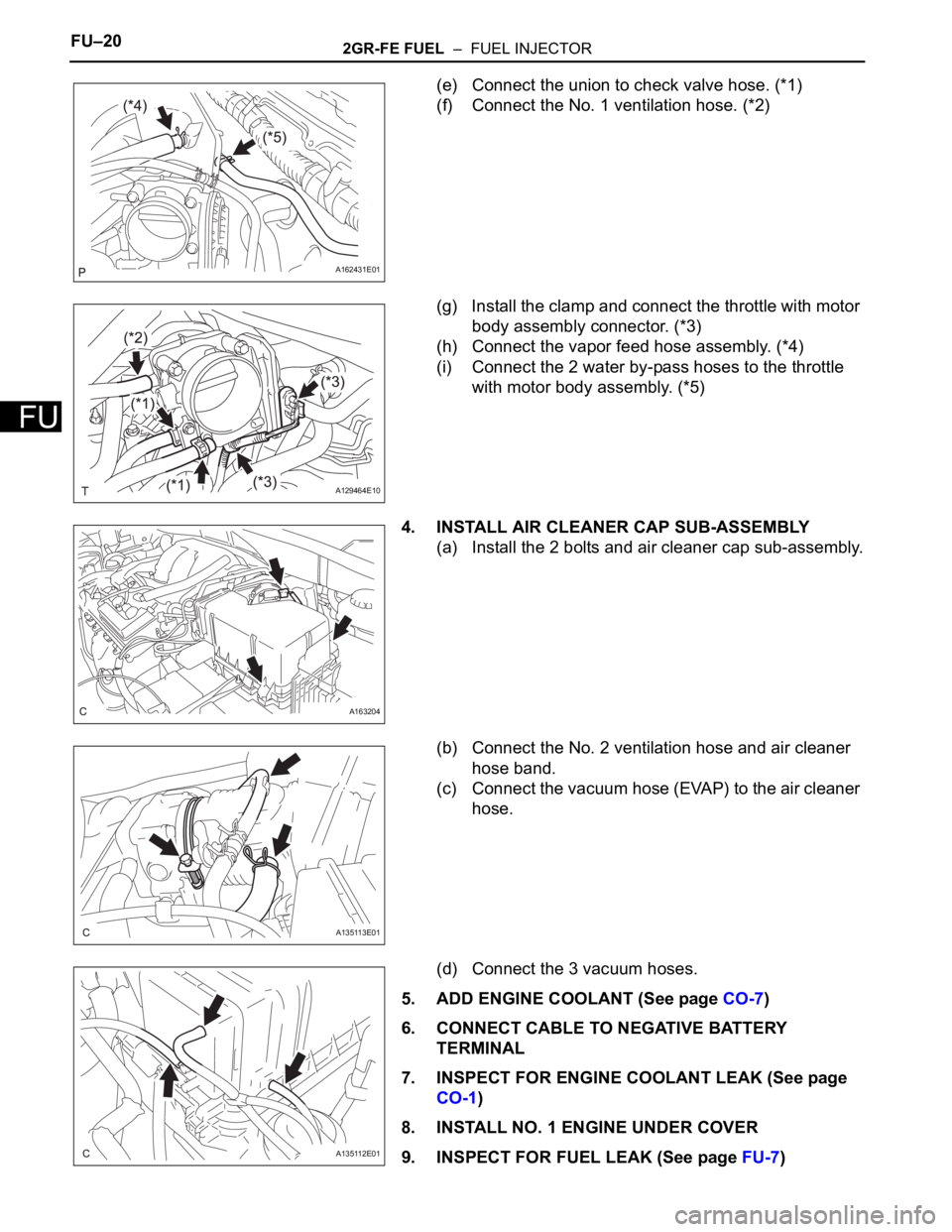
(e) Connect the union to check valve hose. (*1)
(f) Connect the No. 1 ventilation hose. (*2)
(g) Install the clamp and connect the throttle with motor
body assembly connector. (*3)
(h) Connect the vapor feed hose assembly. (*4)
(i) Connect the 2 water by-pass hoses to the throttle
with motor body assembly. (*5)
4. INSTALL AIR CLEANER CAP SUB-ASSEMBLY
(a) Install the 2 bolts and air cleaner cap sub-assembly.
(b) Connect the No. 2 ventilation hose and air cleaner
hose band.
(c) Connect the vacuum hose (EVAP) to the air cleaner
hose.
(d) Connect the 3 vacuum hoses.
5. ADD ENGINE COOLANT (See page CO-7)
6. CONNECT CABLE TO NEGATIVE BATTERY
TERMINAL
7. INSPECT FOR ENGINE COOLANT LEAK (See page
CO-1)
8. INSTALL NO. 1 ENGINE UNDER COVER
9. INSPECT FOR FUEL LEAK (See page FU-7)
A162431E01
A129464E10
A163204
A135113E01
A135112E01
Page 1142 of 3000
2GR-FE FUEL – FUEL INJECTORFU–21
FU
10. INSTALL V-BANK COVER SUB-ASSEMBLY (See
page EM-63)
11. INSTALL COWL TOP PANEL SUB-ASSEMBLY
OUTER FRONT
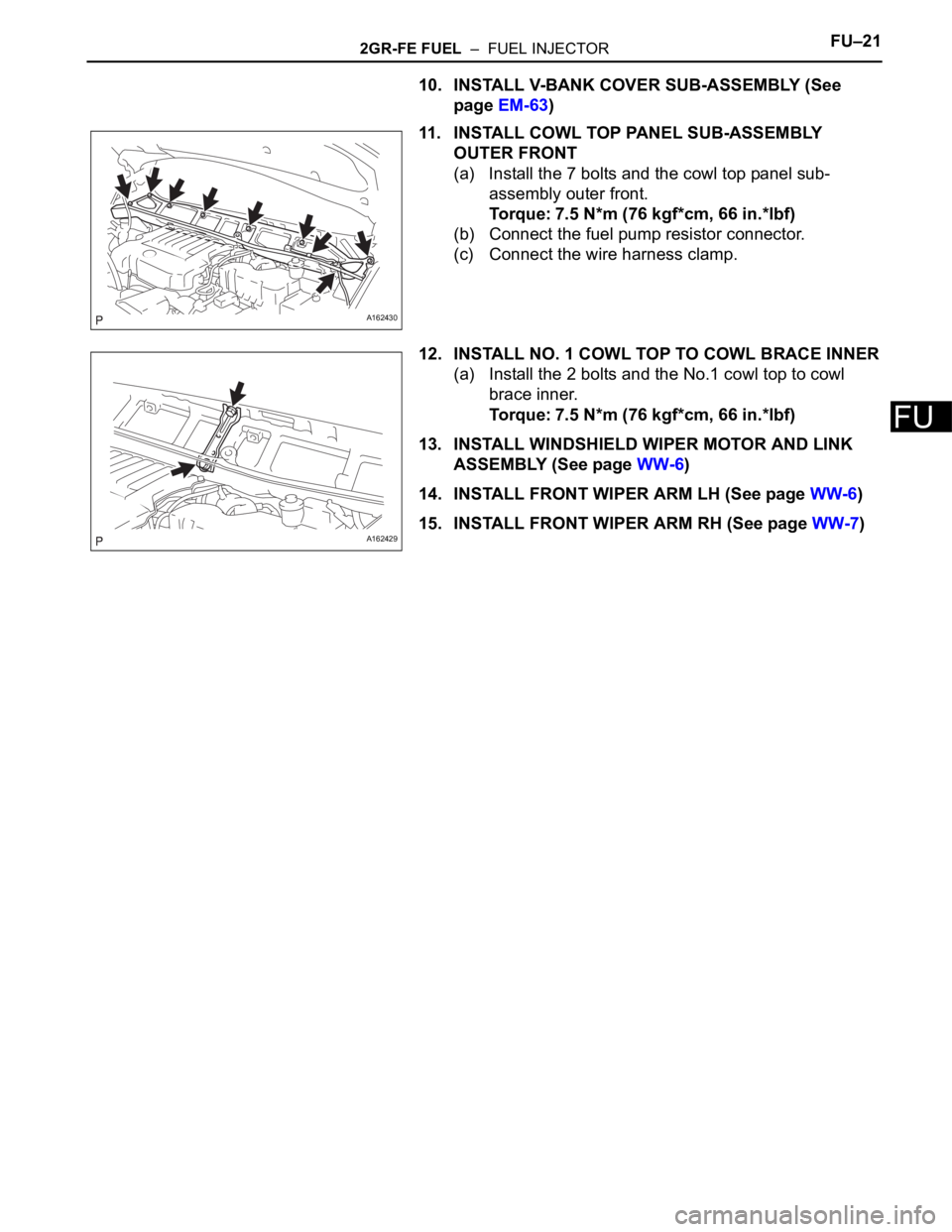
(a) Install the 7 bolts and the cowl top panel sub-
assembly outer front.
Torque: 7.5 N*m (76 kgf*cm, 66 in.*lbf)
(b) Connect the fuel pump resistor connector.
(c) Connect the wire harness clamp.
12. INSTALL NO. 1 COWL TOP TO COWL BRACE INNER
(a) Install the 2 bolts and the No.1 cowl top to cowl
brace inner.
Torque: 7.5 N*m (76 kgf*cm, 66 in.*lbf)
13. INSTALL WINDSHIELD WIPER MOTOR AND LINK
ASSEMBLY (See page WW-6)
14. INSTALL FRONT WIPER ARM LH (See page WW-6)
15. INSTALL FRONT WIPER ARM RH (See page WW-7)
A162430
A162429
Page 1143 of 3000
2GR-FE FUEL – FUEL PRESSURE PULSATION DAMPERFU–25
FU
REMOVAL
1. DISCHARGE FUEL SYSTEM PRESSURE
HINT:
See page FU-1.
2. DISCONNECT CABLE FROM NEGATIVE BATTERY
TERMINAL
3. REMOVE NO. 1 ENGINE UNDER COVER
4. DRAIN ENGINE COOLANT (See page CO-6)
5. REMOVE FRONT WIPER ARM HEAD CAP (See page
WW-4)
6. REMOVE FRONT WIPER ARM RH (See page WW-4)
7. REMOVE FRONT WIPER ARM LH (See page WW-4)
8. REMOVE COWL TOP VENTILATOR LOUVER SUB-
ASSEMBLY (See page WW-4)
9. REMOVE WINDSHIELD WIPER MOTOR AND LINK
ASSEMBLY (See page WW-4)
10. REMOVE NO. 1 COWL TOP TO COWL BRACE INNER
(See page FU-13)
11. REMOVE COWL TOP PANEL SUB-ASSEMBLY
OUTER FRONT (See page FU-13)
12. REMOVE V-BANK COVER SUB-ASSEMBLY (See
page EM-28)
13. REMOVE AIR CLEANER CAP SUB-ASSEMBLY (See
page FU-13)
14. REMOVE INTAKE AIR SURGE TANK ASSEMBLY
(See page FU-14)
15. REMOVE FUEL PRESSURE PULSATION DAMPER
ASSEMBLY
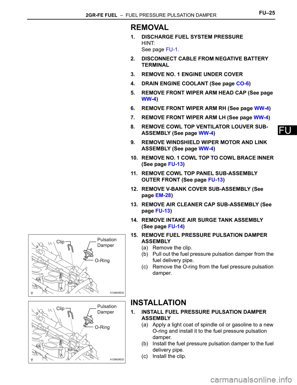
(a) Remove the clip.
(b) Pull out the fuel pressure pulsation damper from the
fuel delivery pipe.
(c) Remove the O-ring from the fuel pressure pulsation
damper.
INSTALLATION
1. INSTALL FUEL PRESSURE PULSATION DAMPER
ASSEMBLY
(a) Apply a light coat of spindle oil or gasoline to a new
O-ring and install it to the fuel pressure pulsation
damper.
(b) Install the fuel pressure pulsation damper to the fuel
delivery pipe.
(c) Install the clip.
A129609E02
A129609E02
Page 1144 of 3000
FU–262GR-FE FUEL – FUEL PRESSURE PULSATION DAMPER
FU
2. INSTALL INTAKE AIR SURGE TANK ASSEMBLY (See
page FU-19)
3. INSTALL AIR CLEANER CAP SUB-ASSEMBLY (See
page FU-20)
4. ADD ENGINE COOLANT (See page CO-7)
5. CONNECT CABLE TO NEGATIVE BATTERY
TERMINAL
6. INSPECT FOR ENGINE COOLANT LEAK (See page
CO-1)
7. INSTALL NO. 1 ENGINE UNDER COVER
8. INSPECT FOR FUEL LEAK (See page FU-7)
9. INSTALL V-BANK COVER SUB-ASSEMBLY (See
page EM-63)
10. INSTALL COWL TOP PANEL SUB-ASSEMBLY
OUTER FRONT (See page FU-21)
11. INSTALL NO. 1 COWL TOP TO COWL BRACE INNER
(See page FU-21)
12. INSTALL WINDSHIELD WIPER MOTOR AND LINK
ASSEMBLY (See page WW-6)
13. INSTALL FRONT WIPER ARM LH (See page WW-6)
14. INSTALL FRONT WIPER ARM RH (See page WW-7)
Page 1145 of 3000
FU–302GR-FE FUEL – FUEL PUMP
FU
REMOVAL
1. DISCHARGE FUEL SYSTEM PRESSURE
(See page FU-1)
2. REMOVE CHARCOAL CANISTER PROTECTOR
(a) Remove the 6bolts and the charcoal canister
protector.
3. REMOVE REAR FLOOR NO. 2 CROSSMEMBER
BRACE LH (See page FU-41)
4. REMOVE FUEL TANK FILLER HOSE COVER (See
page FU-41)
5. REMOVE FUEL TANK ASSEMBLY (See page FU-41)
Page 1146 of 3000
2GR-FE FUEL – FUEL PUMPFU–31
FU
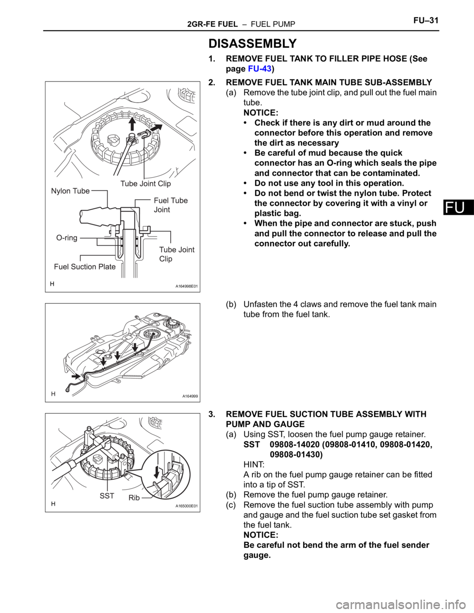
DISASSEMBLY
1. REMOVE FUEL TANK TO FILLER PIPE HOSE (See
page FU-43)
2. REMOVE FUEL TANK MAIN TUBE SUB-ASSEMBLY
(a) Remove the tube joint clip, and pull out the fuel main
tube.
NOTICE:
• Check if there is any dirt or mud around the
connector before this operation and remove
the dirt as necessary
• Be careful of mud because the quick
connector has an O-ring which seals the pipe
and connector that can be contaminated.
• Do not use any tool in this operation.
• Do not bend or twist the nylon tube. Protect
the connector by covering it with a vinyl or
plastic bag.
• When the pipe and connector are stuck, push
and pull the connector to release and pull the
connector out carefully.
(b) Unfasten the 4 claws and remove the fuel tank main
tube from the fuel tank.
3. REMOVE FUEL SUCTION TUBE ASSEMBLY WITH
PUMP AND GAUGE
(a) Using SST, loosen the fuel pump gauge retainer.
SST 09808-14020 (09808-01410, 09808-01420,
09808-01430)
HINT:
A rib on the fuel pump gauge retainer can be fitted
into a tip of SST.
(b) Remove the fuel pump gauge retainer.
(c) Remove the fuel suction tube assembly with pump
and gauge and the fuel suction tube set gasket from
the fuel tank.
NOTICE:
Be careful not bend the arm of the fuel sender
gauge.
A164998E01
A164999
A165000E01
Page 1147 of 3000
FU–322GR-FE FUEL – FUEL PUMP
FU
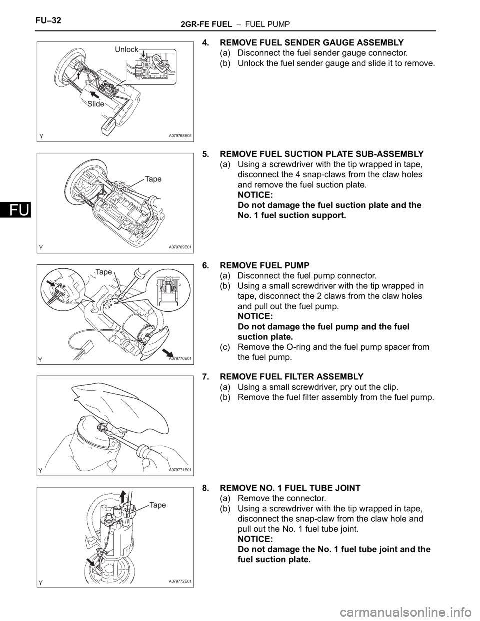
4. REMOVE FUEL SENDER GAUGE ASSEMBLY
(a) Disconnect the fuel sender gauge connector.
(b) Unlock the fuel sender gauge and slide it to remove.
5. REMOVE FUEL SUCTION PLATE SUB-ASSEMBLY
(a) Using a screwdriver with the tip wrapped in tape,
disconnect the 4 snap-claws from the claw holes
and remove the fuel suction plate.
NOTICE:
Do not damage the fuel suction plate and the
No. 1 fuel suction support.
6. REMOVE FUEL PUMP
(a) Disconnect the fuel pump connector.
(b) Using a small screwdriver with the tip wrapped in
tape, disconnect the 2 claws from the claw holes
and pull out the fuel pump.
NOTICE:
Do not damage the fuel pump and the fuel
suction plate.
(c) Remove the O-ring and the fuel pump spacer from
the fuel pump.
7. REMOVE FUEL FILTER ASSEMBLY
(a) Using a small screwdriver, pry out the clip.
(b) Remove the fuel filter assembly from the fuel pump.
8. REMOVE NO. 1 FUEL TUBE JOINT
(a) Remove the connector.
(b) Using a screwdriver with the tip wrapped in tape,
disconnect the snap-claw from the claw hole and
pull out the No. 1 fuel tube joint.
NOTICE:
Do not damage the No. 1 fuel tube joint and the
fuel suction plate.
A079768E05
A079769E01
A079770E01
A079771E01
A079772E01
Page 1148 of 3000
FU–302GR-FE FUEL – FUEL PUMP
FU
REMOVAL
1. DISCHARGE FUEL SYSTEM PRESSURE
(See page FU-1)
2. REMOVE CHARCOAL CANISTER PROTECTOR
(a) Remove the 6bolts and the charcoal canister
protector.
3. REMOVE REAR FLOOR NO. 2 CROSSMEMBER
BRACE LH (See page FU-41)
4. REMOVE FUEL TANK FILLER HOSE COVER (See
page FU-41)
5. REMOVE FUEL TANK ASSEMBLY (See page FU-41)
Page 1149 of 3000
2GR-FE FUEL – FUEL PUMPFU–31
FU
DISASSEMBLY
1. REMOVE FUEL TANK TO FILLER PIPE HOSE (See
page FU-43)
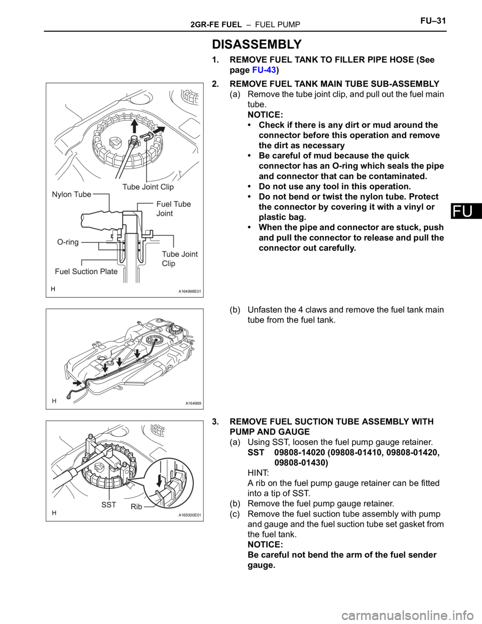
2. REMOVE FUEL TANK MAIN TUBE SUB-ASSEMBLY
(a) Remove the tube joint clip, and pull out the fuel main
tube.
NOTICE:
• Check if there is any dirt or mud around the
connector before this operation and remove
the dirt as necessary
• Be careful of mud because the quick
connector has an O-ring which seals the pipe
and connector that can be contaminated.
• Do not use any tool in this operation.
• Do not bend or twist the nylon tube. Protect
the connector by covering it with a vinyl or
plastic bag.
• When the pipe and connector are stuck, push
and pull the connector to release and pull the
connector out carefully.
(b) Unfasten the 4 claws and remove the fuel tank main
tube from the fuel tank.
3. REMOVE FUEL SUCTION TUBE ASSEMBLY WITH
PUMP AND GAUGE
(a) Using SST, loosen the fuel pump gauge retainer.
SST 09808-14020 (09808-01410, 09808-01420,
09808-01430)
HINT:
A rib on the fuel pump gauge retainer can be fitted
into a tip of SST.
(b) Remove the fuel pump gauge retainer.
(c) Remove the fuel suction tube assembly with pump
and gauge and the fuel suction tube set gasket from
the fuel tank.
NOTICE:
Be careful not bend the arm of the fuel sender
gauge.
A164998E01
A164999
A165000E01
Page 1150 of 3000
FU–322GR-FE FUEL – FUEL PUMP
FU
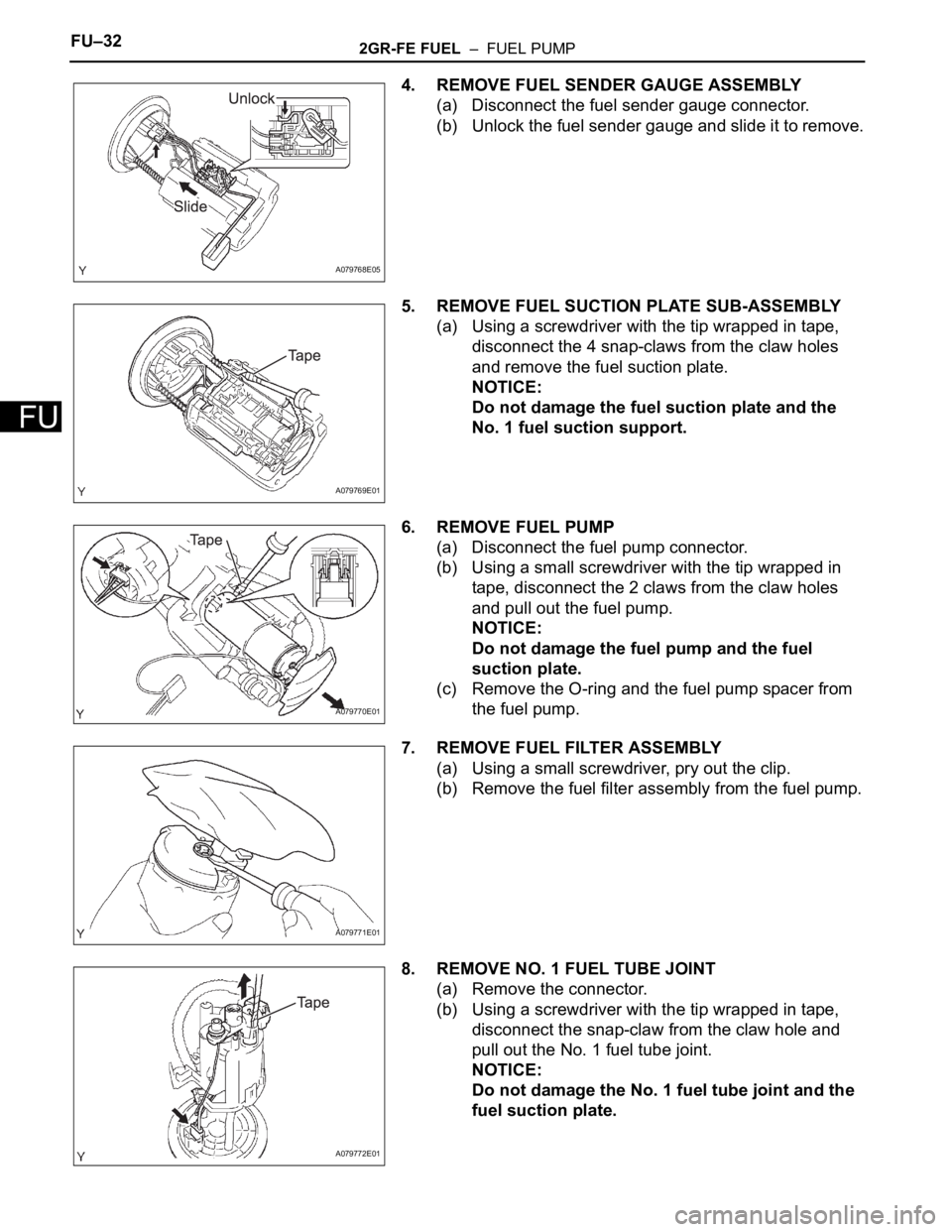
4. REMOVE FUEL SENDER GAUGE ASSEMBLY
(a) Disconnect the fuel sender gauge connector.
(b) Unlock the fuel sender gauge and slide it to remove.
5. REMOVE FUEL SUCTION PLATE SUB-ASSEMBLY
(a) Using a screwdriver with the tip wrapped in tape,
disconnect the 4 snap-claws from the claw holes
and remove the fuel suction plate.
NOTICE:
Do not damage the fuel suction plate and the
No. 1 fuel suction support.
6. REMOVE FUEL PUMP
(a) Disconnect the fuel pump connector.
(b) Using a small screwdriver with the tip wrapped in
tape, disconnect the 2 claws from the claw holes
and pull out the fuel pump.
NOTICE:
Do not damage the fuel pump and the fuel
suction plate.
(c) Remove the O-ring and the fuel pump spacer from
the fuel pump.
7. REMOVE FUEL FILTER ASSEMBLY
(a) Using a small screwdriver, pry out the clip.
(b) Remove the fuel filter assembly from the fuel pump.
8. REMOVE NO. 1 FUEL TUBE JOINT
(a) Remove the connector.
(b) Using a screwdriver with the tip wrapped in tape,
disconnect the snap-claw from the claw hole and
pull out the No. 1 fuel tube joint.
NOTICE:
Do not damage the No. 1 fuel tube joint and the
fuel suction plate.
A079768E05
A079769E01
A079770E01
A079771E01
A079772E01