TOYOTA SIENNA 2007 Service Repair Manual
Manufacturer: TOYOTA, Model Year: 2007, Model line: SIENNA, Model: TOYOTA SIENNA 2007Pages: 3000, PDF Size: 52.26 MB
Page 2751 of 3000
PS–40POWER STEERING – RACK AND PINION POWER STEERING GEAR
PS
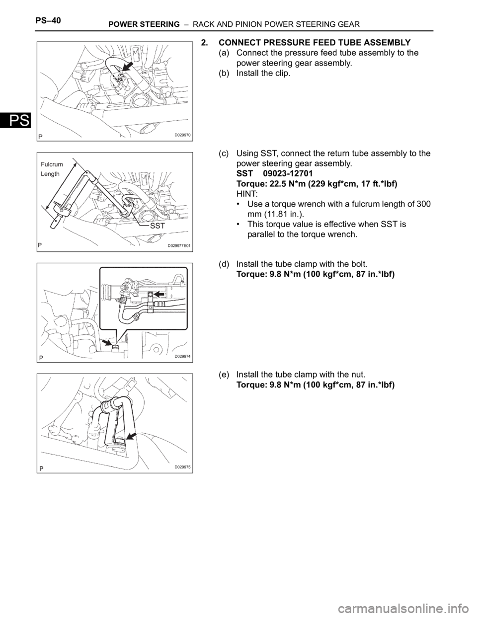
2. CONNECT PRESSURE FEED TUBE ASSEMBLY
(a) Connect the pressure feed tube assembly to the
power steering gear assembly.
(b) Install the clip.
(c) Using SST, connect the return tube assembly to the
power steering gear assembly.
SST 09023-12701
Torque: 22.5 N*m (229 kgf*cm, 17 ft.*lbf)
HINT:
• Use a torque wrench with a fulcrum length of 300
mm (11.81 in.).
• This torque value is effective when SST is
parallel to the torque wrench.
(d) Install the tube clamp with the bolt.
Torque: 9.8 N*m (100 kgf*cm, 87 in.*lbf)
(e) Install the tube clamp with the nut.
Torque: 9.8 N*m (100 kgf*cm, 87 in.*lbf)
D029970
D029977E01
D029974
D029975
Page 2752 of 3000
POWER STEERING – RACK AND PINION POWER STEERING GEARPS–41
PS
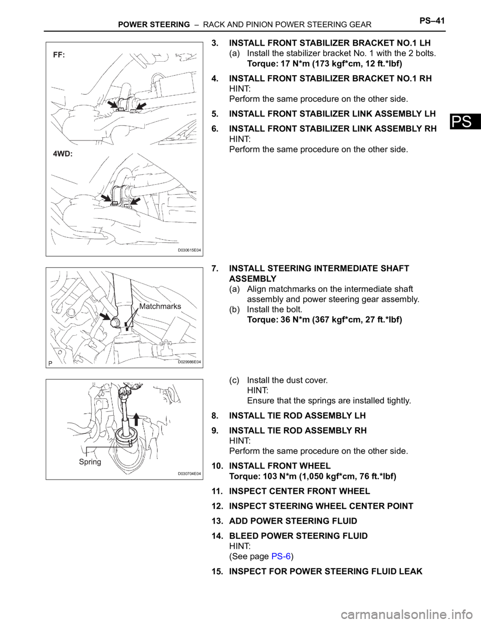
3. INSTALL FRONT STABILIZER BRACKET NO.1 LH
(a) Install the stabilizer bracket No. 1 with the 2 bolts.
Torque: 17 N*m (173 kgf*cm, 12 ft.*lbf)
4. INSTALL FRONT STABILIZER BRACKET NO.1 RH
HINT:
Perform the same procedure on the other side.
5. INSTALL FRONT STABILIZER LINK ASSEMBLY LH
6. INSTALL FRONT STABILIZER LINK ASSEMBLY RH
HINT:
Perform the same procedure on the other side.
7. INSTALL STEERING INTERMEDIATE SHAFT
ASSEMBLY
(a) Align matchmarks on the intermediate shaft
assembly and power steering gear assembly.
(b) Install the bolt.
Torque: 36 N*m (367 kgf*cm, 27 ft.*lbf)
(c) Install the dust cover.
HINT:
Ensure that the springs are installed tightly.
8. INSTALL TIE ROD ASSEMBLY LH
9. INSTALL TIE ROD ASSEMBLY RH
HINT:
Perform the same procedure on the other side.
10. INSTALL FRONT WHEEL
Torque: 103 N*m (1,050 kgf*cm, 76 ft.*lbf)
11. INSPECT CENTER FRONT WHEEL
12. INSPECT STEERING WHEEL CENTER POINT
13. ADD POWER STEERING FLUID
14. BLEED POWER STEERING FLUID
HINT:
(See page PS-6)
15. INSPECT FOR POWER STEERING FLUID LEAK
D030615E04
D029986E04
D030704E04
Page 2753 of 3000

PS–42POWER STEERING – RACK AND PINION POWER STEERING GEAR
PS
16. INSPECT AND ADJUST FRONT WHEEL ALIGNMENT
HINT:
(See page SP-4)
Page 2754 of 3000
AC–6AIR CONDITIONING – AIR CONDITIONING SYSTEM (for Automatic Air Conditioning Sys-
tem)
AC
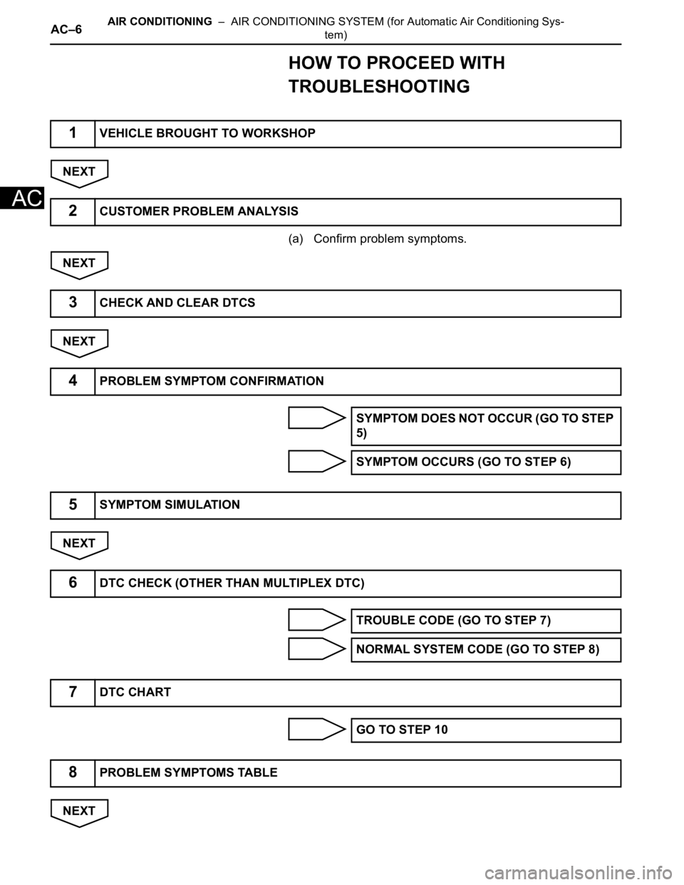
HOW TO PROCEED WITH
TROUBLESHOOTING
NEXT
(a) Confirm problem symptoms.
NEXT
NEXT
NEXT
NEXT
1VEHICLE BROUGHT TO WORKSHOP
2CUSTOMER PROBLEM ANALYSIS
3CHECK AND CLEAR DTCS
4PROBLEM SYMPTOM CONFIRMATION
SYMPTOM DOES NOT OCCUR (GO TO STEP
5)
SYMPTOM OCCURS (GO TO STEP 6)
5SYMPTOM SIMULATION
6DTC CHECK (OTHER THAN MULTIPLEX DTC)
TROUBLE CODE (GO TO STEP 7)
NORMAL SYSTEM CODE (GO TO STEP 8)
7DTC CHART
GO TO STEP 10
8PROBLEM SYMPTOMS TABLE
Page 2755 of 3000
AIR CONDITIONING – AIR CONDITIONING SYSTEM (for Automatic Air Conditioning Sys-
tem)AC–7
AC
NEXT
NEXT
NEXT
NEXT
NEXT
9TERMINALS OF ECU
10CIRCUIT INSPECTION
11IDENTIFICATION OF PROBLEM
12REPAIR OR REPLACE
13CONFIRMATION TEST
END
Page 2756 of 3000
AC–8AIR CONDITIONING – AIR CONDITIONING SYSTEM (for Automatic Air Conditioning Sys-
tem)
AC
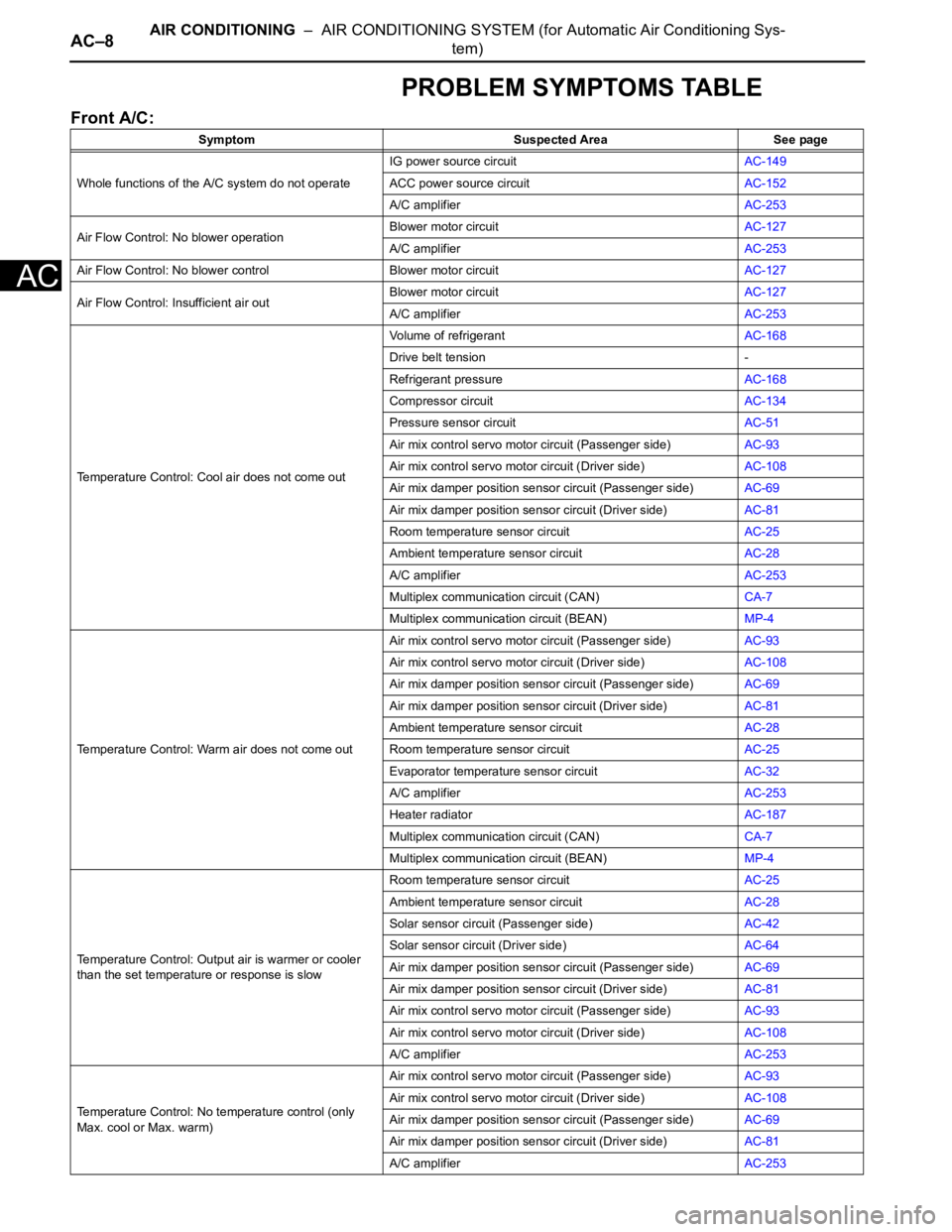
PROBLEM SYMPTOMS TABLE
Front A/C:
Symptom Suspected Area See page
Whole functions of the A/C system do not operateIG power source circuitAC-149
ACC power source circuitAC-152
A/C amplifierAC-253
Air Flow Control: No blower operationBlower motor circuitAC-127
A/C amplifierAC-253
Air Flow Control: No blower control Blower motor circuitAC-127
Air Flow Control: Insufficient air outBlower motor circuitAC-127
A/C amplifierAC-253
Temperature Control: Cool air does not come outVolume of refrigerantAC-168
Drive belt tension -
Refrigerant pressureAC-168
Compressor circuitAC-134
Pressure sensor circuitAC-51
Air mix control servo motor circuit (Passenger side)AC-93
Air mix control servo motor circuit (Driver side)AC-108
Air mix damper position sensor circuit (Passenger side)AC-69
Air mix damper position sensor circuit (Driver side)AC-81
Room temperature sensor circuitAC-25
Ambient temperature sensor circuitAC-28
A/C amplifierAC-253
Multiplex communication circuit (CAN)CA-7
Multiplex communication circuit (BEAN)MP-4
Temperature Control: Warm air does not come outAir mix control servo motor circuit (Passenger side)AC-93
Air mix control servo motor circuit (Driver side)AC-108
Air mix damper position sensor circuit (Passenger side)AC-69
Air mix damper position sensor circuit (Driver side)AC-81
Ambient temperature sensor circuitAC-28
Room temperature sensor circuitAC-25
Evaporator temperature sensor circuitAC-32
A/C amplifierAC-253
Heater radiatorAC-187
Multiplex communication circuit (CAN)CA-7
Multiplex communication circuit (BEAN)MP-4
Temperature Control: Output air is warmer or cooler
than the set temperature or response is slowRoom temperature sensor circuitAC-25
Ambient temperature sensor circuitAC-28
Solar sensor circuit (Passenger side)AC-42
Solar sensor circuit (Driver side)AC-64
Air mix damper position sensor circuit (Passenger side)AC-69
Air mix damper position sensor circuit (Driver side)AC-81
Air mix control servo motor circuit (Passenger side)AC-93
Air mix control servo motor circuit (Driver side)AC-108
A/C amplifierAC-253
Temperature Control: No temperature control (only
Max. cool or Max. warm)Air mix control servo motor circuit (Passenger side)AC-93
Air mix control servo motor circuit (Driver side)AC-108
Air mix damper position sensor circuit (Passenger side)
AC-69
Air mix damper position sensor circuit (Driver side)AC-81
A/C amplifierAC-253
Page 2757 of 3000
AIR CONDITIONING – AIR CONDITIONING SYSTEM (for Automatic Air Conditioning Sys-
tem)AC–9
AC
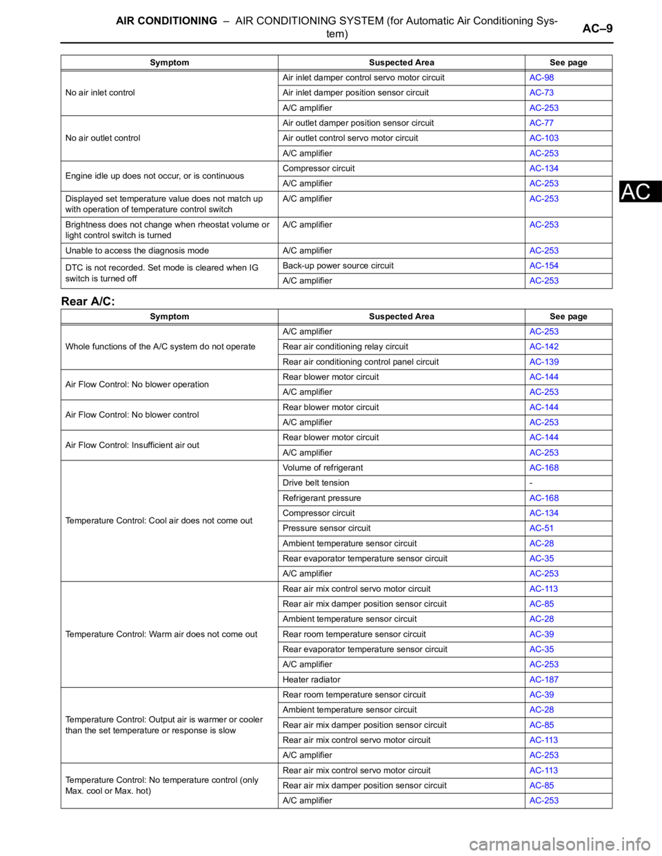
Rear A/C:
No air inlet controlAir inlet damper control servo motor circuitAC-98
Air inlet damper position sensor circuitAC-73
A/C amplifierAC-253
No air outlet controlAir outlet damper position sensor circuitAC-77
Air outlet control servo motor circuitAC-103
A/C amplifierAC-253
Engine idle up does not occur, or is continuousCompressor circuitAC-134
A/C amplifierAC-253
Displayed set temperature value does not match up
with operation of temperature control switchA/C amplifierAC-253
Brightness does not change when rheostat volume or
light control switch is turnedA/C amplifierAC-253
Unable to access the diagnosis mode A/C amplifierAC-253
DTC is not recorded. Set mode is cleared when IG
switch is turned offBack-up power source circuitAC-154
A/C amplifierAC-253
Symptom Suspected Area See page
Whole functions of the A/C system do not operateA/C amplifierAC-253
Rear air conditioning relay circuitAC-142
Rear air conditioning control panel circuitAC-139
Air Flow Control: No blower operationRear blower motor circuitAC-144
A/C amplifierAC-253
Air Flow Control: No blower controlRear blower motor circuitAC-144
A/C amplifierAC-253
Air Flow Control: Insufficient air outRear blower motor circuitAC-144
A/C amplifierAC-253
Temperature Control: Cool air does not come outVolume of refrigerantAC-168
Drive belt tension -
Refrigerant pressureAC-168
Compressor circuitAC-134
Pressure sensor circuitAC-51
Ambient temperature sensor circuitAC-28
Rear evaporator temperature sensor circuitAC-35
A/C amplifierAC-253
Temperature Control: Warm air does not come outRear air mix control servo motor circuitAC-113
Rear air mix damper position sensor circuitAC-85
Ambient temperature sensor circuitAC-28
Rear room temperature sensor circuitAC-39
Rear evaporator temperature sensor circuitAC-35
A/C amplifierAC-253
Heater radiatorAC-187
Temperature Control: Output air is warmer or cooler
than the set temperature or response is slowRear room temperature sensor circuitAC-39
Ambient temperature sensor circuitAC-28
Rear air mix damper position sensor circuitAC-85
Rear air mix control servo motor circuitAC-113
A/C amplifierAC-253
Temperature Control: No temperature control (only
Max. cool or Max. hot)Rear air mix control servo motor circuitAC-113
Rear air mix damper position sensor circuitAC-85
A/C amplifierAC-253 Symptom Suspected Area See page
Page 2758 of 3000

AC–10AIR CONDITIONING – AIR CONDITIONING SYSTEM (for Automatic Air Conditioning Sys-
tem)
AC
No air outlet controlRear air outlet damper position sensor circuitAC-89
Rear air outlet control servo motor circuitAC-118
A/C amplifierAC-253 Symptom Suspected Area See page
Page 2759 of 3000
AC–40AIR CONDITIONING – AIR CONDITIONING SYSTEM (for Automatic Air Conditioning Sys-
tem)
AC
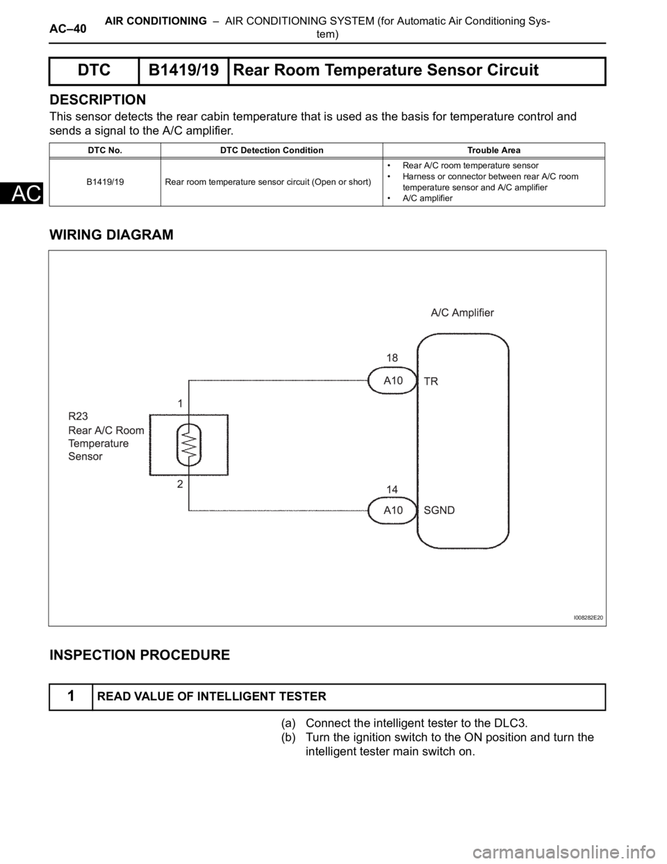
DESCRIPTION
This sensor detects the rear cabin temperature that is used as the basis for temperature control and
sends a signal to the A/C amplifier.
WIRING DIAGRAM
INSPECTION PROCEDURE
(a) Connect the intelligent tester to the DLC3.
(b) Turn the ignition switch to the ON position and turn the
intelligent tester main switch on.
DTC B1419/19 Rear Room Temperature Sensor Circuit
DTC No. DTC Detection Condition Trouble Area
B1419/19 Rear room temperature sensor circuit (Open or short)• Rear A/C room temperature sensor
• Harness or connector between rear A/C room
temperature sensor and A/C amplifier
• A/C amplifier
1READ VALUE OF INTELLIGENT TESTER
I008282E20
Page 2760 of 3000
AIR CONDITIONING – AIR CONDITIONING SYSTEM (for Automatic Air Conditioning Sys-
tem)AC–41
AC
(c) Select the item below in the DATA LIST, and read the
display on the intelligent tester.
DATA LIST / AIR CONDITIONER:
OK:
The display is as specified in the normal condition
column.
Result
B
C
A
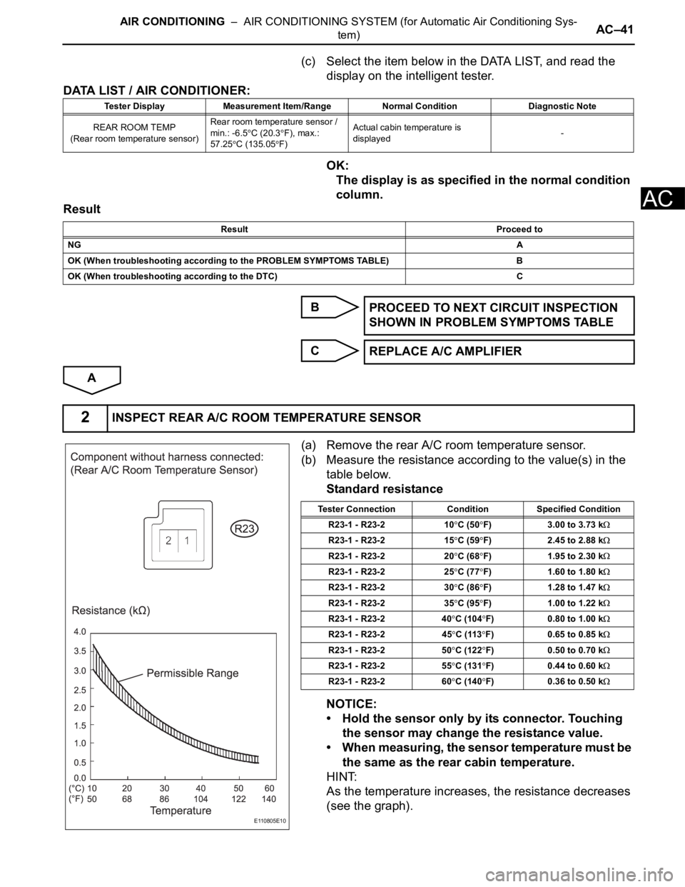
(a) Remove the rear A/C room temperature sensor.
(b) Measure the resistance according to the value(s) in the
table below.
Standard resistance
NOTICE:
• Hold the sensor only by its connector. Touching
the sensor may change the resistance value.
• When measuring, the sensor temperature must be
the same as the rear cabin temperature.
HINT:
As the temperature increases, the resistance decreases
(see the graph).
Tester Display Measurement Item/Range Normal Condition Diagnostic Note
REAR ROOM TEMP
(Rear room temperature sensor)Rear room temperature sensor /
min.: -6.5
C (20.3F), max.:
57.25
C (135.05F)Actual cabin temperature is
displayed-
Result Proceed to
NGA
OK (When troubleshooting according to the PROBLEM SYMPTOMS TABLE) B
OK (When troubleshooting according to the DTC) C
PROCEED TO NEXT CIRCUIT INSPECTION
SHOWN IN PROBLEM SYMPTOMS TABLE
REPLACE A/C AMPLIFIER
2INSPECT REAR A/C ROOM TEMPERATURE SENSOR
E110805E10
Tester Connection Condition Specified Condition
R23-1 - R23-2 10
C (50F) 3.00 to 3.73 k
R23-1 - R23-2 15C (59F) 2.45 to 2.88 k
R23-1 - R23-2 20C (68F) 1.95 to 2.30 k
R23-1 - R23-2 25C (77F) 1.60 to 1.80 k
R23-1 - R23-2 30C (86F) 1.28 to 1.47 k
R23-1 - R23-2 35C (95F) 1.00 to 1.22 k
R23-1 - R23-2 40C (104F) 0.80 to 1.00 k
R23-1 - R23-2 45C (113F) 0.65 to 0.85 k
R23-1 - R23-2 50C (122F) 0.50 to 0.70 k
R23-1 - R23-2 55C (131F) 0.44 to 0.60 k
R23-1 - R23-2 60C (140F) 0.36 to 0.50 k