TOYOTA SIENNA 2007 Service Repair Manual
Manufacturer: TOYOTA, Model Year: 2007, Model line: SIENNA, Model: TOYOTA SIENNA 2007Pages: 3000, PDF Size: 52.26 MB
Page 2761 of 3000
AC–42AIR CONDITIONING – AIR CONDITIONING SYSTEM (for Automatic Air Conditioning Sys-
tem)
AC
NG
OK
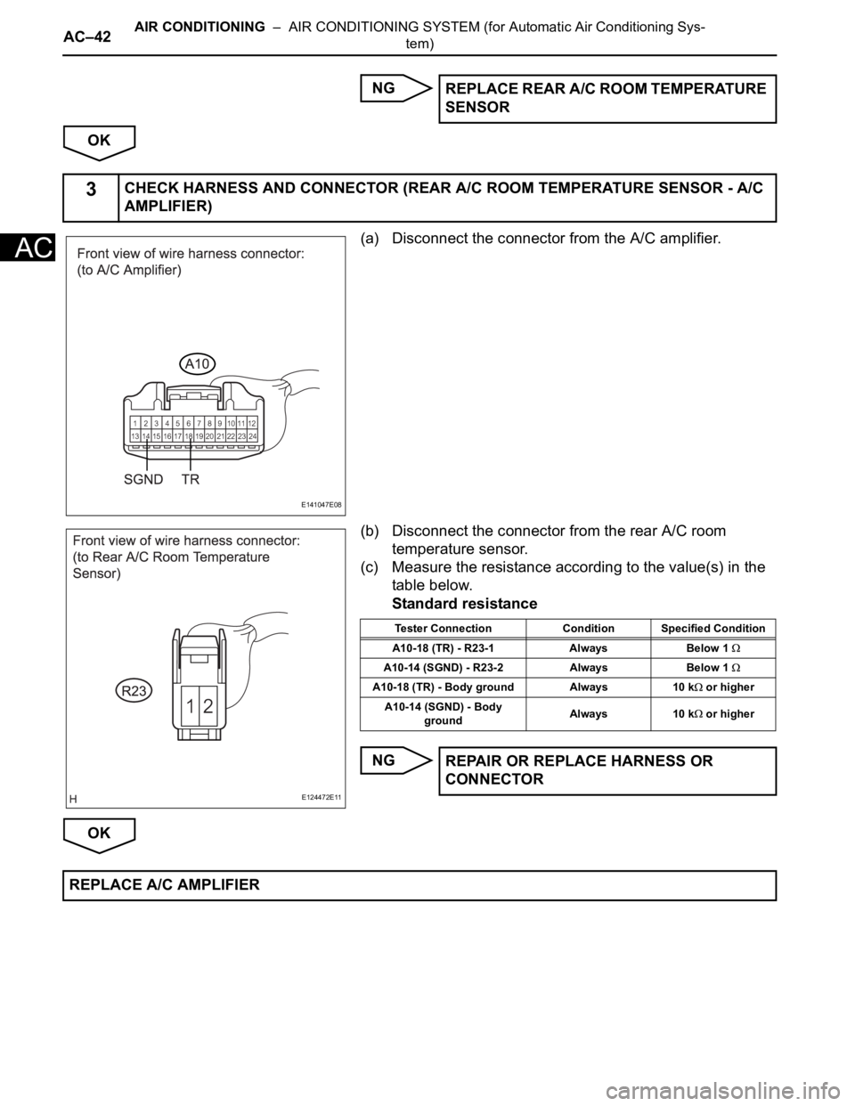
(a) Disconnect the connector from the A/C amplifier.
(b) Disconnect the connector from the rear A/C room
temperature sensor.
(c) Measure the resistance according to the value(s) in the
table below.
Standard resistance
NG
OKREPLACE REAR A/C ROOM TEMPERATURE
SENSOR
3CHECK HARNESS AND CONNECTOR (REAR A/C ROOM TEMPERATURE SENSOR - A/C
AMPLIFIER)
E141047E08
E124472E11
Tester Connection Condition Specified Condition
A10-18 (TR) - R23-1 Always Below 1
A10-14 (SGND) - R23-2 Always Below 1
A10-18 (TR) - Body ground Always 10 k or higher
A10-14 (SGND) - Body
groundAlways 10 k
or higher
REPAIR OR REPLACE HARNESS OR
CONNECTOR
REPLACE A/C AMPLIFIER
Page 2762 of 3000
AC–8AIR CONDITIONING – AIR CONDITIONING SYSTEM (for Automatic Air Conditioning Sys-
tem)
AC
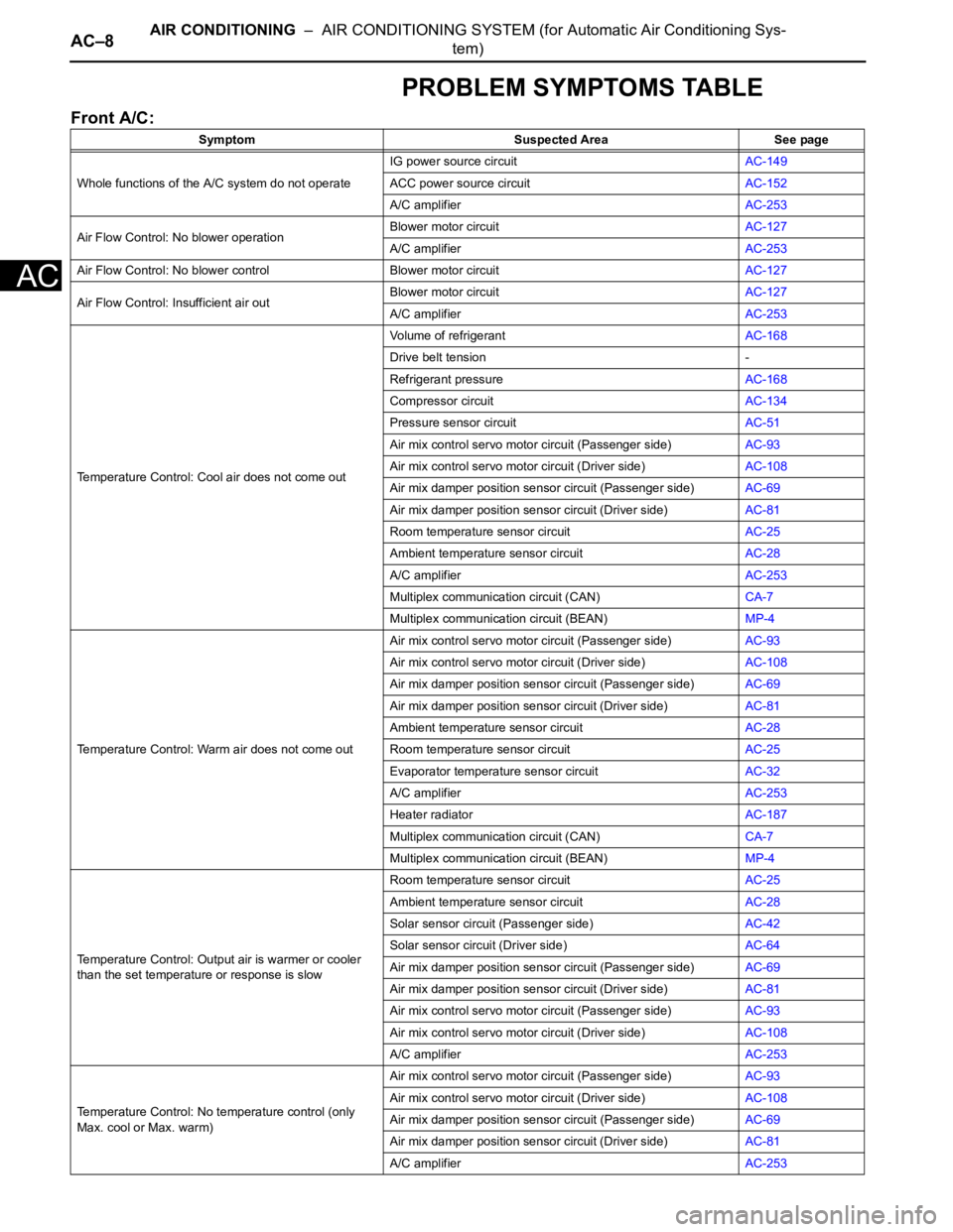
PROBLEM SYMPTOMS TABLE
Front A/C:
Symptom Suspected Area See page
Whole functions of the A/C system do not operateIG power source circuitAC-149
ACC power source circuitAC-152
A/C amplifierAC-253
Air Flow Control: No blower operationBlower motor circuitAC-127
A/C amplifierAC-253
Air Flow Control: No blower control Blower motor circuitAC-127
Air Flow Control: Insufficient air outBlower motor circuitAC-127
A/C amplifierAC-253
Temperature Control: Cool air does not come outVolume of refrigerantAC-168
Drive belt tension -
Refrigerant pressureAC-168
Compressor circuitAC-134
Pressure sensor circuitAC-51
Air mix control servo motor circuit (Passenger side)AC-93
Air mix control servo motor circuit (Driver side)AC-108
Air mix damper position sensor circuit (Passenger side)AC-69
Air mix damper position sensor circuit (Driver side)AC-81
Room temperature sensor circuitAC-25
Ambient temperature sensor circuitAC-28
A/C amplifierAC-253
Multiplex communication circuit (CAN)CA-7
Multiplex communication circuit (BEAN)MP-4
Temperature Control: Warm air does not come outAir mix control servo motor circuit (Passenger side)AC-93
Air mix control servo motor circuit (Driver side)AC-108
Air mix damper position sensor circuit (Passenger side)AC-69
Air mix damper position sensor circuit (Driver side)AC-81
Ambient temperature sensor circuitAC-28
Room temperature sensor circuitAC-25
Evaporator temperature sensor circuitAC-32
A/C amplifierAC-253
Heater radiatorAC-187
Multiplex communication circuit (CAN)CA-7
Multiplex communication circuit (BEAN)MP-4
Temperature Control: Output air is warmer or cooler
than the set temperature or response is slowRoom temperature sensor circuitAC-25
Ambient temperature sensor circuitAC-28
Solar sensor circuit (Passenger side)AC-42
Solar sensor circuit (Driver side)AC-64
Air mix damper position sensor circuit (Passenger side)AC-69
Air mix damper position sensor circuit (Driver side)AC-81
Air mix control servo motor circuit (Passenger side)AC-93
Air mix control servo motor circuit (Driver side)AC-108
A/C amplifierAC-253
Temperature Control: No temperature control (only
Max. cool or Max. warm)Air mix control servo motor circuit (Passenger side)AC-93
Air mix control servo motor circuit (Driver side)AC-108
Air mix damper position sensor circuit (Passenger side)
AC-69
Air mix damper position sensor circuit (Driver side)AC-81
A/C amplifierAC-253
Page 2763 of 3000
AIR CONDITIONING – AIR CONDITIONING SYSTEM (for Automatic Air Conditioning Sys-
tem)AC–9
AC
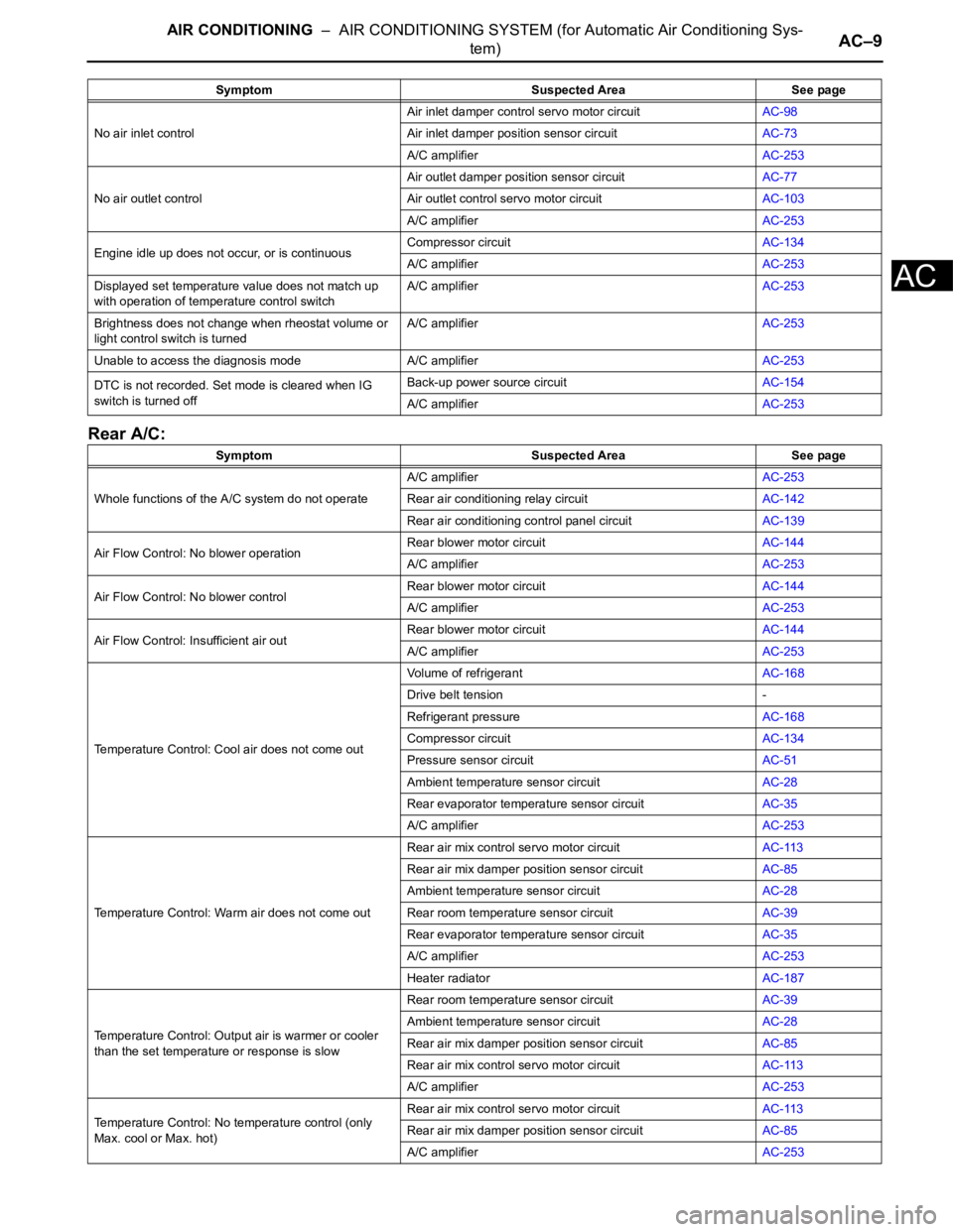
Rear A/C:
No air inlet controlAir inlet damper control servo motor circuitAC-98
Air inlet damper position sensor circuitAC-73
A/C amplifierAC-253
No air outlet controlAir outlet damper position sensor circuitAC-77
Air outlet control servo motor circuitAC-103
A/C amplifierAC-253
Engine idle up does not occur, or is continuousCompressor circuitAC-134
A/C amplifierAC-253
Displayed set temperature value does not match up
with operation of temperature control switchA/C amplifierAC-253
Brightness does not change when rheostat volume or
light control switch is turnedA/C amplifierAC-253
Unable to access the diagnosis mode A/C amplifierAC-253
DTC is not recorded. Set mode is cleared when IG
switch is turned offBack-up power source circuitAC-154
A/C amplifierAC-253
Symptom Suspected Area See page
Whole functions of the A/C system do not operateA/C amplifierAC-253
Rear air conditioning relay circuitAC-142
Rear air conditioning control panel circuitAC-139
Air Flow Control: No blower operationRear blower motor circuitAC-144
A/C amplifierAC-253
Air Flow Control: No blower controlRear blower motor circuitAC-144
A/C amplifierAC-253
Air Flow Control: Insufficient air outRear blower motor circuitAC-144
A/C amplifierAC-253
Temperature Control: Cool air does not come outVolume of refrigerantAC-168
Drive belt tension -
Refrigerant pressureAC-168
Compressor circuitAC-134
Pressure sensor circuitAC-51
Ambient temperature sensor circuitAC-28
Rear evaporator temperature sensor circuitAC-35
A/C amplifierAC-253
Temperature Control: Warm air does not come outRear air mix control servo motor circuitAC-113
Rear air mix damper position sensor circuitAC-85
Ambient temperature sensor circuitAC-28
Rear room temperature sensor circuitAC-39
Rear evaporator temperature sensor circuitAC-35
A/C amplifierAC-253
Heater radiatorAC-187
Temperature Control: Output air is warmer or cooler
than the set temperature or response is slowRear room temperature sensor circuitAC-39
Ambient temperature sensor circuitAC-28
Rear air mix damper position sensor circuitAC-85
Rear air mix control servo motor circuitAC-113
A/C amplifierAC-253
Temperature Control: No temperature control (only
Max. cool or Max. hot)Rear air mix control servo motor circuitAC-113
Rear air mix damper position sensor circuitAC-85
A/C amplifierAC-253 Symptom Suspected Area See page
Page 2764 of 3000

AC–10AIR CONDITIONING – AIR CONDITIONING SYSTEM (for Automatic Air Conditioning Sys-
tem)
AC
No air outlet controlRear air outlet damper position sensor circuitAC-89
Rear air outlet control servo motor circuitAC-118
A/C amplifierAC-253 Symptom Suspected Area See page
Page 2765 of 3000

AC–16AIR CONDITIONING – AIR CONDITIONING SYSTEM (for Automatic Air Conditioning Sys-
tem)
AC
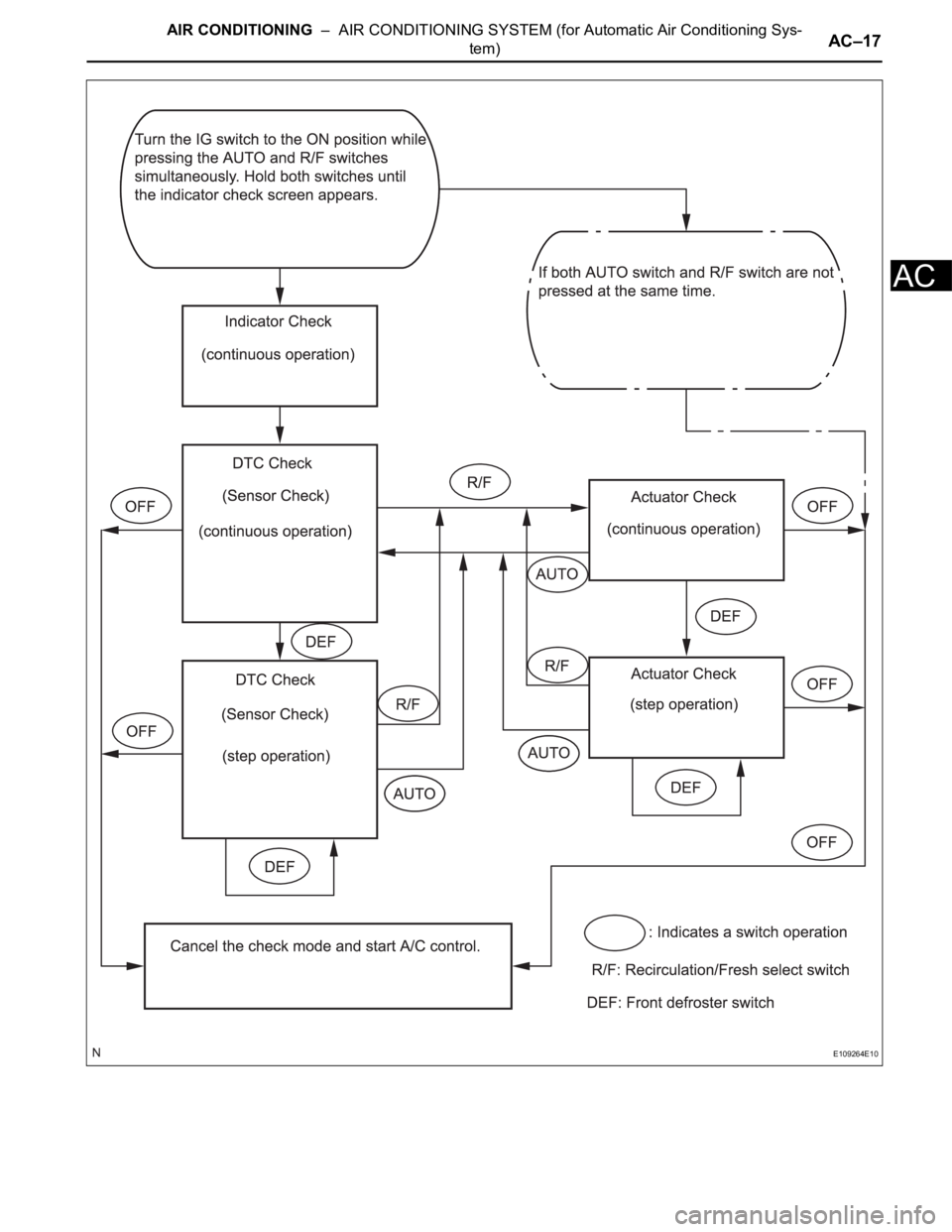
CHECK MODE PROCEDURE
1. LIST OF OPERATION METHODS
By operating each of the A/C control switches as shown
in the diagram below, it is possible to enter the diagnosis
check mode.
Page 2766 of 3000
AIR CONDITIONING – AIR CONDITIONING SYSTEM (for Automatic Air Conditioning Sys-
tem)AC–17
AC
E109264E10
Page 2767 of 3000
AIR CONDITIONING – AIR CONDITIONING SYSTEM (for Automatic Air Conditioning Sys-
tem)AC–21
AC
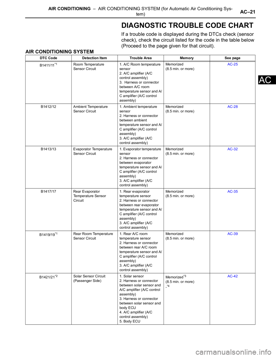
DIAGNOSTIC TROUBLE CODE CHART
If a trouble code is displayed during the DTCs check (sensor
check), check the circuit listed for the code in the table below
(Proceed to the page given for that circuit).
AIR CONDITIONING SYSTEM
DTC Code Detection Item Trouble Area Memory See page
B1411/11
*1Room Temperature
Sensor Circuit1. A/C Room temperature
sensor
2. A/C amplifier (A/C
control assembly)
3. Harness or connector
between A/C room
temperature sensor and A/
C amplifier (A/C control
assembly)Memorized
(8.5 min. or more)AC-25
B1412/12 Ambient Temperature
Sensor Circuit1. Ambient temperature
sensor
2. Harness or connector
between ambient
temperature sensor and A/
C amplifier (A/C control
assembly)
3. A/C amplifier (A/C
control assembly)Memorized
(8.5 min. or more)AC-28
B1413/13 Evaporator Temperature
Sensor Circuit1. Evaporator temperature
sensor
2. Harness or connector
between evaporator
temperature sensor and A/
C amplifier (A/C control
assembly)
3. A/C amplifier (A/C
control assembly)Memorized
(8.5 min. or more)AC-32
B1417/17 Rear Evaporator
Temperature Sensor
Circuit1. Rear evaporator
temperature sensor
2. Harness or connector
between rear evaporator
temperature sensor and A/
C amplifier (A/C control
assembly)
3. A/C amplifier (A/C
control assembly)Memorized
(8.5 min. or more)AC-35
B1419/19
*1Rear Room Temperature
Sensor Circuit1. Rear A/C room
temperature sensor
2. Harness or connector
between rear A/C room
temperature sensor and A/
C amplifier (A/C control
assembly)
3. A/C amplifier (A/C
control assembly)Memorized
(8.5 min. or more)AC-39
B1421/21
*2Solar Sensor Circuit
(Passenger Side)1. Solar sensor
2. Harness or connector
between solar sensor and
A/C amplifier (A/C control
assembly)
3. Harness or connector
between solar sensor and
body ECU
4. A/C amplifier (A/C
control assembly)
5. Body ECUMemorized*3
(8.5 min. or more)
-*4
AC-42
Page 2768 of 3000

AC–22AIR CONDITIONING – AIR CONDITIONING SYSTEM (for Automatic Air Conditioning Sys-
tem)
AC
B1422/22 Compressor Lock Sensor
Circuit1. A/C compressor (A/C
lock sensor)
2. Compressor drive belt
3. Harness or connector
between compressor and
magnetic clutch (A/C lock
sensor)
4. A/C amplifier
5. CAN communication
system
6. Multiplex
communication system
(BEAN)-AC-47
B1423/23 Pressure Sensor Circuit 1. Pressure sensor
2. Harness or connector
between pressure sensor
and A/C amplifier
3. A/C amplifier
4. Expansion valve
(blocked, stuck)
5. Condenser (blocked,
deterioration of cooling
capacity due to dirt)
6. Cooler dryer (moisture
in the refrigerant cycle
cannot be absorbed)
7. Cooling fan system
(condenser cannot be
cooled down)
8. A/C system (leaks,
blocked)-AC-51
B1424/24
*2Solar Sensor Circuit
(Driver Side)1. Solar sensor
2. Harness or connector
between solar sensor and
A/C amplifier (A/C control
assembly)
3. Harness or connector
between solar sensor and
body ECU
4. A/C amplifier (A/C
control assembly)
5. Body ECUMemorized*3
(8.5 min. or more)
-AC-64
B1431/31 Air Mix Damper Position
Sensor Circuit (Passenger
Side)1. Air mix damper position
sensor
2. A/C amplifier (A/C
control assembly)
3. Harness or connector
between air mix damper
position sensor and A/C
amplifier (A/C control
assembly)Memorized
(1 min. or more)AC-69
B1432/32 Air Inlet Damper Position
Sensor Circuit1. Air inlet damper position
sensor (Air inlet control
servo motor)
2. A/C amplifier (A/C
control assembly)
3. Harness or connector
between air inlet damper
position sensor and A/C
amplifier (A/C control
assembly)Memorized
(1 min. or more)AC-73 DTC Code Detection Item Trouble Area Memory See page
Page 2769 of 3000
AIR CONDITIONING – AIR CONDITIONING SYSTEM (for Automatic Air Conditioning Sys-
tem)AC–23
AC
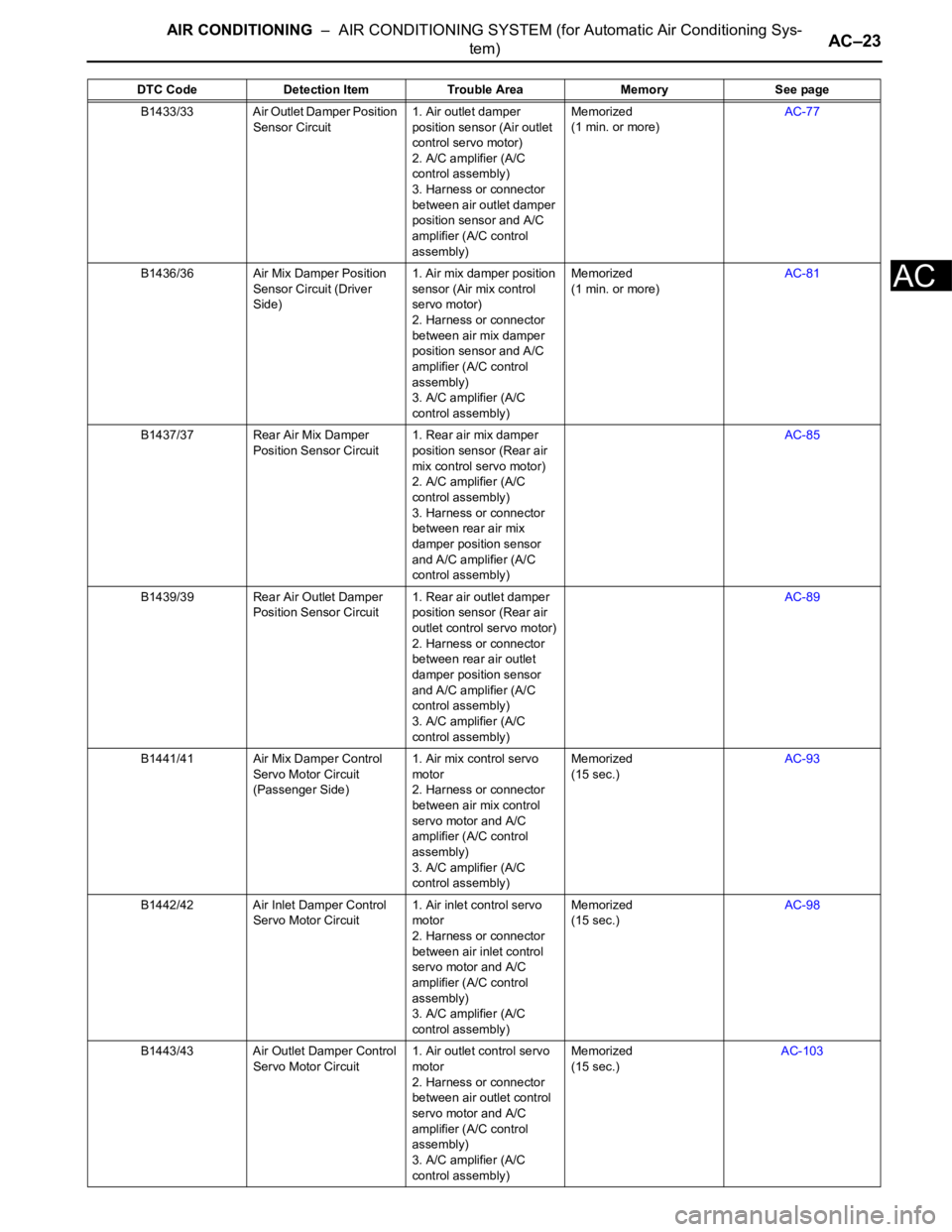
B1433/33 Air Outlet Damper Position
Sensor Circuit1. Air outlet damper
position sensor (Air outlet
control servo motor)
2. A/C amplifier (A/C
control assembly)
3. Harness or connector
between air outlet damper
position sensor and A/C
amplifier (A/C control
assembly)Memorized
(1 min. or more)AC-77
B1436/36 Air Mix Damper Position
Sensor Circuit (Driver
Side)1. Air mix damper position
sensor (Air mix control
servo motor)
2. Harness or connector
between air mix damper
position sensor and A/C
amplifier (A/C control
assembly)
3. A/C amplifier (A/C
control assembly)Memorized
(1 min. or more)AC-81
B1437/37 Rear Air Mix Damper
Position Sensor Circuit1. Rear air mix damper
position sensor (Rear air
mix control servo motor)
2. A/C amplifier (A/C
control assembly)
3. Harness or connector
between rear air mix
damper position sensor
and A/C amplifier (A/C
control assembly)AC-85
B1439/39 Rear Air Outlet Damper
Position Sensor Circuit1. Rear air outlet damper
position sensor (Rear air
outlet control servo motor)
2. Harness or connector
between rear air outlet
damper position sensor
and A/C amplifier (A/C
control assembly)
3. A/C amplifier (A/C
control assembly)AC-89
B1441/41 Air Mix Damper Control
Servo Motor Circuit
(Passenger Side)1. Air mix control servo
motor
2. Harness or connector
between air mix control
servo motor and A/C
amplifier (A/C control
assembly)
3. A/C amplifier (A/C
control assembly)Memorized
(15 sec.)AC-93
B1442/42 Air Inlet Damper Control
Servo Motor Circuit1. Air inlet control servo
motor
2. Harness or connector
between air inlet control
servo motor and A/C
amplifier (A/C control
assembly)
3. A/C amplifier (A/C
control assembly)Memorized
(15 sec.)AC-98
B1443/43 Air Outlet Damper Control
Servo Motor Circuit1. Air outlet control servo
motor
2. Harness or connector
between air outlet control
servo motor and A/C
amplifier (A/C control
assembly)
3. A/C amplifier (A/C
control assembly)Memorized
(15 sec.)AC-103 DTC Code Detection Item Trouble Area Memory See page
Page 2770 of 3000
AC–24AIR CONDITIONING – AIR CONDITIONING SYSTEM (for Automatic Air Conditioning Sys-
tem)
AC
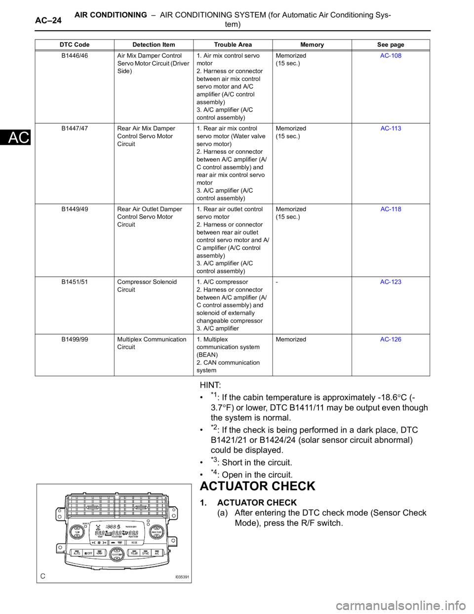
HINT:
•
*1: If the cabin temperature is approximately -18.6C (-
3.7
F) or lower, DTC B1411/11 may be output even though
the system is normal.
•
*2: If the check is being performed in a dark place, DTC
B1421/21 or B1424/24 (solar sensor circuit abnormal)
could be displayed.
•
*3: Short in the circuit.
•
*4: Open in the circuit.
ACTUATOR CHECK
1. ACTUATOR CHECK
(a) After entering the DTC check mode (Sensor Check
Mode), press the R/F switch.
B1446/46 Air Mix Damper Control
Servo Motor Circuit (Driver
Side)1. Air mix control servo
motor
2. Harness or connector
between air mix control
servo motor and A/C
amplifier (A/C control
assembly)
3. A/C amplifier (A/C
control assembly)Memorized
(15 sec.)AC-108
B1447/47 Rear Air Mix Damper
Control Servo Motor
Circuit1. Rear air mix control
servo motor (Water valve
servo motor)
2. Harness or connector
between A/C amplifier (A/
C control assembly) and
rear air mix control servo
motor
3. A/C amplifier (A/C
control assembly)Memorized
(15 sec.)AC-113
B1449/49 Rear Air Outlet Damper
Control Servo Motor
Circuit1. Rear air outlet control
servo motor
2. Harness or connector
between rear air outlet
control servo motor and A/
C amplifier (A/C control
assembly)
3. A/C amplifier (A/C
control assembly)Memorized
(15 sec.)AC-118
B1451/51 Compressor Solenoid
Circuit1. A/C compressor
2. Harness or connector
between A/C amplifier (A/
C control assembly) and
solenoid of externally
changeable compressor
3. A/C amplifier-AC-123
B1499/99 Multiplex Communication
Circuit1. Multiplex
communication system
(BEAN)
2. CAN communication
systemMemorizedAC-126 DTC Code Detection Item Trouble Area Memory See page
I035391