TOYOTA SIENNA 2007 Service Repair Manual
Manufacturer: TOYOTA, Model Year: 2007, Model line: SIENNA, Model: TOYOTA SIENNA 2007Pages: 3000, PDF Size: 52.26 MB
Page 911 of 3000
EM–1062GR-FE ENGINE MECHANICAL – ENGINE UNIT
EM
(h) Check for smooth rotation.
(1) Turn the camshaft timing exhaust gear within
its movable range (18.5
) 2 or 3 times, but do
not turn it to the most advanced position. Make
sure that the gear turns smoothly.
NOTICE:
When the air pressure is released from the
advance side path and then from the retard
side path, the gear automatically returns to
the most advanced position due to the
advance assist spring operation and locks.
Gradually release the air pressure from the
retard side path before performing the
smooth rotation check.
(i) Check the lock at the most advanced position.
(1) Make sure that the camshaft timing exhaust
gear is locked at the most advanced position.
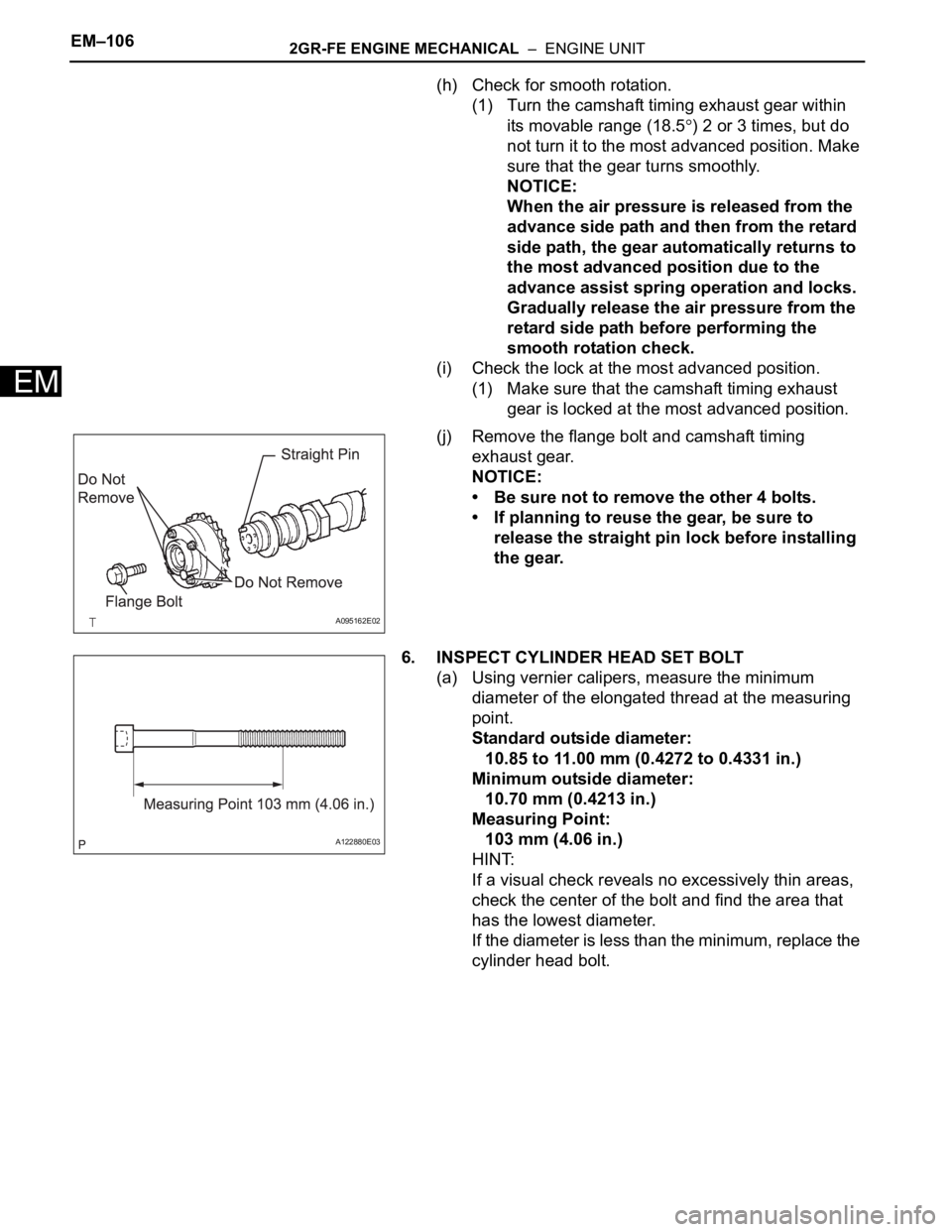
(j) Remove the flange bolt and camshaft timing
exhaust gear.
NOTICE:
• Be sure not to remove the other 4 bolts.
• If planning to reuse the gear, be sure to
release the straight pin lock before installing
the gear.
6. INSPECT CYLINDER HEAD SET BOLT
(a) Using vernier calipers, measure the minimum
diameter of the elongated thread at the measuring
point.
Standard outside diameter:
10.85 to 11.00 mm (0.4272 to 0.4331 in.)
Minimum outside diameter:
10.70 mm (0.4213 in.)
Measuring Point:
103 mm (4.06 in.)
HINT:
If a visual check reveals no excessively thin areas,
check the center of the bolt and find the area that
has the lowest diameter.
If the diameter is less than the minimum, replace the
cylinder head bolt.
A095162E02
A122880E03
Page 912 of 3000
2GR-FE ENGINE MECHANICAL – ENGINE UNITEM–107
EM
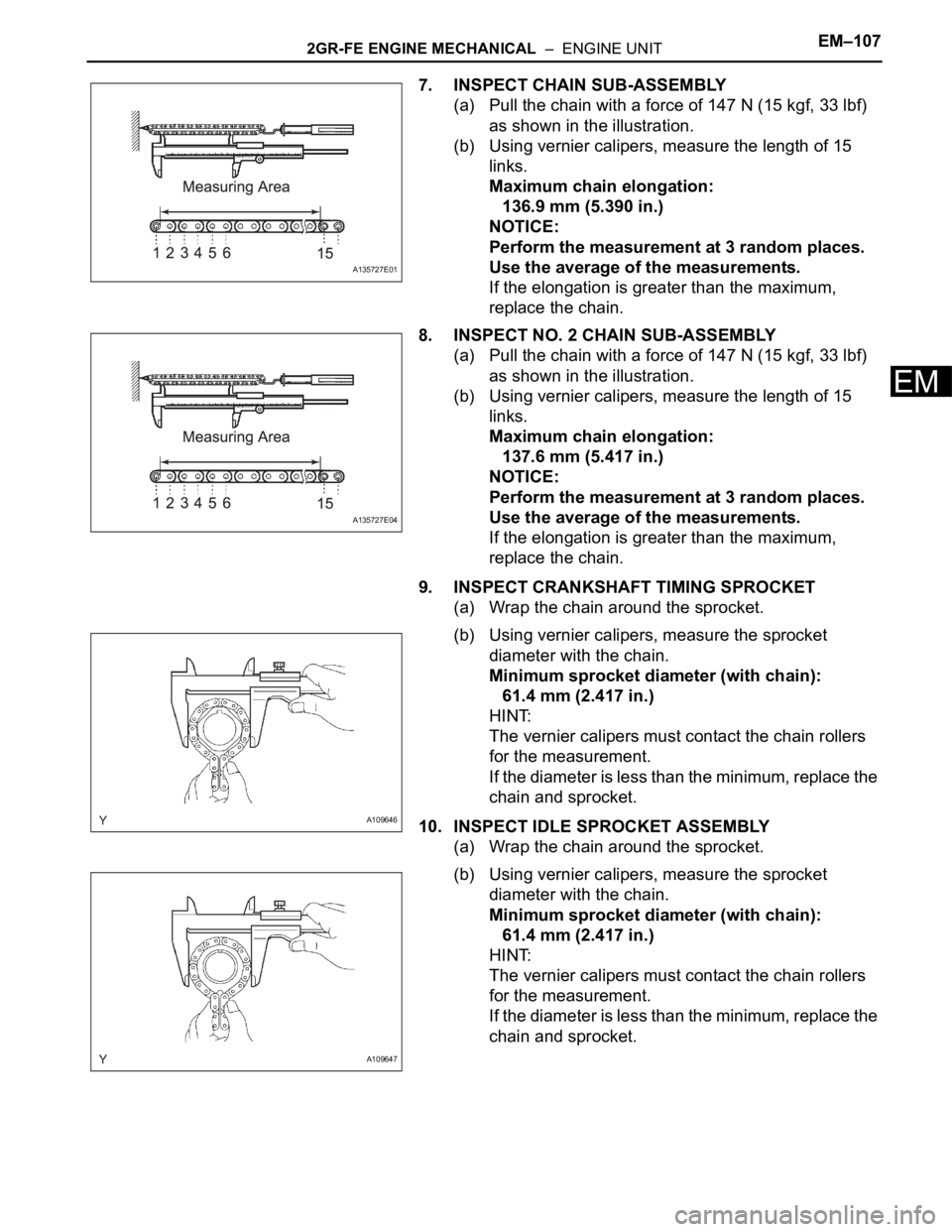
7. INSPECT CHAIN SUB-ASSEMBLY
(a) Pull the chain with a force of 147 N (15 kgf, 33 lbf)
as shown in the illustration.
(b) Using vernier calipers, measure the length of 15
links.
Maximum chain elongation:
136.9 mm (5.390 in.)
NOTICE:
Perform the measurement at 3 random places.
Use the average of the measurements.
If the elongation is greater than the maximum,
replace the chain.
8. INSPECT NO. 2 CHAIN SUB-ASSEMBLY
(a) Pull the chain with a force of 147 N (15 kgf, 33 lbf)
as shown in the illustration.
(b) Using vernier calipers, measure the length of 15
links.
Maximum chain elongation:
137.6 mm (5.417 in.)
NOTICE:
Perform the measurement at 3 random places.
Use the average of the measurements.
If the elongation is greater than the maximum,
replace the chain.
9. INSPECT CRANKSHAFT TIMING SPROCKET
(a) Wrap the chain around the sprocket.
(b) Using vernier calipers, measure the sprocket
diameter with the chain.
Minimum sprocket diameter (with chain):
61.4 mm (2.417 in.)
HINT:
The vernier calipers must contact the chain rollers
for the measurement.
If the diameter is less than the minimum, replace the
chain and sprocket.
10. INSPECT IDLE SPROCKET ASSEMBLY
(a) Wrap the chain around the sprocket.
(b) Using vernier calipers, measure the sprocket
diameter with the chain.
Minimum sprocket diameter (with chain):
61.4 mm (2.417 in.)
HINT:
The vernier calipers must contact the chain rollers
for the measurement.
If the diameter is less than the minimum, replace the
chain and sprocket.
A135727E01
A135727E04
A109646
A109647
Page 913 of 3000
EM–1082GR-FE ENGINE MECHANICAL – ENGINE UNIT
EM
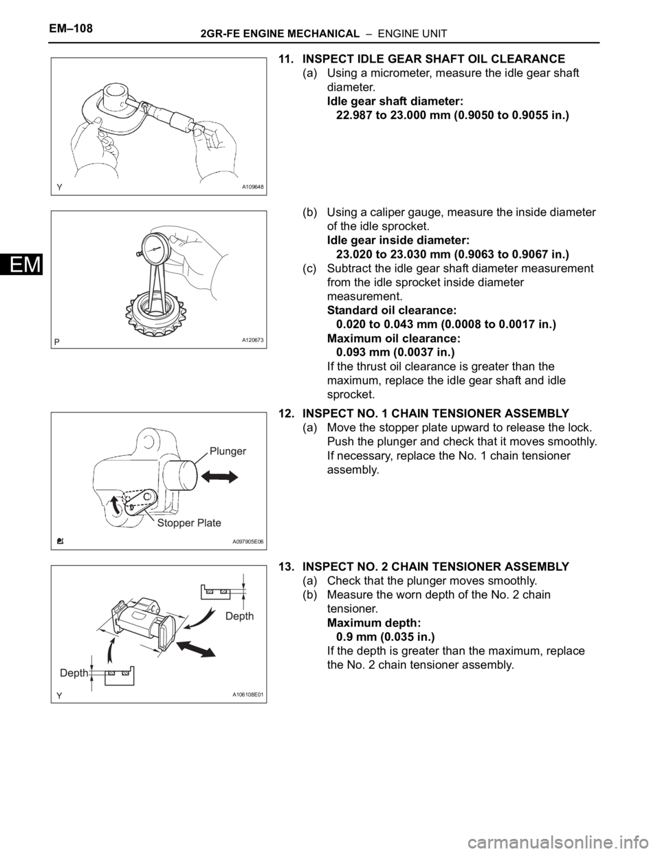
11. INSPECT IDLE GEAR SHAFT OIL CLEARANCE
(a) Using a micrometer, measure the idle gear shaft
diameter.
Idle gear shaft diameter:
22.987 to 23.000 mm (0.9050 to 0.9055 in.)
(b) Using a caliper gauge, measure the inside diameter
of the idle sprocket.
Idle gear inside diameter:
23.020 to 23.030 mm (0.9063 to 0.9067 in.)
(c) Subtract the idle gear shaft diameter measurement
from the idle sprocket inside diameter
measurement.
Standard oil clearance:
0.020 to 0.043 mm (0.0008 to 0.0017 in.)
Maximum oil clearance:
0.093 mm (0.0037 in.)
If the thrust oil clearance is greater than the
maximum, replace the idle gear shaft and idle
sprocket.
12. INSPECT NO. 1 CHAIN TENSIONER ASSEMBLY
(a) Move the stopper plate upward to release the lock.
Push the plunger and check that it moves smoothly.
If necessary, replace the No. 1 chain tensioner
assembly.
13. INSPECT NO. 2 CHAIN TENSIONER ASSEMBLY
(a) Check that the plunger moves smoothly.
(b) Measure the worn depth of the No. 2 chain
tensioner.
Maximum depth:
0.9 mm (0.035 in.)
If the depth is greater than the maximum, replace
the No. 2 chain tensioner assembly.
A109648
A120673
A097905E06
A106108E01
Page 914 of 3000
2GR-FE ENGINE MECHANICAL – ENGINE UNITEM–109
EM
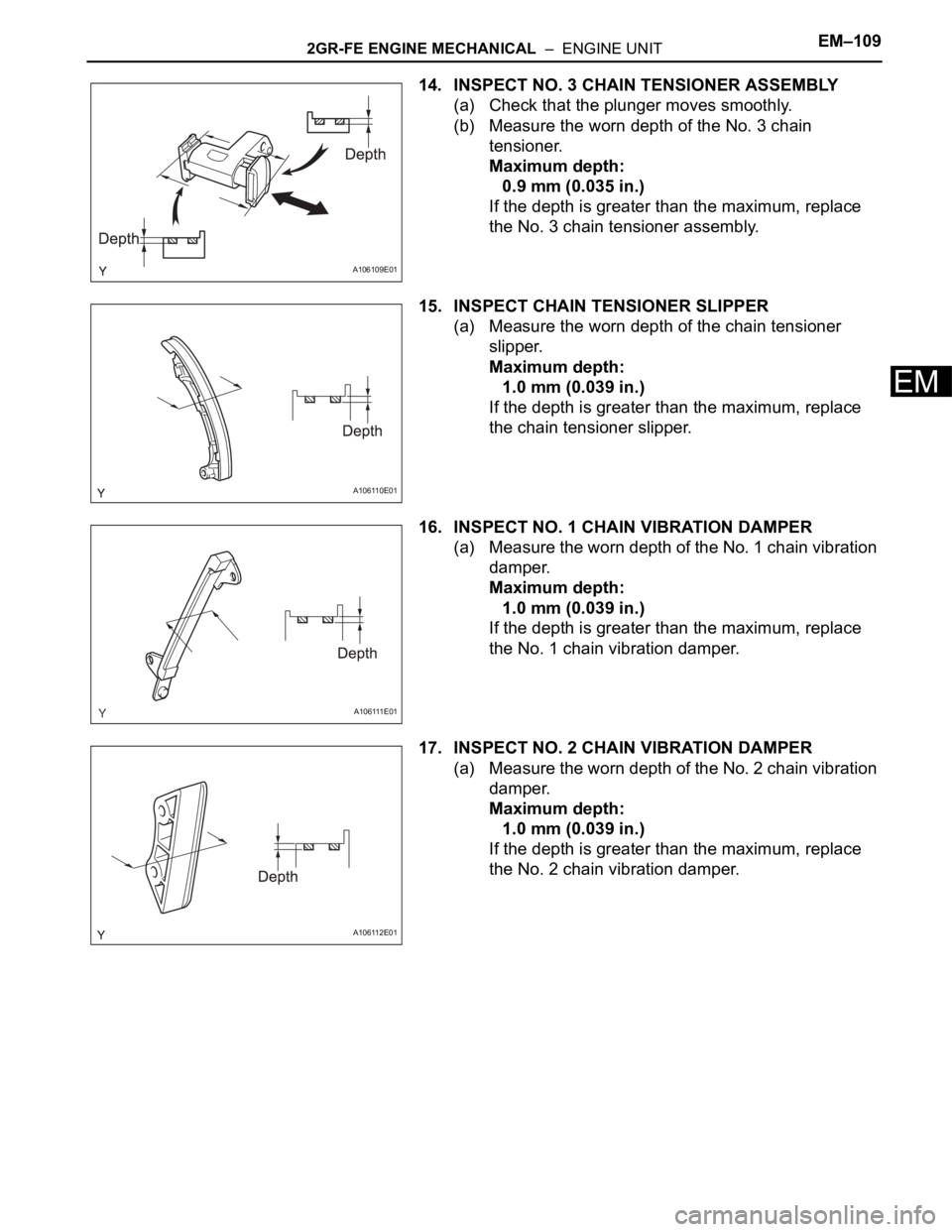
14. INSPECT NO. 3 CHAIN TENSIONER ASSEMBLY
(a) Check that the plunger moves smoothly.
(b) Measure the worn depth of the No. 3 chain
tensioner.
Maximum depth:
0.9 mm (0.035 in.)
If the depth is greater than the maximum, replace
the No. 3 chain tensioner assembly.
15. INSPECT CHAIN TENSIONER SLIPPER
(a) Measure the worn depth of the chain tensioner
slipper.
Maximum depth:
1.0 mm (0.039 in.)
If the depth is greater than the maximum, replace
the chain tensioner slipper.
16. INSPECT NO. 1 CHAIN VIBRATION DAMPER
(a) Measure the worn depth of the No. 1 chain vibration
damper.
Maximum depth:
1.0 mm (0.039 in.)
If the depth is greater than the maximum, replace
the No. 1 chain vibration damper.
17. INSPECT NO. 2 CHAIN VIBRATION DAMPER
(a) Measure the worn depth of the No. 2 chain vibration
damper.
Maximum depth:
1.0 mm (0.039 in.)
If the depth is greater than the maximum, replace
the No. 2 chain vibration damper.
A106109E01
A106110E01
A106111E01
A106112E01
Page 915 of 3000
EM–1102GR-FE ENGINE MECHANICAL – ENGINE UNIT
EM
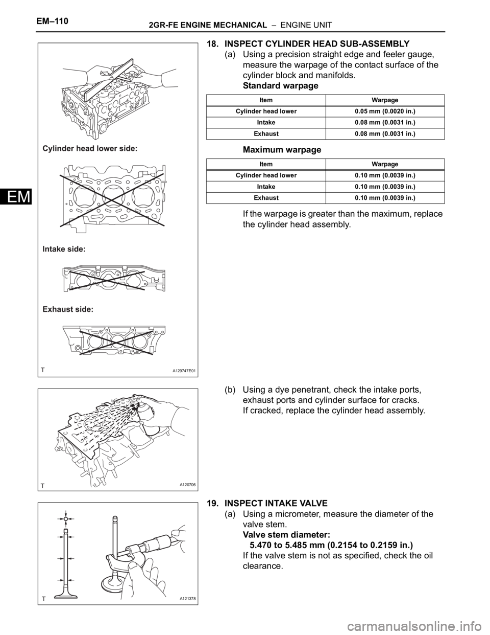
18. INSPECT CYLINDER HEAD SUB-ASSEMBLY
(a) Using a precision straight edge and feeler gauge,
measure the warpage of the contact surface of the
cylinder block and manifolds.
Standard warpage
Maximum warpage
If the warpage is greater than the maximum, replace
the cylinder head assembly.
(b) Using a dye penetrant, check the intake ports,
exhaust ports and cylinder surface for cracks.
If cracked, replace the cylinder head assembly.
19. INSPECT INTAKE VALVE
(a) Using a micrometer, measure the diameter of the
valve stem.
Valve stem diameter:
5.470 to 5.485 mm (0.2154 to 0.2159 in.)
If the valve stem is not as specified, check the oil
clearance.
A129747E01
Item Warpage
Cylinder head lower 0.05 mm (0.0020 in.)
Intake 0.08 mm (0.0031 in.)
Exhaust 0.08 mm (0.0031 in.)
Item Warpage
Cylinder head lower 0.10 mm (0.0039 in.)
Intake 0.10 mm (0.0039 in.)
Exhaust 0.10 mm (0.0039 in.)
A120706
A121378
Page 916 of 3000
2GR-FE ENGINE MECHANICAL – ENGINE UNITEM–111
EM
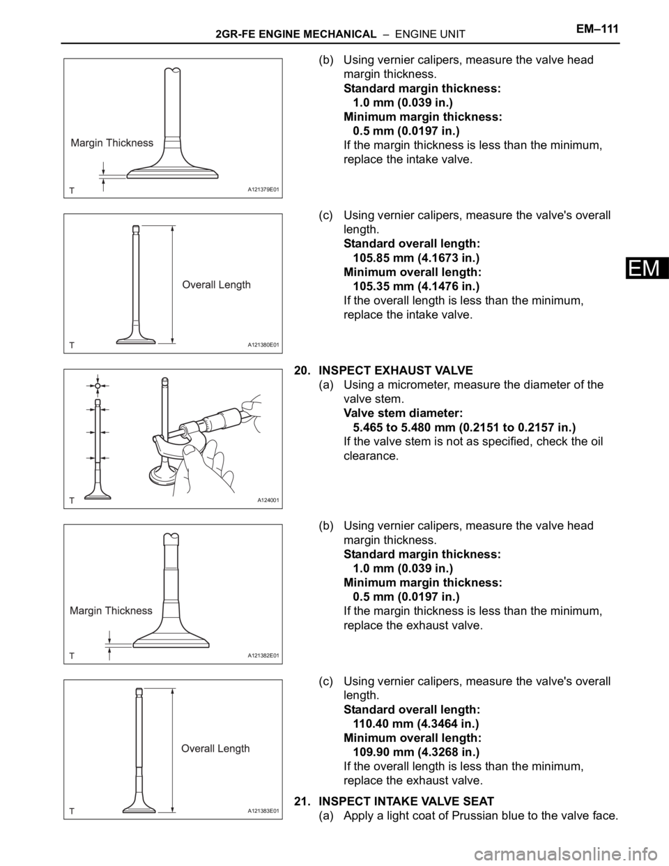
(b) Using vernier calipers, measure the valve head
margin thickness.
Standard margin thickness:
1.0 mm (0.039 in.)
Minimum margin thickness:
0.5 mm (0.0197 in.)
If the margin thickness is less than the minimum,
replace the intake valve.
(c) Using vernier calipers, measure the valve's overall
length.
Standard overall length:
105.85 mm (4.1673 in.)
Minimum overall length:
105.35 mm (4.1476 in.)
If the overall length is less than the minimum,
replace the intake valve.
20. INSPECT EXHAUST VALVE
(a) Using a micrometer, measure the diameter of the
valve stem.
Valve stem diameter:
5.465 to 5.480 mm (0.2151 to 0.2157 in.)
If the valve stem is not as specified, check the oil
clearance.
(b) Using vernier calipers, measure the valve head
margin thickness.
Standard margin thickness:
1.0 mm (0.039 in.)
Minimum margin thickness:
0.5 mm (0.0197 in.)
If the margin thickness is less than the minimum,
replace the exhaust valve.
(c) Using vernier calipers, measure the valve's overall
length.
Standard overall length:
110.40 mm (4.3464 in.)
Minimum overall length:
109.90 mm (4.3268 in.)
If the overall length is less than the minimum,
replace the exhaust valve.
21. INSPECT INTAKE VALVE SEAT
(a) Apply a light coat of Prussian blue to the valve face.
A121379E01
A121380E01
A124001
A121382E01
A121383E01
Page 917 of 3000
EM–1122GR-FE ENGINE MECHANICAL – ENGINE UNIT
EM
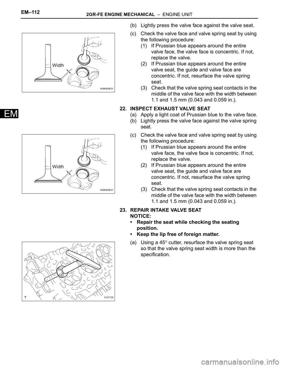
(b) Lightly press the valve face against the valve seat.
(c) Check the valve face and valve spring seat by using
the following procedure:
(1) If Prussian blue appears around the entire
valve face, the valve face is concentric. If not,
replace the valve.
(2) If Prussian blue appears around the entire
valve seat, the guide and valve face are
concentric. If not, resurface the valve spring
seat.
(3) Check that the valve spring seat contacts in the
middle of the valve face with the width between
1.1 and 1.5 mm (0.043 and 0.059 in.).
22. INSPECT EXHAUST VALVE SEAT
(a) Apply a light coat of Prussian blue to the valve face.
(b) Lightly press the valve face against the valve spring
seat.
(c) Check the valve face and valve spring seat by using
the following procedure:
(1) If Prussian blue appears around the entire
valve face, the valve face is concentric. If not,
replace the valve.
(2) If Prussian blue appears around the entire
valve seat, the guide and valve face are
concentric. If not, resurface the valve spring
seat.
(3) Check that the valve spring seat contacts in the
middle of the valve face with the width between
1.1 and 1.5 mm (0.043 and 0.059 in.).
23. REPAIR INTAKE VALVE SEAT
NOTICE:
• Repair the seat while checking the seating
position.
• Keep the lip free of foreign matter.
(a) Using a 45
cutter, resurface the valve spring seat
so that the valve spring seat width is more than the
specification.
A094929E01
A094929E01
A127139
Page 918 of 3000
2GR-FE ENGINE MECHANICAL – ENGINE UNITEM–113
EM
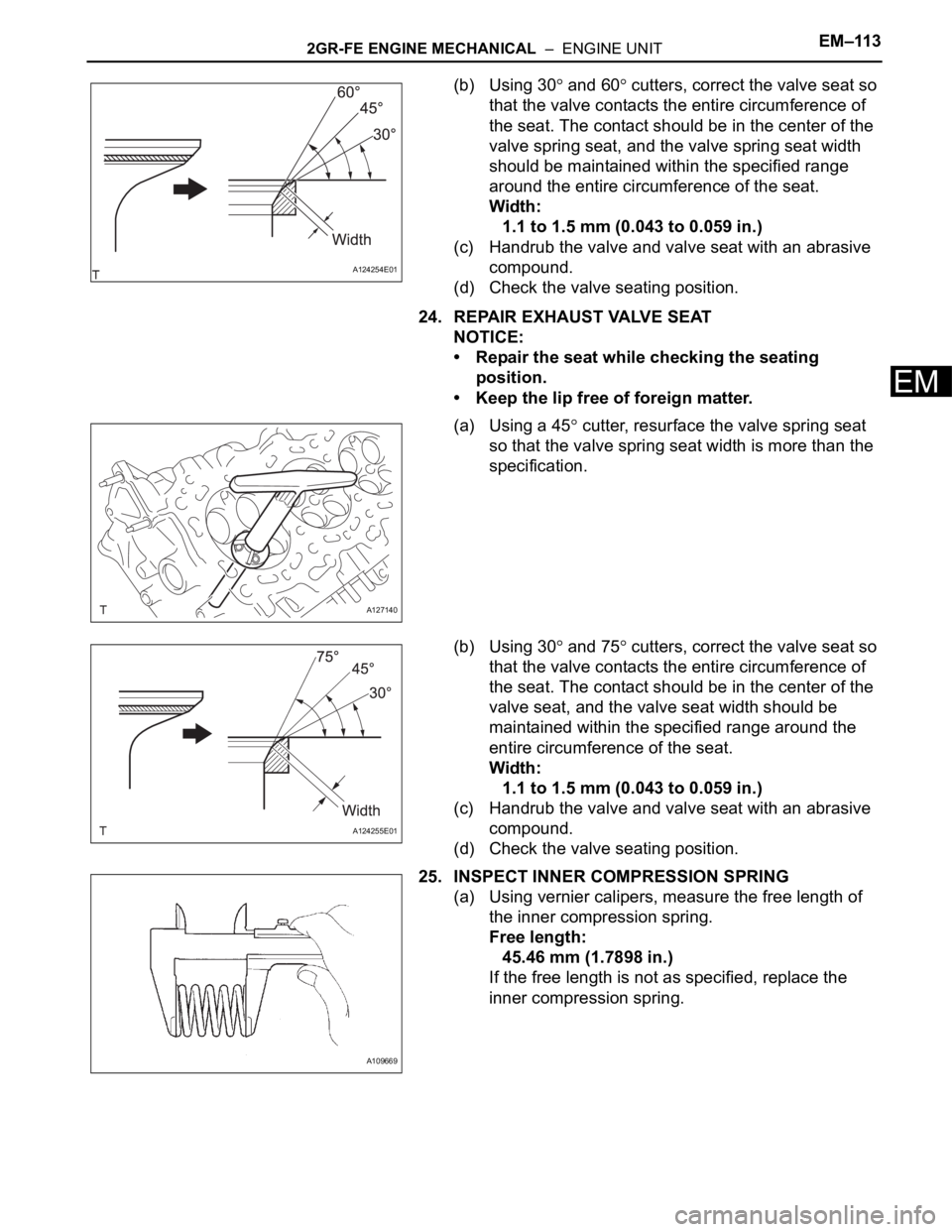
(b) Using 30 and 60 cutters, correct the valve seat so
that the valve contacts the entire circumference of
the seat. The contact should be in the center of the
valve spring seat, and the valve spring seat width
should be maintained within the specified range
around the entire circumference of the seat.
Width:
1.1 to 1.5 mm (0.043 to 0.059 in.)
(c) Handrub the valve and valve seat with an abrasive
compound.
(d) Check the valve seating position.
24. REPAIR EXHAUST VALVE SEAT
NOTICE:
• Repair the seat while checking the seating
position.
• Keep the lip free of foreign matter.
(a) Using a 45
cutter, resurface the valve spring seat
so that the valve spring seat width is more than the
specification.
(b) Using 30
and 75 cutters, correct the valve seat so
that the valve contacts the entire circumference of
the seat. The contact should be in the center of the
valve seat, and the valve seat width should be
maintained within the specified range around the
entire circumference of the seat.
Width:
1.1 to 1.5 mm (0.043 to 0.059 in.)
(c) Handrub the valve and valve seat with an abrasive
compound.
(d) Check the valve seating position.
25. INSPECT INNER COMPRESSION SPRING
(a) Using vernier calipers, measure the free length of
the inner compression spring.
Free length:
45.46 mm (1.7898 in.)
If the free length is not as specified, replace the
inner compression spring.
A124254E01
A127140
A124255E01
A109669
Page 919 of 3000
EM–1142GR-FE ENGINE MECHANICAL – ENGINE UNIT
EM
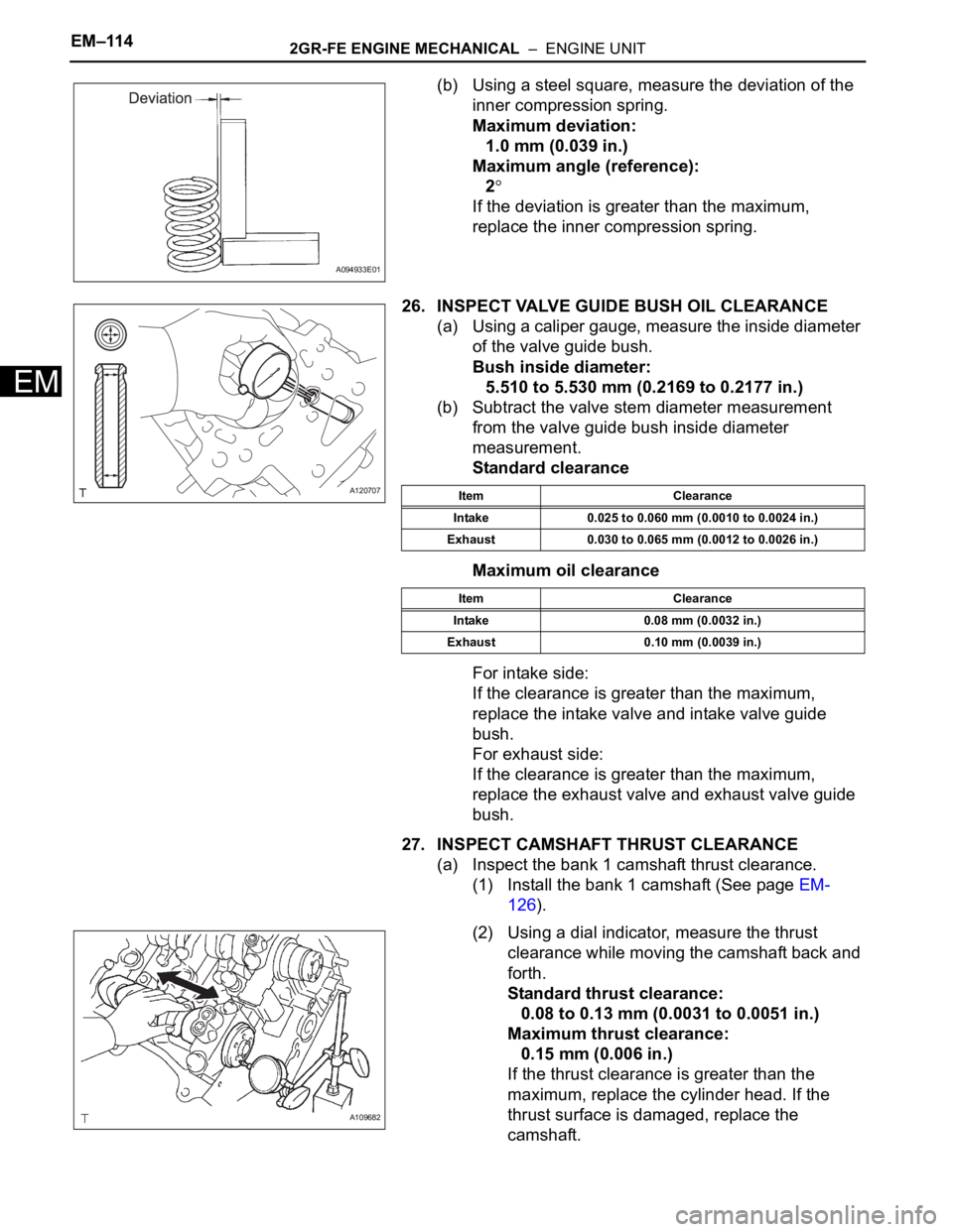
(b) Using a steel square, measure the deviation of the
inner compression spring.
Maximum deviation:
1.0 mm (0.039 in.)
Maximum angle (reference):
2
If the deviation is greater than the maximum,
replace the inner compression spring.
26. INSPECT VALVE GUIDE BUSH OIL CLEARANCE
(a) Using a caliper gauge, measure the inside diameter
of the valve guide bush.
Bush inside diameter:
5.510 to 5.530 mm (0.2169 to 0.2177 in.)
(b) Subtract the valve stem diameter measurement
from the valve guide bush inside diameter
measurement.
Standard clearance
Maximum oil clearance
For intake side:
If the clearance is greater than the maximum,
replace the intake valve and intake valve guide
bush.
For exhaust side:
If the clearance is greater than the maximum,
replace the exhaust valve and exhaust valve guide
bush.
27. INSPECT CAMSHAFT THRUST CLEARANCE
(a) Inspect the bank 1 camshaft thrust clearance.
(1) Install the bank 1 camshaft (See page EM-
126).
(2) Using a dial indicator, measure the thrust
clearance while moving the camshaft back and
forth.
Standard thrust clearance:
0.08 to 0.13 mm (0.0031 to 0.0051 in.)
Maximum thrust clearance:
0.15 mm (0.006 in.)
If the thrust clearance is greater than the
maximum, replace the cylinder head. If the
thrust surface is damaged, replace the
camshaft.
A094933E01
A120707Item Clearance
Intake 0.025 to 0.060 mm (0.0010 to 0.0024 in.)
Exhaust 0.030 to 0.065 mm (0.0012 to 0.0026 in.)
Item Clearance
Intake 0.08 mm (0.0032 in.)
Exhaust 0.10 mm (0.0039 in.)
A109682
Page 920 of 3000
2GR-FE ENGINE MECHANICAL – ENGINE UNITEM–115
EM
(b) Inspect the bank 2 camshaft thrust clearance.
(1) Install the bank 2 camshaft (See page EM-
126).
(2) Using a dial indicator, measure the thrust
clearance while moving the camshaft back and
forth.
Standard thrust clearance:
0.08 to 0.13 mm (0.0031 to 0.0051 in.)
Maximum thrust clearance:
0.15 mm (0.006 in.)
If the thrust clearance is greater than the
maximum, replace the cylinder head. If the
thrust surface is damaged, replace the
camshaft.
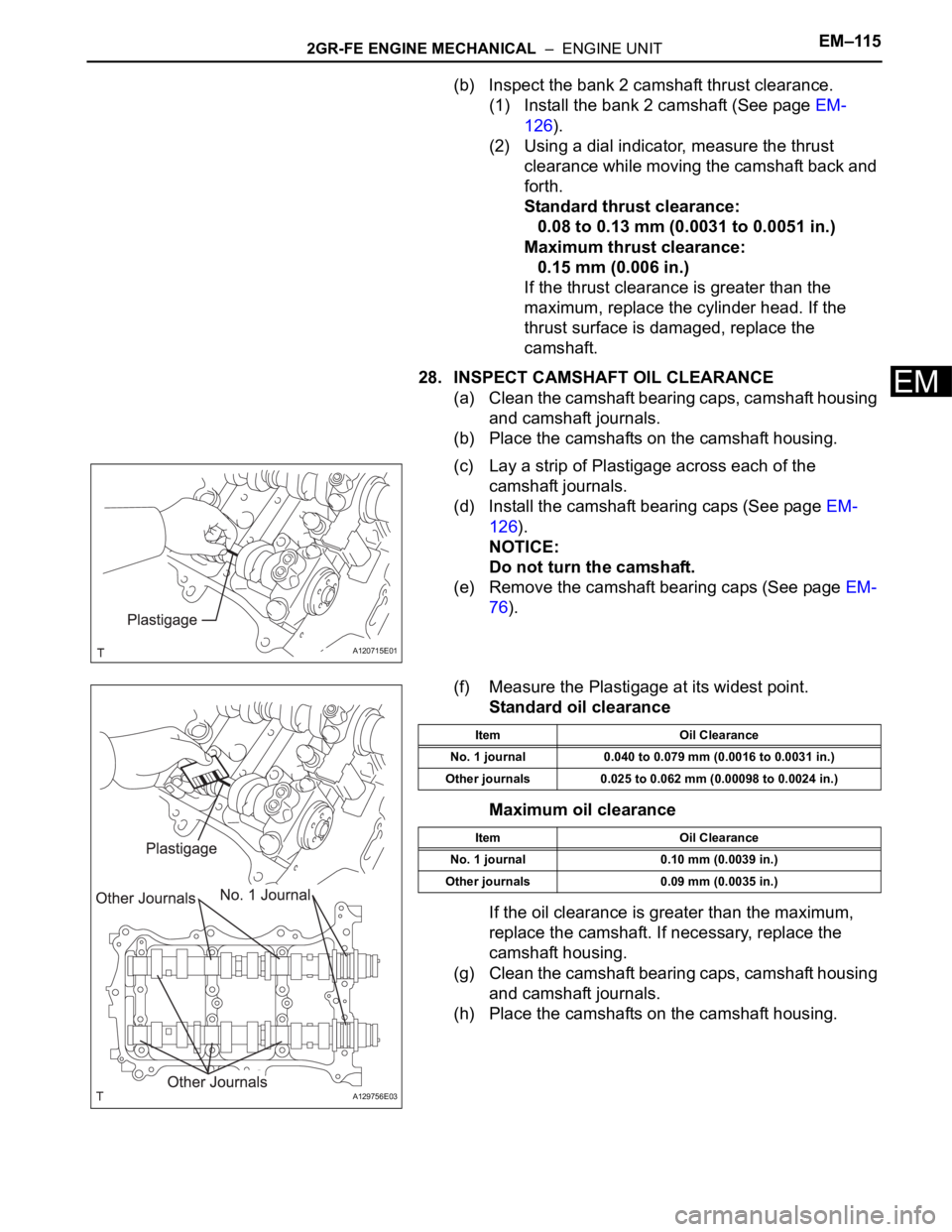
28. INSPECT CAMSHAFT OIL CLEARANCE
(a) Clean the camshaft bearing caps, camshaft housing
and camshaft journals.
(b) Place the camshafts on the camshaft housing.
(c) Lay a strip of Plastigage across each of the
camshaft journals.
(d) Install the camshaft bearing caps (See page EM-
126).
NOTICE:
Do not turn the camshaft.
(e) Remove the camshaft bearing caps (See page EM-
76).
(f) Measure the Plastigage at its widest point.
Standard oil clearance
Maximum oil clearance
If the oil clearance is greater than the maximum,
replace the camshaft. If necessary, replace the
camshaft housing.
(g) Clean the camshaft bearing caps, camshaft housing
and camshaft journals.
(h) Place the camshafts on the camshaft housing.
A120715E01
A129756E03
Item Oil Clearance
No. 1 journal 0.040 to 0.079 mm (0.0016 to 0.0031 in.)
Other journals 0.025 to 0.062 mm (0.00098 to 0.0024 in.)
Item Oil Clearance
No. 1 journal 0.10 mm (0.0039 in.)
Other journals 0.09 mm (0.0035 in.)