TOYOTA SUPRA 1986 Service Repair Manual
SUPRA 1986
TOYOTA
TOYOTA
https://www.carmanualsonline.info/img/14/57467/w960_57467-0.png
TOYOTA SUPRA 1986 Service Repair Manual
Trending: roof rack, fuse diagram, horn, manual transmission, key battery, reset, checking oil
Page 231 of 878
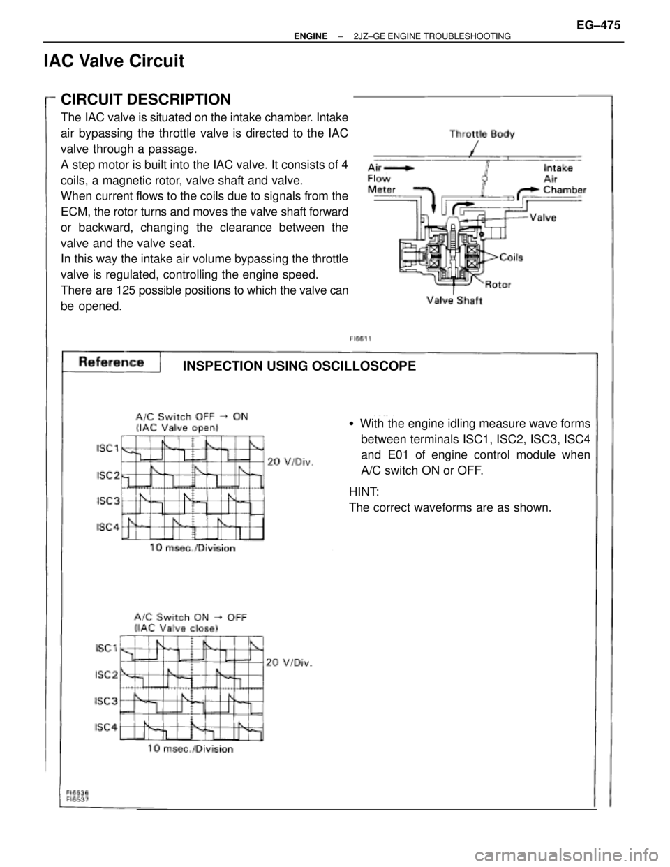
CIRCUIT DESCRIPTION
The IAC valve is situated on the intake chamber. Intake
air bypassing the throttle valve is directed to the IAC
valve through a passage.
A step motor is built into the IAC valve. It consists of 4
coils, a magnetic rotor, valve shaft and valve.
When current flows to the coils due to signals from the
ECM, the rotor turns and moves the valve shaft forward
or backward, changing the clearance between the
valve and the valve seat.
In this way the intake air volume bypassing the throttle
valve is regulated, controlling the engine speed.
There are 125 possible positions to which the valve can
be opened.
�With the engine idling measure wave forms
between terminals ISC1, ISC2, ISC3, ISC4
and E01 of engine control module when
A/C switch ON or OFF.
HINT:
The correct waveforms are as shown.
INSPECTION USING OSCILLOSCOPE
IAC Valve Circuit
± ENGINE2JZ±GE ENGINE TROUBLESHOOTINGEG±475
Page 232 of 878
EG±476± ENGINE2JZ±GE ENGINE TROUBLESHOOTING
Page 233 of 878
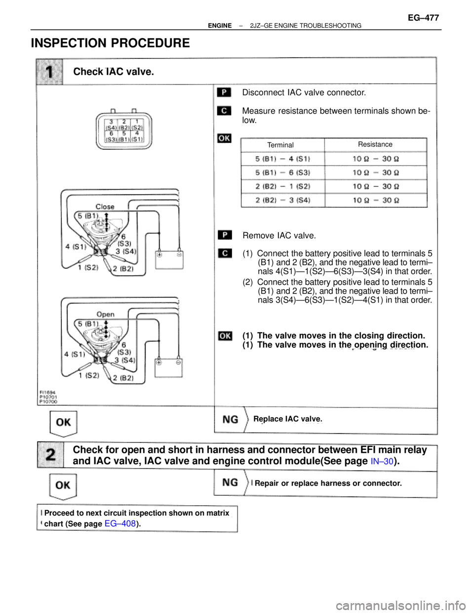
INSPECTION PROCEDURE
Check IAC valve.
Disconnect IAC valve connector.
Measure resistance between terminals shown be-
low.
Replace IAC valve.
Remove IAC valve.
(1) Connect the battery positive lead to terminals 5
(B1) and 2 (B2), and the negative lead to termi±
nals 4(S1)Ð1(S2)Ð6(S3)Ð3(S4) in that order.
(2) Connect the battery positive lead to terminals 5
(B1) and 2 (B2), and the negative lead to termi±
nals 3(S4)Ð6(S3)Ð1(S2)Ð4(S1) in that order.
(1) The valve moves in the closing direction.
(1) The valve moves in the opening direction.
Check for open and short in harness and connector between EFI main relay
and IAC valve, IAC valve and engine control module(See page
IN±30).
Repair or replace harness or connector.
Proceed to next circuit inspection shown on matrix
chart (See page
EG±408).
TerminalResistance
± ENGINE2JZ±GE ENGINE TROUBLESHOOTINGEG±477
Page 234 of 878
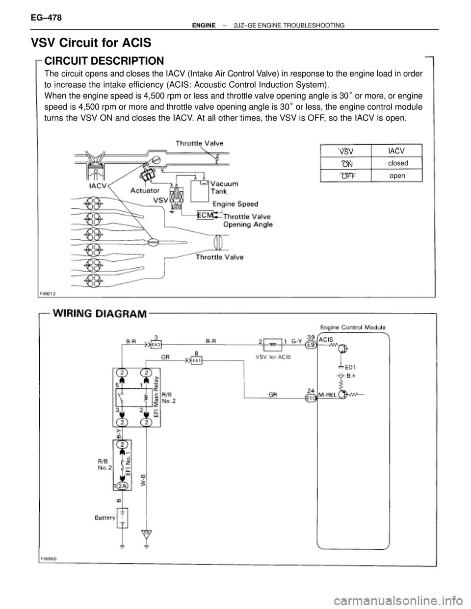
VSV Circuit for ACIS
CIRCUIT DESCRIPTION
The circuit opens and closes the IACV (Intake Air Control Valve) in response to the engine load in order
to increase the intake efficiency (ACIS: Acoustic Control Induction System).
When the engine speed is 4,500 rpm or less and throttle valve opening angle is 30° or more, or engine
speed is 4,500 rpm or more and throttle valve opening angle is 30° or less, the engine control module
turns the VSV ON and closes the IACV. At all other times, the VSV is OFF, so the IACV is open.
VSVIACV
ON
OFF
closed
open
EG±478± ENGINE2JZ±GE ENGINE TROUBLESHOOTING
Page 235 of 878
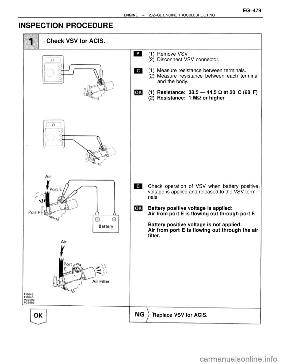
INSPECTION PROCEDURE
Check VSV for ACIS.
(1) Remove VSV.
(2) Disconnect VSV connector.
(1) Measure resistance between terminals.
(2) Measure resistance between each terminal
and the body.
(1) Resistance: 38.5 Ð 44.5 � at 20°C (68°F)
(2) Resistance: 1 M� or higher
Check operation of VSV when battery positive
voltage is applied and released to the VSV termi-
nals.
Battery positive voltage is applied:
Air from port E is flowing out through port F.
Battery positive voltage is not applied:
Air from port E is flowing out through the air
filter.
Replace VSV for ACIS.
± ENGINE2JZ±GE ENGINE TROUBLESHOOTINGEG±479
Page 236 of 878
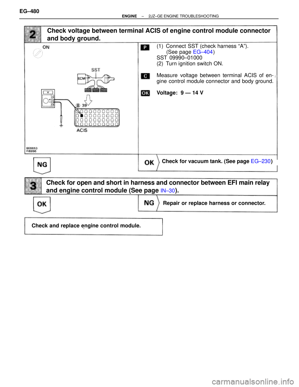
(See page EG±404)
(See page EG±230)
Check voltage between terminal ACIS of engine control module connector
and body ground.
(1) Connect SST (check harness ªAº).
(See page EG±404)
SST 09990±01000
(2) Turn ignition switch ON.
Measure voltage between terminal ACIS of en-
gine control module connector and body ground.
Voltage: 9 Ð 14 V
Check for vacuum tank. (See page EG±230)
Repair or replace harness or connector.
Check and replace engine control module.
Check for open and short in harness and connector between EFI main relay
and engine control module (See page
IN±30).
EG±480± ENGINE2JZ±GE ENGINE TROUBLESHOOTING
Page 237 of 878
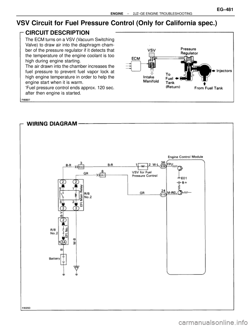
VSV Circuit for Fuel Pressure Control (Only for California spec.)
CIRCUIT DESCRIPTION
The ECM turns on a VSV (Vacuum Switching
Valve) to draw air into the diaphragm cham-
ber of the pressure regulator if it detects that
the temperature of the engine coolant is too
high during engine starting.
The air drawn into the chamber increases the
fuel pressure to prevent fuel vapor lock at
high engine temperature in order to help the
engine start when it is warm.
`Fuel pressure control ends approx. 120 sec.
after then engine is started.
± ENGINE2JZ±GE ENGINE TROUBLESHOOTINGEG±481
Page 238 of 878
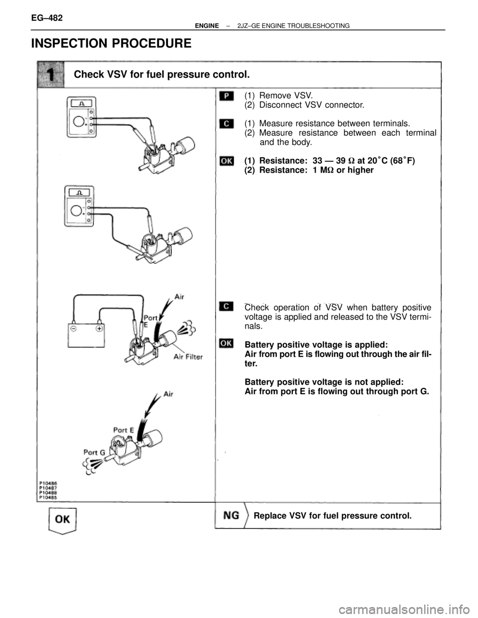
INSPECTION PROCEDURE
Check VSV for fuel pressure control.
(1) Remove VSV.
(2) Disconnect VSV connector.
(1) Measure resistance between terminals.
(2) Measure resistance between each terminal
and the body.
(1) Resistance: 33 Ð 39 � at 20°C (68°F)
(2) Resistance: 1 M� or higher
Check operation of VSV when battery positive
voltage is applied and released to the VSV termi-
nals.
Battery positive voltage is applied:
Air from port E is flowing out through the air fil-
ter.
Battery positive voltage is not applied:
Air from port E is flowing out through port G.
Replace VSV for fuel pressure control. EG±482
± ENGINE2JZ±GE ENGINE TROUBLESHOOTING
Page 239 of 878
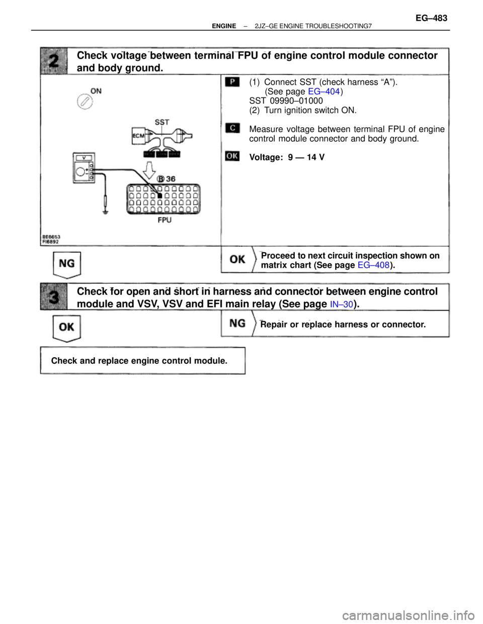
(See page EG±404)
Check voltage between terminal FPU of engine control module connector
and body ground.
(1) Connect SST (check harness ªAº).
(See page EG±404)
SST 09990±01000
(2) Turn ignition switch ON.
Measure voltage between terminal FPU of engine
control module connector and body ground.
Voltage: 9 Ð 14 V
Proceed to next circuit inspection shown on
matrix chart (See page EG±408).
Repair or replace harness or connector.
Check and replace engine control module.
Check for open and short in harness and connector between engine control
module and VSV, VSV and EFI main relay (See page
IN±30).
± ENGINE2JZ±GE ENGINE TROUBLESHOOTING7EG±483
Page 240 of 878
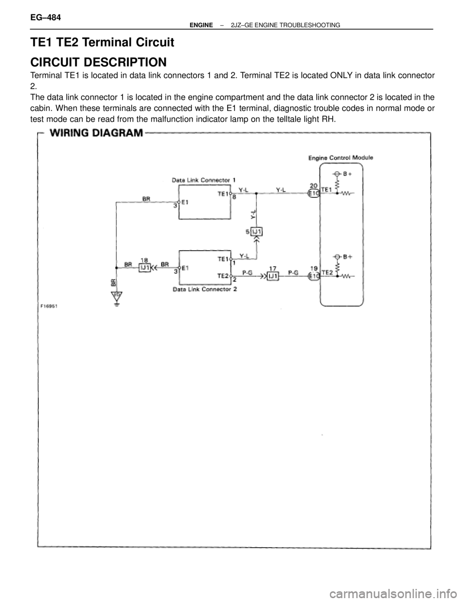
TE1 TE2 Terminal Circuit
CIRCUIT DESCRIPTION
Terminal TE1 is located in data link connectors 1 and 2. Terminal TE2 is located ONLY in data link connector
2.
The data link connector 1 is located in the engine compartment and the data link connector 2 is located in the
cabin. When these terminals are connected with the E1 terminal, diagnostic trouble codes in normal mode or
test mode can be read from the malfunction indicator lamp on the telltale light RH.
EG±484± ENGINE2JZ±GE ENGINE TROUBLESHOOTING
Trending: cruise control, display, fuse box, battery replacement, ABS, spark plugs, air filter
