engine TOYOTA SUPRA 2022 Owner's Manual
[x] Cancel search | Manufacturer: TOYOTA, Model Year: 2022, Model line: SUPRA, Model: TOYOTA SUPRA 2022Pages: 498, PDF Size: 104.06 MB
Page 161 of 498
159
3
3-1. CONTROLS
CONTROLS
can turn the engine.
Before the transmission lockout is
released, apply the parking brake
to prevent the ve hicle from rolling
away.
1 Apply the brakes and keep them
applied.
2 Press the start/stop button. The
starter must be heard to start
turning. Press and hold the
start/stop button.
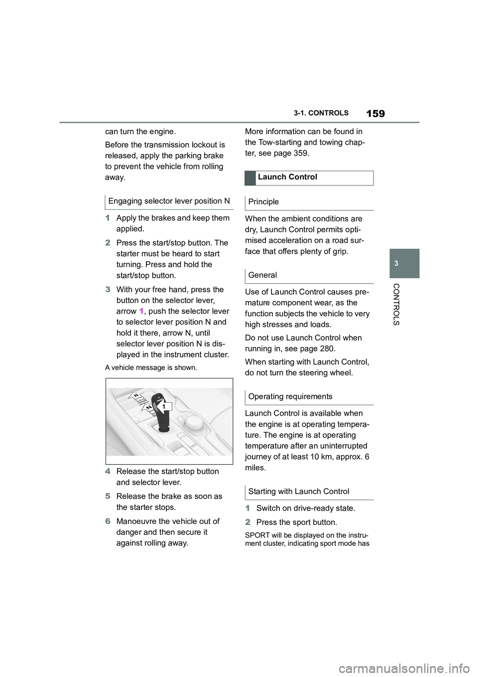
3 With your free hand, press the
button on the selector lever,
arrow 1, push the selector lever
to selector lever position N and
hold it there, arrow N, until
selector lever position N is dis-
played in the instrument cluster.
A vehicle message is shown.
4 Release the start/stop button
and selector lever.
5 Release the brake as soon as
the starter stops.
6 Manoeuvre the vehicle out of
danger and then secure it
against rolling away.
More information can be found in
the Tow-starting and towing chap-
ter, see page 359.
When the ambient conditions are
dry, Launch Control permits opti-
mised acceleration on a road sur-
face that offers plenty of grip.
Use of Launch Control causes pre-
mature component wear, as the
function subjects t he vehicle to very
high stresses and loads.
Do not use Launch Control when
running in, see page 280.
When starting with Launch Control,
do not turn the steering wheel.
Launch Control is available when
the engine is at operating tempera-
ture. The engine is at operating
temperature after an uninterrupted
journey of at least 10 km, approx. 6
miles.
1 Switch on drive-ready state.
2 Press the sport button.
SPORT will be displayed on the instru-
ment cluster, indicating sport mode has
Engaging selector lever position N
1
R
N
Launch Control
Principle
General
Operating requirements
Starting with Launch Control
Page 162 of 498
1603-1. CONTROLS
been selected.
3 Press the button.
TRACTION will be displayed on the instrument cluster and the VSC OFF
indicator lamp will illuminate.
4 Select the D selector lever posi-
tion.
5 Firmly depress the brake pedal
with your left foot.
6 Fully depress and hold the
accelerator pedal at the kick-
down position.
A flag symbol will be shown in the instrument cluster.
7 The engine speed will be
adjusted for launching. Release
the brake pedal within 3 sec-
onds.
Once Launch Control has been
used, the transmission requires
approximately 5 minutes to cool
down before Launch Control can be
used again. Launch Control adapts
to the ambient conditions when
used again.
To support driving stability, re-acti-
vate Vehicle Stab ility Control, VSC
as soon as possible.
An experienced driver may be able
to achieve better acceleration val-
ues in VSC OFF mode.
The sport mode switch influences
the driving dynamics characteristics
of the vehicle.
The following systems are influ-
enced, for example:
Engine characteristics.
Automatic transmission.
Adaptive variable suspension.
Steering.
Display in the instrument cluster.
Cruise Control. Using again during a journey
After using Launch Control
System limits
Sport mode switch
Principle
General
Overview
Page 164 of 498
1623-1. CONTROLS
This chapter describes all standard,
country-specific and special equip-
ment available for the model series.
It may therefore describe equip-
ment and functions which are not
installed in your vehicle, for exam-
ple on account of the special equip-
ment selected or the country
specification. This also applies to
safety-relevant functions and sys-
tems. Please comply with the rele-
vant laws and regulations when
using the corresponding functions
and systems.
The instrument cluster is a variable
display. When the sport mode
switch is used to change the driving
mode, the instrument cluster dis-
plays change to match the driving
mode.
Changes to the displays in the
instrument cluster can be deacti-
vated via Toyota Supra Command.
The displays in the instrument clus-
ter can sometimes differ from the
illustrations in th is Owner's Manual.
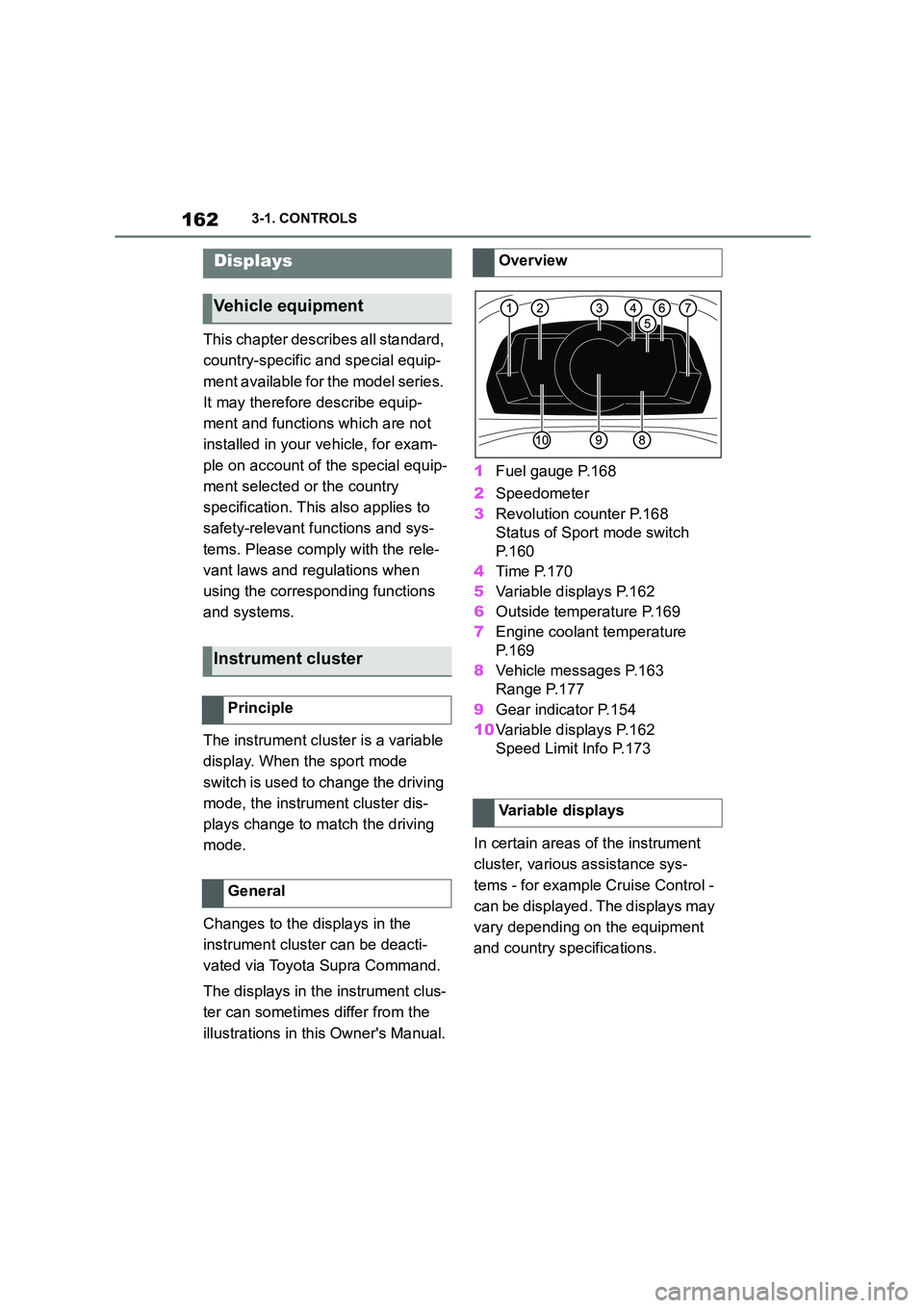
1 Fuel gauge P.168
2 Speedometer
3 Revolution counter P.168
Status of Sport mode switch
P. 1 6 0
4 Time P.170
5 Variable displays P.162
6 Outside temperature P.169
7 Engine coolant temperature
P. 1 6 9
8 Vehicle messages P.163
Range P.177
9 Gear indicator P.154
10 Variable displays P.162
Speed Limit Info P.173
In certain areas of the instrument
cluster, various assistance sys-
tems - for example Cruise Control -
can be displayed. The displays may
vary depending on the equipment
and country specifications.
Displays
Vehicle equipment
Instrument cluster
Principle
General
Overview
Variable displays
Page 169 of 498
167
3
3-1. CONTROLS
CONTROLS
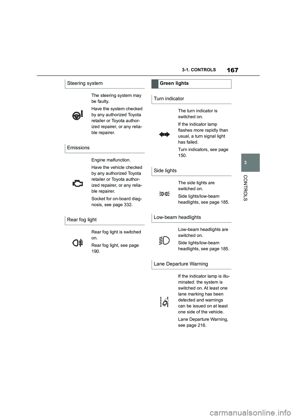
Steering system
The steering system may
be faulty.
Have the system checked
by any authorized Toyota
retailer or Toyota author-
ized repairer, or any relia-
ble repairer.
Emissions
Engine malfunction.
Have the vehicle checked
by any authorized Toyota
retailer or Toyota author-
ized repairer, or any relia-
ble repairer.
Socket for on-board diag-
nosis, see page 332.
Rear fog light
Rear fog light is switched
on.
Rear fog light, see page
190.
Green lights
Turn indicator
The turn indicator is
switched on.
If the indicator lamp
flashes more rapidly than
usual, a turn signal light
has failed.
Turn indicators, see page
150.
Side lights
The side lights are
switched on.
Side lights/low-beam
headlights, see page 185.
Low-beam headlights
Low-beam headlights are
switched on.
Side lights/low-beam
headlights, see page 185.
Lane Departure Warning
If the indicator lamp is illu-
minated: the system is
switched on. At least one
lane marking has been
detected and warnings
can be issued on at least
one side of the vehicle.
Lane Departure Warning,
see page 216.
Page 170 of 498
1683-1. CONTROLS
The current fill level of the fuel tank
is displayed.
The angle of the vehicle may cause
the display to fluctuate.
For notes on refuelling, see page
290.
It is vital to avoid engine speeds in
the red warning zone. In this zone,
the fuel supply is interrupted to pro-
tect the engine.
Depending on the equipment, the
shift lights on the revolution counter
indicate the maximum shift point at
which the best possible accelera-
tion can be achieved.
When the selected driving mode is
sport mode, a shift light will be dis-
played.
1 Select SPORT using the sport
mode switch.
2 Activate manual mode of the
transmission.
Automatic high-beam
Automatic high-beams
switched on.
The high-beam head-
lights are switched on and
off automatically depend-
ing on the traffic situation.
Automatic high-beam, see
page 188.
Blue lights
High-beam headlights
The high-beam head-
lights are switched on.
High-beam headlights,
see page 150.
Fuel gauge
Principle
General
Display
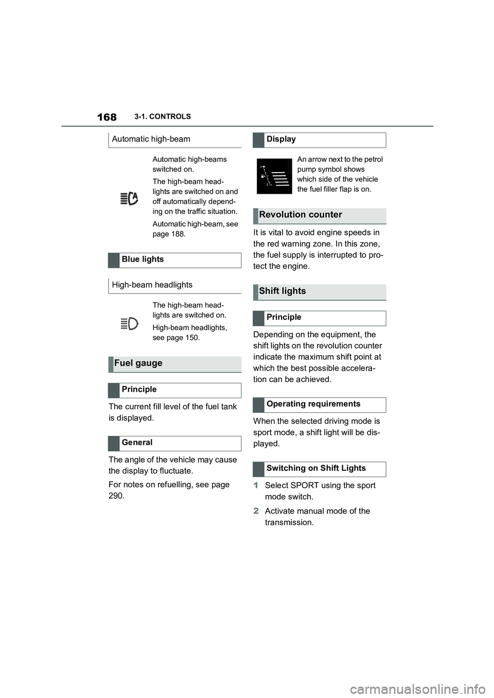
An arrow next to the petrol
pump symbol shows
which side of the vehicle
the fuel filler flap is on.
Revolution counter
Shift lights
Principle
Operating requirements
Switching on Shift Lights
Page 171 of 498
169
3
3-1. CONTROLS
CONTROLS
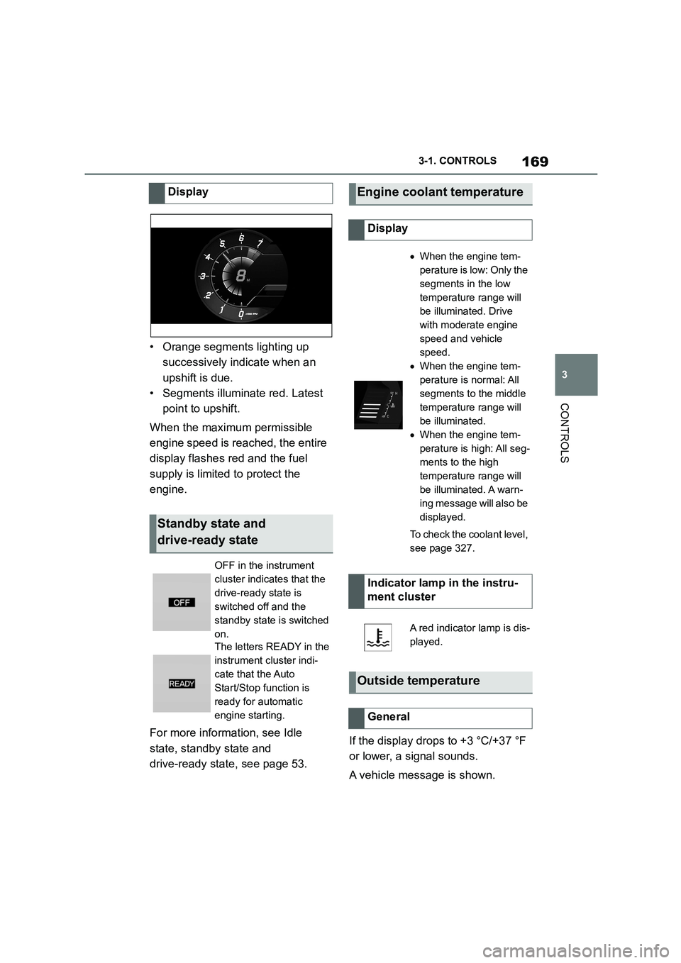
• Orange segments lighting up
successively indicate when an
upshift is due.
• Segments illuminate red. Latest
point to upshift.
When the maximum permissible
engine speed is reached, the entire
display flashes red and the fuel
supply is limited to protect the
engine.
For more informat ion, see Idle
state, standby state and
drive-ready state, see page 53.
If the display drops to +3 °C/+37 °F
or lower, a signal sounds.
A vehicle message is shown.
Display
Standby state and
drive-ready state
OFF in the instrument
cluster indicates that the
drive-ready state is
switched off and the
standby state is switched
on.
The letters READY in the
instrument cluster indi-
cate that the Auto
Start/Stop function is
ready for automatic
engine starting.
Engine coolant temperature
Display
When the engine tem-
perature is low: Only the
segments in the low
temperature range will
be illuminated. Drive
with moderate engine
speed and vehicle
speed.
When the engine tem-
perature is normal: All
segments to the middle
temperature range will
be illuminated.
When the engine tem-
perature is high: All seg-
ments to the high
temperature range will
be illuminated. A warn-
ing message will also be
displayed.
To check the coolant level,
see page 327.
Indicator lamp in the instru-
ment cluster
A red indicator lamp is dis-
played.
Outside temperature
General
Page 181 of 498
179
3
3-1. CONTROLS
CONTROLS
A vehicle message is displayed
briefly if the remaining range is low.
If a sporty driving style is adopted,
for example fast cornering, engine
function is not always ensured.
If the range drops below approxi-
mately 50 km, 30 miles the vehicle
message is continuously displayed.
■Safety note
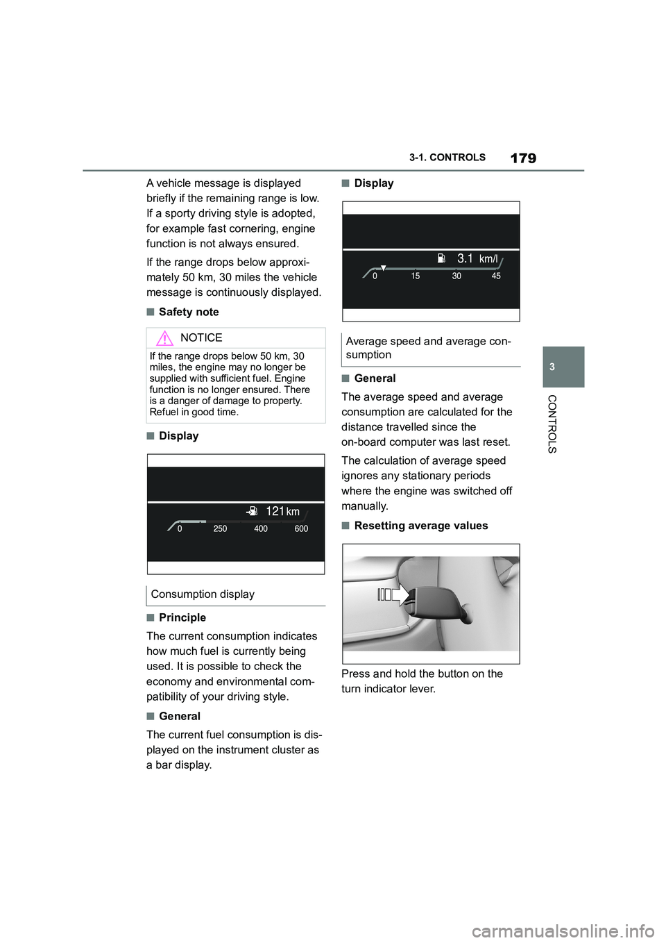
■Display
■Principle
The current consumption indicates
how much fuel is currently being
used. It is possible to check the
economy and environmental com-
patibility of your driving style.
■General
The current fuel consumption is dis-
played on the instrument cluster as
a bar display.
■Display
■General
The average speed and average
consumption are calculated for the
distance travelled since the
on-board computer was last reset.
The calculation of average speed
ignores any stationary periods
where the engine was switched off
manually.
■Resetting average values
Press and hold the button on the
turn indicator lever.
NOTICE
If the range drops below 50 km, 30
miles, the engine may no longer be supplied with sufficient fuel. Engine
function is no longer ensured. There
is a danger of damage to property. Refuel in good time.
Consumption display
Average speed and average con-
sumption
Page 184 of 498

1823-1. CONTROLS
• "Tyre Pressure Monitor": Sta-
tus of the Tyre Pressure Monitor,
see page 304
• "Engine oil leve l": Electronic
oil measurement, see page 324.
• "Vehicle messages": Vehicle
messages are stored in the
background and can be shown
on the Control Display. Display-
ing of saved vehicle messages,
see page 163.
• "Service requirements": dis-
play of the service requirements,
see page 170.
• "Remote maintenance call":
Remote maintenance call.
*: if equipped
The system projects important
information, for example the speed,
into the driver's field of vision.
The driver can register this informa-
tion without having to divert atten-
tion from the road.
Follow the instruct ions on cleaning
the Head-Up Display, see page
368.
Via Toyota Supra Command:
1 "My vehicle"
2 "System settings"
3 "Displays"
4 "Head-up display"
5 "Head-up display"
The following information is dis-
played in the Head-Up Display:
Speed.
Navigation instructions.
Vehicle messages.
Selection list in the instrument
cluster.
Driver Assistance Systems.
Some of this information is only
shown briefly when needed.
Overview of the information
Head-Up Display*
Principle
General
Overview
Switching on/off
Display
Overview
Page 204 of 498
2023-1. CONTROLS
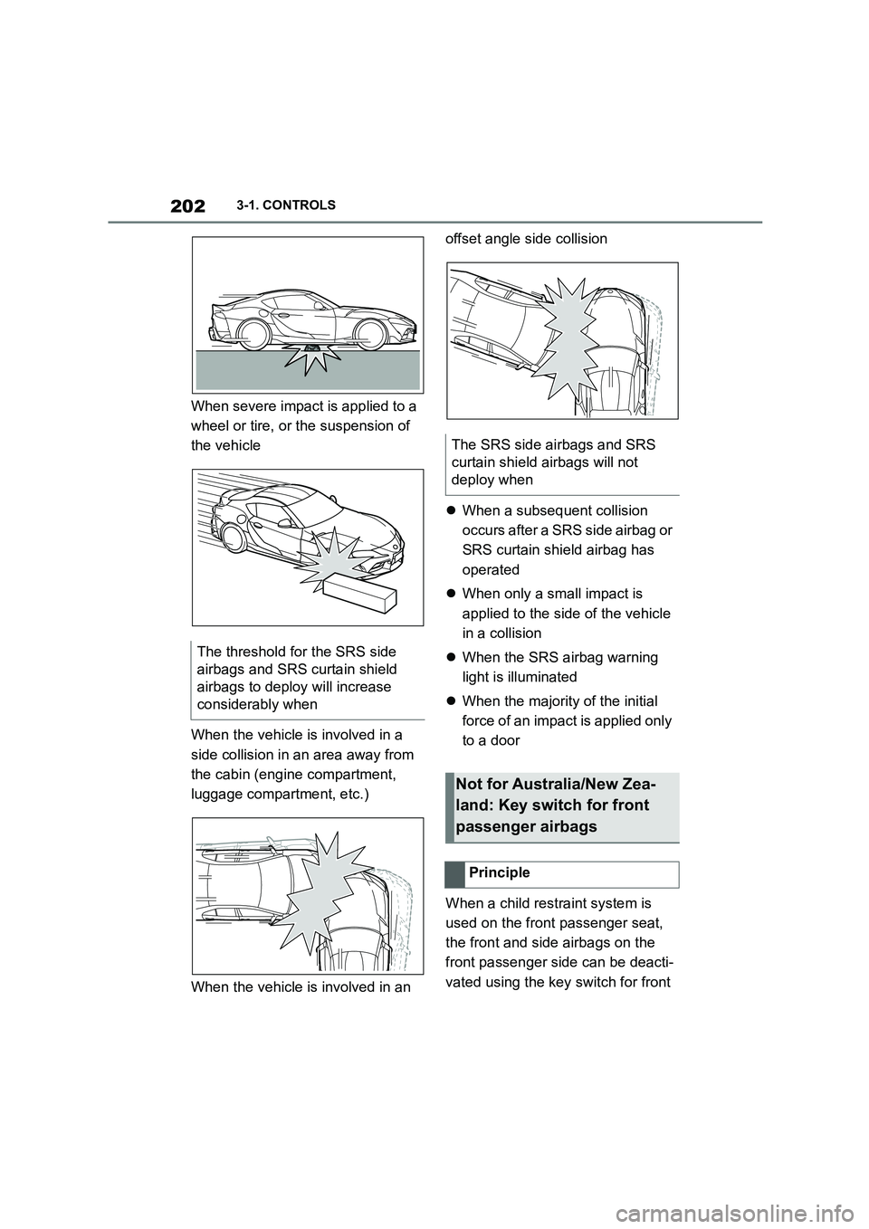
When severe impact is applied to a
wheel or tire, or the suspension of
the vehicle
When the vehicle is involved in a
side collision in an area away from
the cabin (engine compartment,
luggage compartment, etc.)
When the vehicle is involved in an
offset angle side collision
When a subsequent collision
occurs after a SRS side airbag or
SRS curtain shield airbag has
operated
When only a small impact is
applied to the side of the vehicle
in a collision
When the SRS airbag warning
light is illuminated
When the majority of the initial
force of an impact is applied only
to a door
When a child restraint system is
used on the front passenger seat,
the front and side airbags on the
front passenger side can be deacti-
vated using the key switch for front
The threshold for the SRS side
airbags and SRS curtain shield
airbags to deploy will increase
considerably when
The SRS side airbags and SRS
curtain shield airbags will not
deploy when
Not for Australia/New Zea-
land: Key switch for front
passenger airbags
Principle
Page 213 of 498
211
3
3-1. CONTROLS
CONTROLS
At speeds over approx. 250 km/h,
155 mph, the system is temporarily
disabled. As soon as the speed
drops back below this value, the
system responds once again
according to its settings.
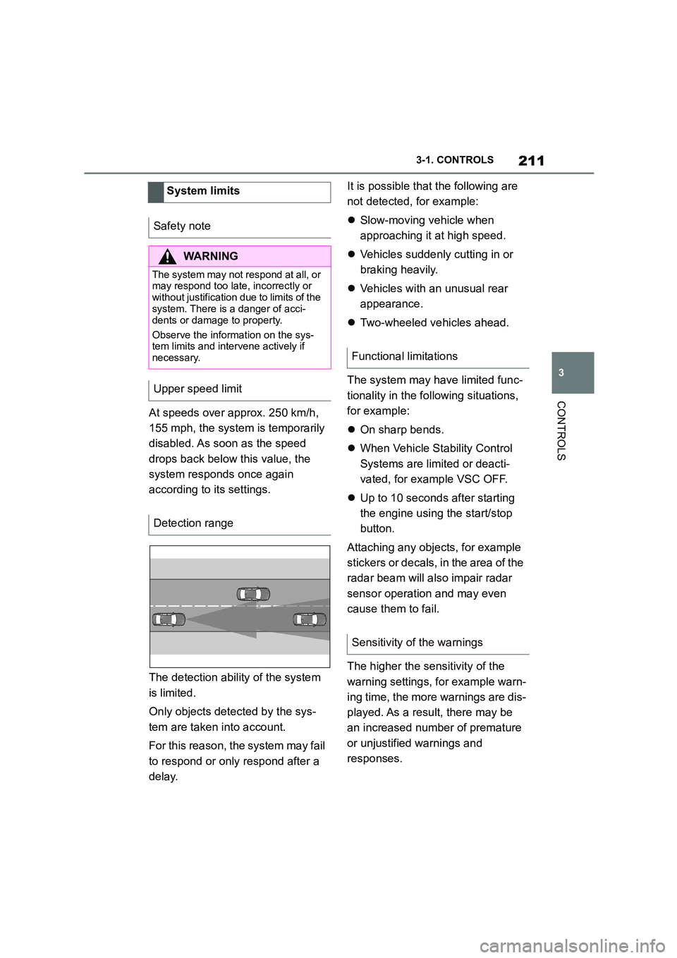
The detection ability of the system
is limited.
Only objects detected by the sys-
tem are taken into account.
For this reason, the system may fail
to respond or only respond after a
delay.
It is possible that the following are
not detected, for example:
Slow-moving vehicle when
approaching it at high speed.
Vehicles suddenly cutting in or
braking heavily.
Vehicles with an unusual rear
appearance.
Two-wheeled vehicles ahead.
The system may have limited func-
tionality in the following situations,
for example:
On sharp bends.
When Vehicle Stability Control
Systems are limited or deacti-
vated, for example VSC OFF.
Up to 10 seconds after starting
the engine using the start/stop
button.
Attaching any objects, for example
stickers or decals, in the area of the
radar beam will also impair radar
sensor operation and may even
cause them to fail.
The higher the sensitivity of the
warning settings, fo r example warn-
ing time, the more warnings are dis-
played. As a result, there may be
an increased number of premature
or unjustified warnings and
responses.
System limits
Safety note
WA R N I N G
The system may not re spond at all, or may respond too late, incorrectly or
without justification due to limits of the
system. There is a danger of acci-
dents or damage to property.
Observe the information on the sys-
tem limits and intervene actively if
necessary.
Upper speed limit
Detection range
Functional limitations
Sensitivity of the warnings