VOLKSWAGEN JETTA 1998 Owner's Manual
Manufacturer: VOLKSWAGEN, Model Year: 1998, Model line: JETTA, Model: VOLKSWAGEN JETTA 1998Pages: 339, PDF Size: 2.35 MB
Page 21 of 339
Downloaded from www.Manualslib.com manuals search engine 01-18
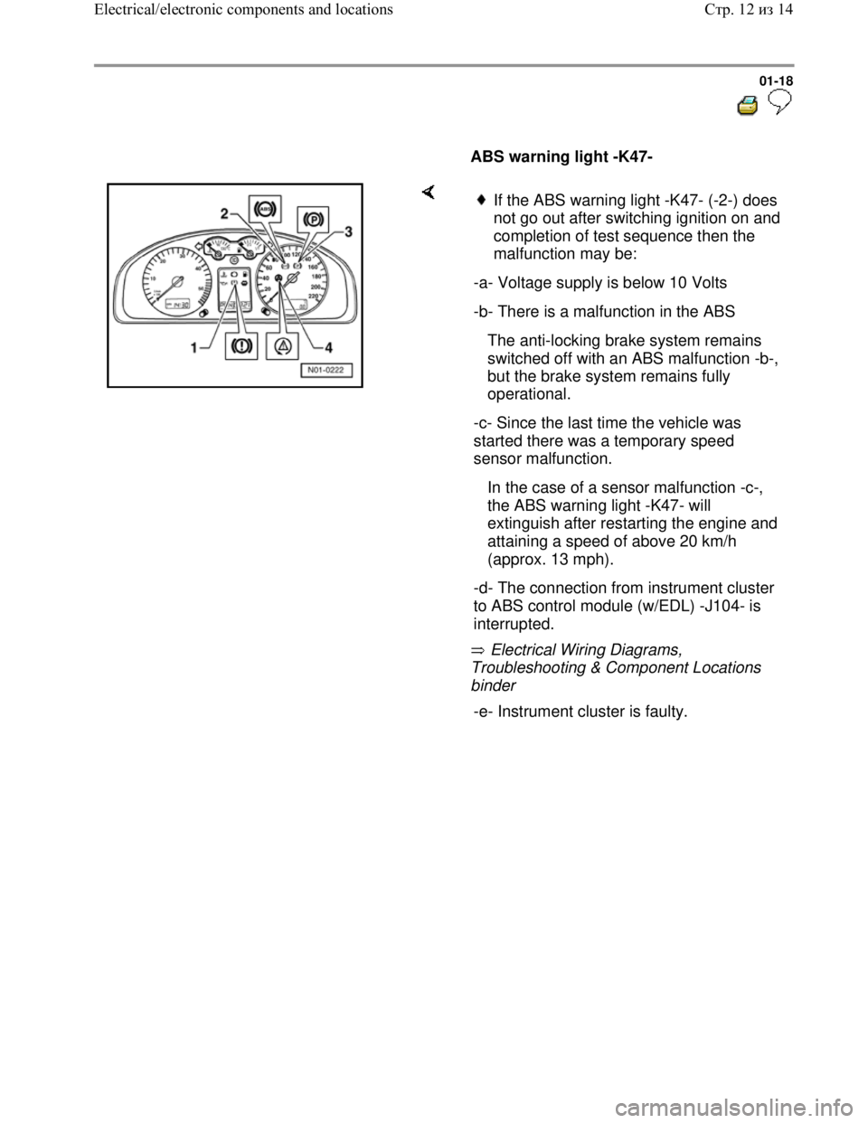
ABS warning light -K47-
Electrical Wiring Diagrams,
Troubleshooting & Component Locations
binder
If the ABS warning light -K47- (-2-) does
not go out after switching ignition on and
completion of test sequence then the
malfunction may be:
-a- Voltage supply is below 10 Volts
-b- There is a malfunction in the ABS
The anti-locking brake system remains
switched off with an ABS malfunction -b-,
but the brake system remains fully
operational.
-c- Since the last time the vehicle was
started there was a temporary speed
sensor malfunction.
In the case of a sensor malfunction -c-,
the ABS warning light -K47- will
extinguish after restarting the engine and
attaining a speed of above 20 km/h
(approx. 13 mph).
-d- The connection from instrument cluster
to ABS control module (w/EDL) -J104- is
interrupted.
-e- Instrument cluster is faulty.
Стр. 12из 14 Electrical/electronic components and locations
Page 22 of 339
Downloaded from www.Manualslib.com manuals search engine 01-19
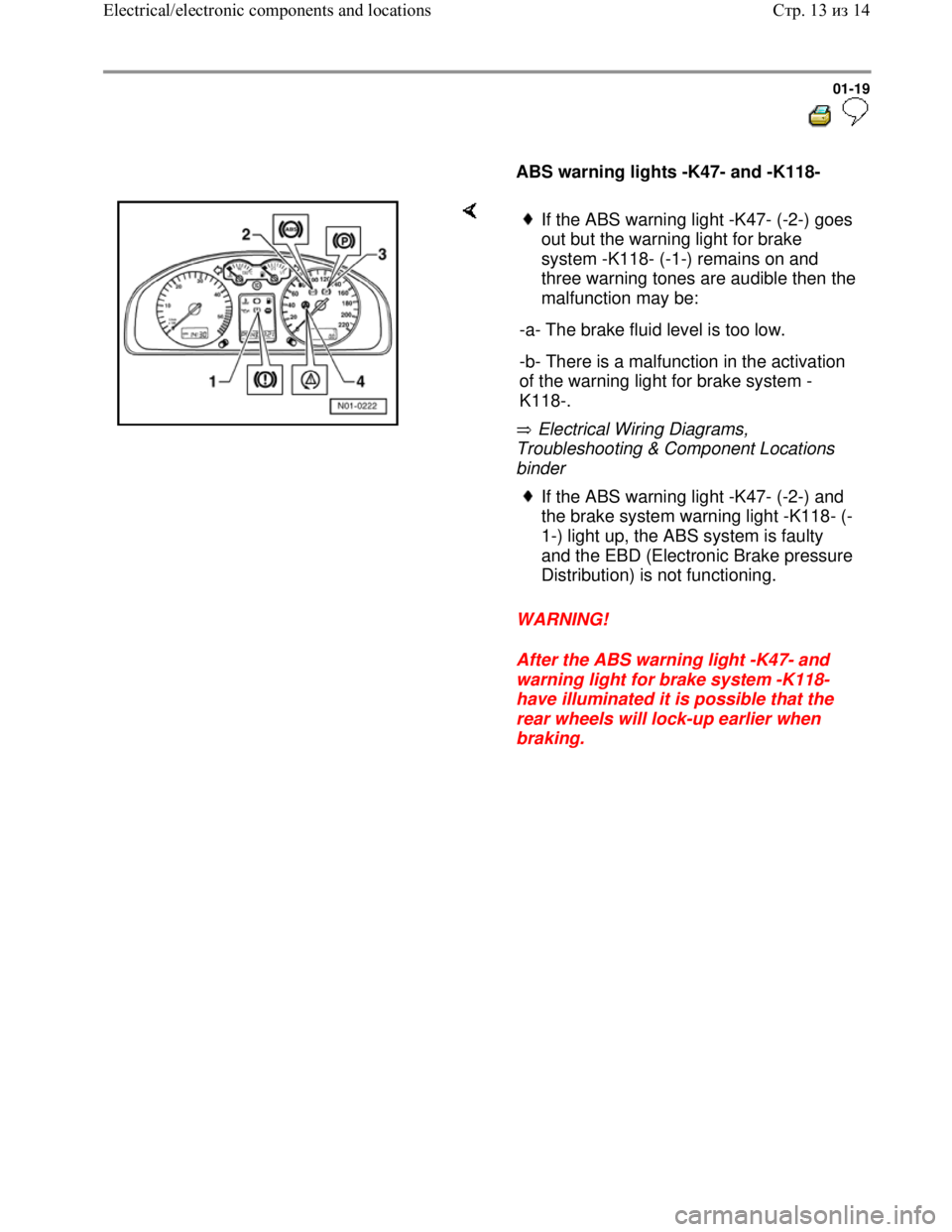
ABS warning lights -K47- and -K118-
Electrical Wiring Diagrams,
Troubleshooting & Component Locations
binder
WARNING!
After the ABS warning light -K47- and
warning light for brake system -K118-
have illuminated it is possible that the
rear wheels will lock-up earlier when
braking.
If the ABS warning light -K47- (-2-) goes
out but the warning light for brake
system -K118- (-1-) remains on and
three warning tones are audible then the
malfunction may be:
-a- The brake fluid level is too low.
-b- There is a malfunction in the activation
of the warning light for brake system -
K118-.
If the ABS warning light -K47- (-2-) and
the brake system warning light -K118- (-
1-) light up, the ABS system is faulty
and the EBD (Electronic Brake pressure
Distribution) is not functioning.
Стр. 13из 14 Electrical/electronic components and locations
Page 23 of 339
Downloaded from www.Manualslib.com manuals search engine 01-20
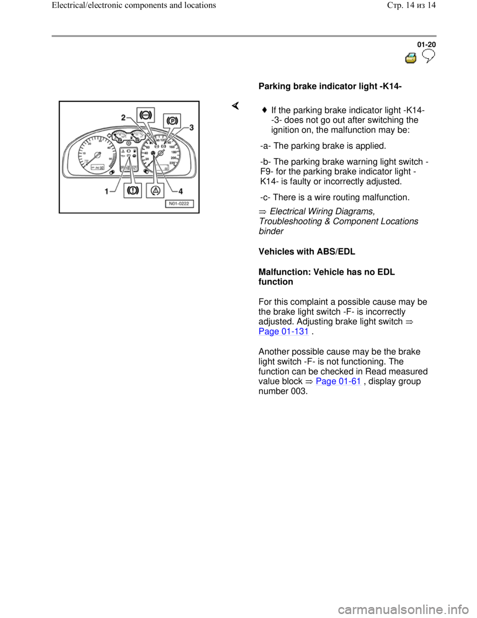
Parking brake indicator light -K14-
Electrical Wiring Diagrams,
Troubleshooting & Component Locations
binder
Vehicles with ABS/EDL
Malfunction: Vehicle has no EDL
function
For this complaint a possible cause may be
the brake light switch -F- is incorrectly
adjusted. Adjusting brake light switch
Page 01
-131 .
Another possible cause may be the brake
light switch -F- is not functioning. The
function can be checked in Read measured
value block Page 01
-61 , display group
number 003.
If the parking brake indicator light -K14-
-3- does not go out after switching the
ignition on, the malfunction may be:
-a- The parking brake is applied.
-b- The parking brake warning light switch -
F9- for the parking brake indicator light -
K14- is faulty or incorrectly adjusted.
-c- There is a wire routing malfunction.
Стр. 14из 14 Electrical/electronic components and locations
Page 24 of 339
Downloaded from www.Manualslib.com manuals search engine 01-21
ABS ITT Mk 20 IE On Board
Diagnostic (OBD) program
All functions which could previously be
performed with V.A.G 1551 can also be
performed with the new tester VAS 5051.
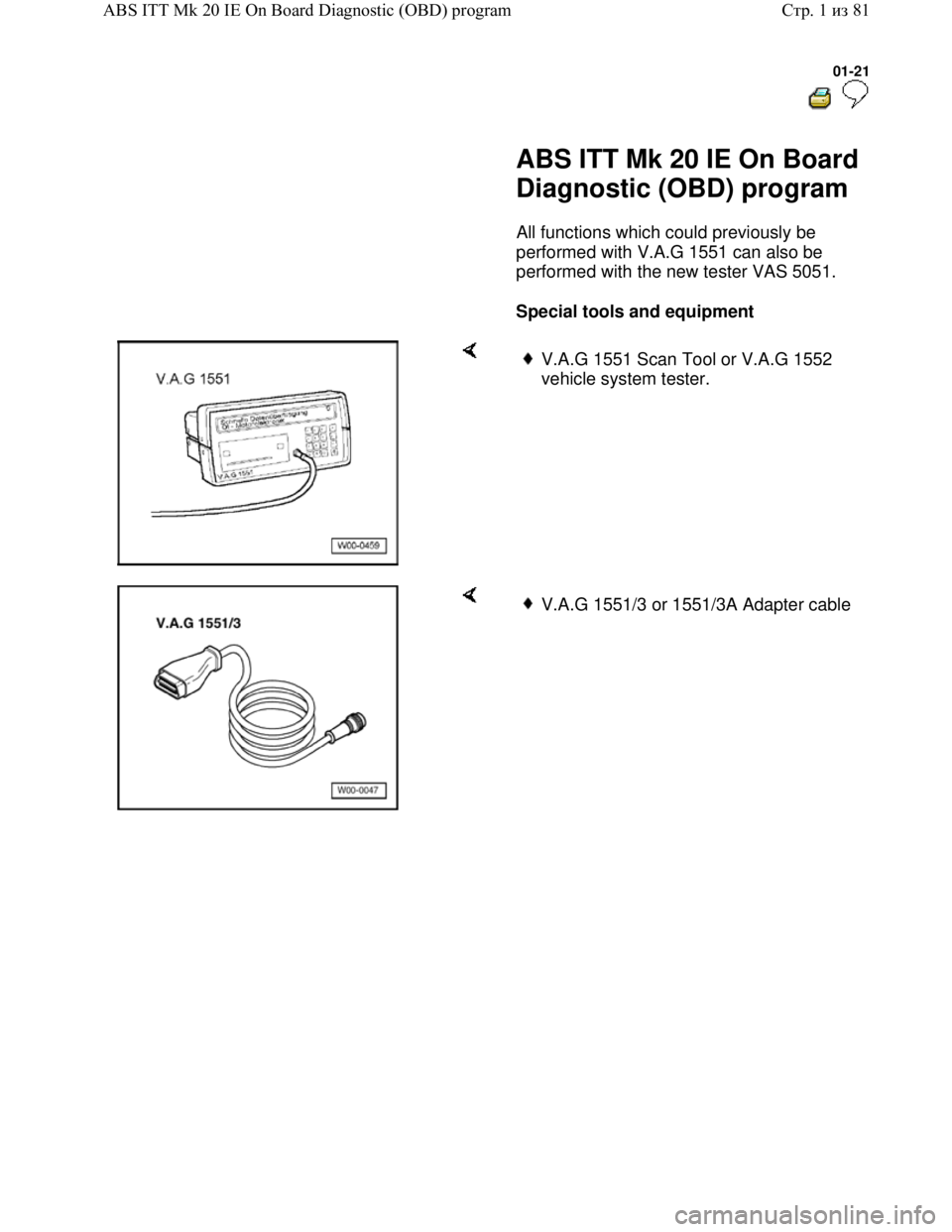
Special tools and equipment
V.A.G 1551 Scan Tool or V.A.G 1552
vehicle system tester.
V.A.G 1551/3 or 1551/3A Adapter cable
Стр. 1из 81 ABS ITT Mk 20 IE On Board Diagnostic (OBD) program
Page 25 of 339
Downloaded from www.Manualslib.com manuals search engine 01-22
Test requirements
The tires installed to all wheels must be of
the same (approved) size; tires inflated to
prescribed pressure.
Mechanical/hydraulic parts of the brake
system including brake light switch and
brake lights OK.
Hydraulic lines and connections not leaking
(visual check of hydraulic unit, brake
calipers, wheel cylinders, tandem master
brake cylinder).
Wheel bearings and wheel bearing play
OK.
ABS control module (w/EDL) -J104- is
correctly bolted to hydraulic unit -N55-.
Connector on ABS control module (w/EDL)
-J104- correctly plugged-in (retainer is
engaged).
Check contacts of ABS components for
damage and correct seating.
All fuses OK according to wiring diagram
(remove fuse from fuse holder to check).
Supply voltage OK (at least 10.0 V).
Стр. 2из 81 ABS ITT Mk 20 IE On Board Diagnostic (OBD) program
Page 26 of 339
Downloaded from www.Manualslib.com manuals search engine 01-23
V.A.G 1551 Scan Tool, connecting and
selecting function
Note:
All functions which could previously be
performed with V.A.G 1551 can also be
performed with the new tester VAS 5051.
The ABS function is switched off in the control
module during the On Board Diagnostic (OBD)
.
The Diagnostic Trouble Code (DTC) memory
can be erased after successful checking and
repair.
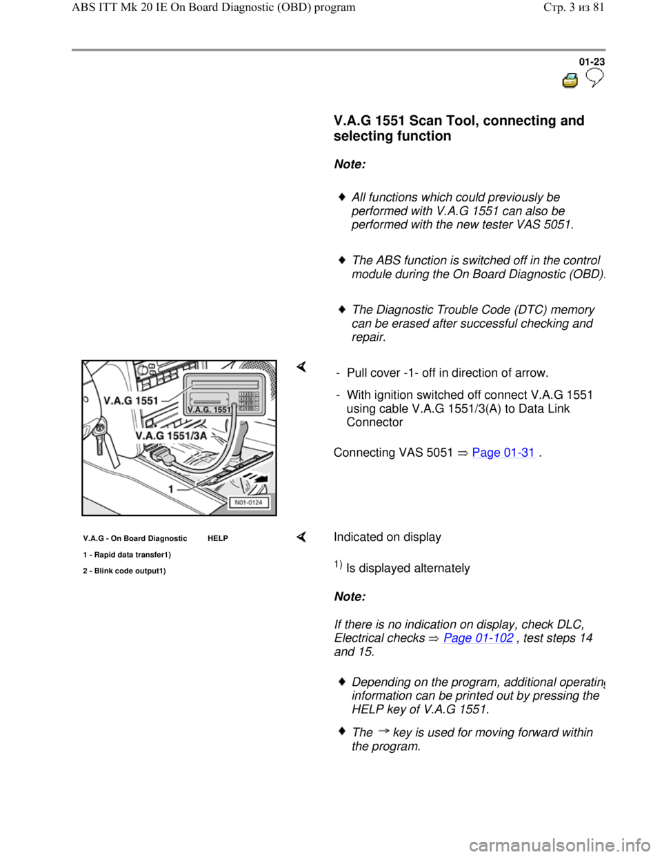
Connecting VAS 5051 Page 01-31 . - Pull cover -1- off in direction of arrow.
- With ignition switched off connect V.A.G 1551
using cable V.A.G 1551/3(A) to Data Link
Connector
V.A.G - On Board Diagnostic HELP
1 - Ra
pid data transfer1)
2 - Blink code output1)
Indicated on display
1) Is displayed alternately
Note:
If there is no indication on display, check DLC,
Electrical checks Page 01
-102 , test steps 14
and 15.
Depending on the program, additional operating
information can be printed out by pressing the
HELP key of V.A.G 1551.
The key is used for moving forward within
the program.
Стр. 3из 81 ABS ITT Mk 20 IE On Board Diagnostic (OBD) program
Page 27 of 339
Downloaded from www.Manualslib.com manuals search engine 01-24
The PRINT key is used for switching on the
printer (warning lamp in key comes on).
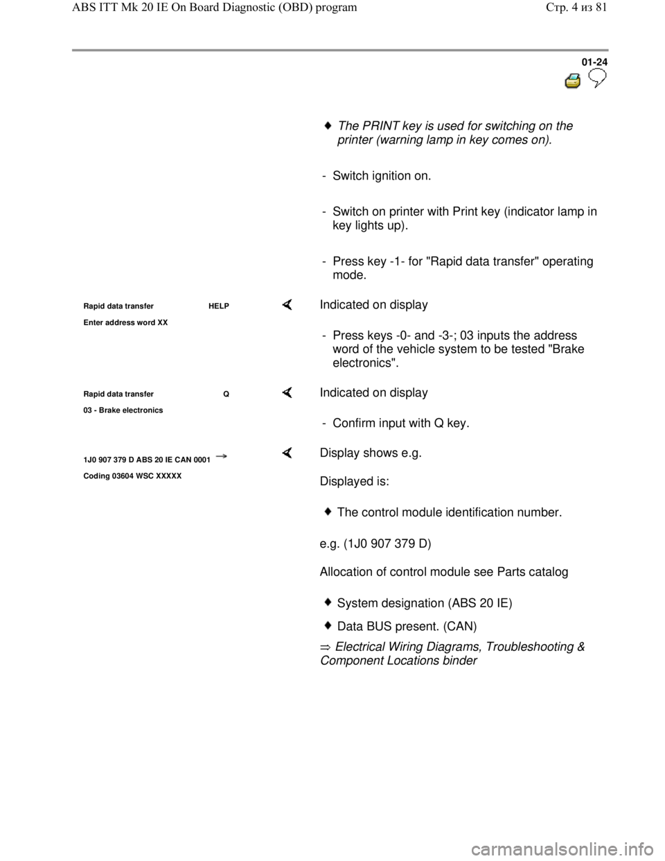
- Switch ignition on.
- Switch on printer with Print key (indicator lamp in
key lights up).
- Press key -1- for "Rapid data transfer" operating
mode.
Rapid data transfer HELP
Enter address word XX Indicated on display
- Press keys -0- and -3-; 03 inputs the address
word of the vehicle system to be tested "Brake
electronics".
Rapid data transfer Q
03 - Brake electronics Indicated on display
- Confirm input with Q key.
1J0 907 379 D ABS 20 IE CAN 0001
Coding 03604 WSC XXXXX
Display shows e.g.
Displayed is:
e.g. (1J0 907 379 D)
Allocation of control module see Parts catalog
Electrical Wiring Diagrams, Troubleshooting &
Component Locations binder
The control module identification number.
System designation (ABS 20 IE)
Data BUS present. (CAN)
Стр. 4из 81 ABS ITT Mk 20 IE On Board Diagnostic (OBD) program
Page 28 of 339
Downloaded from www.Manualslib.com manuals search engine 01-25
Control module code (03604).
Coding control module Page 01
-58
Workshop code
V.A.G 1551 Scan Tool operating
instructions
If the control module identification number
does not appear Summary of selectable
functions Page 01
-27
-
Press key.
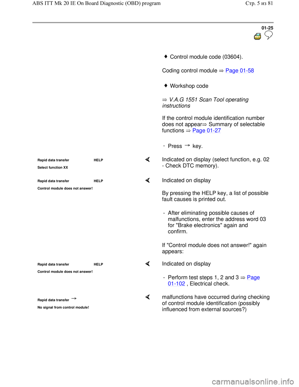
Rapid data transfer HELP
Select function XX Indicated on display (select function, e.g. 02
- Check DTC memory).
Rapid data transfer HELP
Control module does not answer! Indicated on display
By pressing the HELP key, a list of possible
fault causes is printed out.
If "Control module does not answer!" again
appears: - After eliminating possible causes of
malfunctions, enter the address word 03
for "Brake electronics" again and
confirm.
Rapid data transfer HELP
Control module does not answer! Indicated on display
- Perform test steps 1, 2 and 3 Page
01-102 , Electrical check.
Rapid data transfer
No signal from control module!
malfunctions have occurred during checking
of control module identification (possibly
influenced from external sources?)
Стр. 5из 81 ABS ITT Mk 20 IE On Board Diagnostic (OBD) program
Page 29 of 339
Downloaded from www.Manualslib.com manuals search engine 01-26
- Check DLC as well as voltage supply and
Ground connection for ABS Control Module
(w/EDL) -J104-, Electrical check, Page 01
-
102 .
- After repairing possible causes of malfunction,
again enter address word 03 for "Brake
electronics" and confirm with Q key.
Стр. 6из 81 ABS ITT Mk 20 IE On Board Diagnostic (OBD) program
Page 30 of 339
Downloaded from www.Manualslib.com manuals search engine 01-27
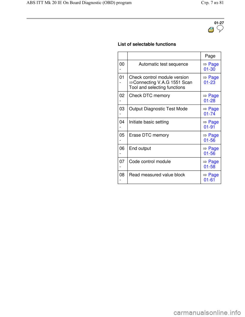
List of selectable functions
Page
00
- Automatic test sequence Page
01-30
01
- Check control module version
Connecting V.A.G 1551 Scan
Tool and selecting functions Page
01-23
02
- Check DTC memory Page
01-28
03
- Output Diagnostic Test Mode Page
01-74
04
- Initiate basic setting Page
01-91
05
- Erase DTC memory Page
01-56
06
- End output Page
01-56
07
- Code control module Page
01-58
08
- Read measured value block Page
01-61
Стр. 7из 81 ABS ITT Mk 20 IE On Board Diagnostic (OBD) program