YAMAHA DT125R 2000 Workshop Manual
Manufacturer: YAMAHA, Model Year: 2000, Model line: DT125R, Model: YAMAHA DT125R 2000Pages: 91, PDF Size: 4.67 MB
Page 51 of 91
6-14
PERIODIC MAINTENANCE AND MINOR REPAIR
1
2
3
4
56
7
8
98.Install the reservoir tank hose.
9.Pour the recommended coolant
into the radiator until it is full.
Recommended antifreeze:
High quality ethylene glycol
antifreeze containing
corrosion inhibitors for
aluminum engines.
Antifreeze and water mixing ratio:
1:1
Total amount:
1.05 L
Reservoir tank capacity:
0.35 L
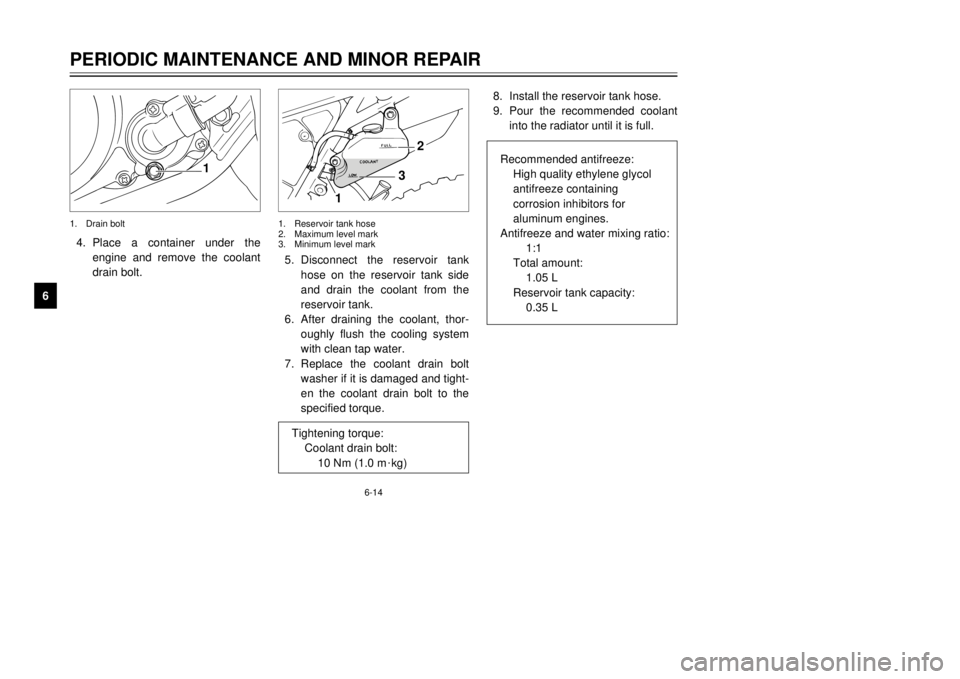
4.Place a container under the
engine and remove the coolant
drain bolt.5.Disconnect the reservoir tank
hose on the reservoir tank side
and drain the coolant from the
reservoir tank.
6.After draining the coolant, thor-
oughly flush the cooling system
with clean tap water.
7.Replace the coolant drain bolt
washer if it is damaged and tight-
en the coolant drain bolt to the
specified torque.
1
13
2
1.Drain bolt1.Reservoir tank hose
2.Maximum level mark
3.Minimum level mark
Tightening torque:
Coolant drain bolt:
10 Nm (1.0 m
0kg)
3MB-9-E7 12/27/00 2:52 PM Page 50
Page 52 of 91
6-15
PERIODIC MAINTENANCE AND MINOR REPAIR
1
2
3
4
56
7
8
9
EC000080
cCHard water or salt water is harmful
to the engine. You may use dis-
tilled water if you canÕt get soft
water.10.Install the radiator cap.
11.Run the engine several minutes.
Stop the engine and recheck the
coolant level in the radiator. If it
is low, add more coolant until it
reaches the top of the radiator.
12.Install the radiator cap stopper
bolt.
13.Fill the reservoir tank with
coolant up to maximum level.
14.Install the reservoir tank cap and
check for coolant leakage.NOTE:
If any leakage is found, ask a
Yamaha dealer to inspect the cooling
system.15.Install the cowling and the panel.
1
EAU03107
Air filterThe air filter should be cleaned at the
specified intervals. It should be
cleaned more frequently when riding
in unusually wet or dusty areas.
1.Remove panel D. (See page 6-9
for panel removal and installation
procedures.)
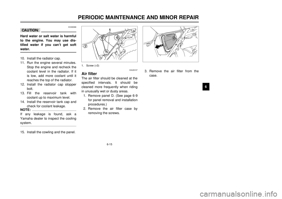
2.Remove the air filter case by
removing the screws.1.Screw (´3)
3.Remove the air filter from the
case.
3MB-9-E7 12/27/00 2:52 PM Page 51
Page 53 of 91
6-16
PERIODIC MAINTENANCE AND MINOR REPAIR
1
2
3
4
56
7
8
96.Insert the air filter guide into the
air filter and install it in the case.
7.Install the air filter case cover
and panel by installing the
screws.
EC000082
cC8
8
Make sure the air filter is prop-
erly seated in the air filter
case.
8 8
The engine should never be
run without the air filter
installed. Excessive piston
and/or cylinder wear may
result.
EAU00629
Carburetor adjustmentThe carburetor is a vital part of the
engine and requires very sophisticat-
ed adjustment. Most adjustments
should be left to a Yamaha dealer
who has the professional knowledge
and experience to do so. However,
the following may be serviced by the
owner as part of routine mainte-
nance.
EC000094
cCThe carburetor was set at the
Yamaha factory after many tests. If
the settings are changed, poor
engine performance and damage
may result.
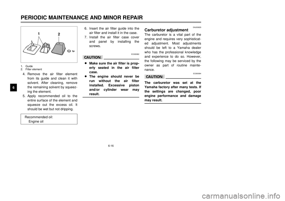
4.Remove the air filter element
from its guide and clean it with
solvent. After cleaning, remove
the remaining solvent by squeez-
ing the element.
5.Apply recommended oil to the
entire surface of the element and
squeeze out the excess oil. It
should be wet but not dripping.
1
2
1.Guide
2.Filter element
Recommended oil:
Engine oil
3MB-9-E7 12/27/00 2:52 PM Page 52
Page 54 of 91
6-17
PERIODIC MAINTENANCE AND MINOR REPAIR
1
2
3
4
56
7
8
9
b
a
1
EAU00632
Idle speed adjustment1.Start the engine and warm it up
for a few minutes at approxi-
mately 1,000 to 2,000 r/min.
Occasionally rev the engine to
4,000 to 5,000 r/min. The engine
is warm when it quickly responds
to the throttle.
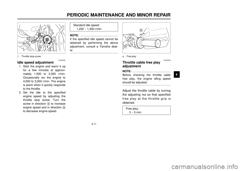
2.Set the idle to the specified
engine speed by adjusting the
throttle stop screw. Turn the
screw in direction ato increase
engine speed and in direction b
to decrease engine speed.1.Throttle stop screw
NOTE:
If the specified idle speed cannot be
obtained by performing the above
adjustment, consult a Yamaha deal-
er.
Standard idle speed:
1,250 ~ 1,450 r/min
a
EAU00634
Throttle cable free play
adjustmentNOTE:
Before checking the throttle cable
free play, the engine idling speed
should be adjusted.Adjust the throttle cable by turning
the adjusting nut so that specified
free play at the throttle grip is
obtained.a.Free play
Free play:
3 ~ 5 mm
3MB-9-E7 12/27/00 2:52 PM Page 53
Page 55 of 91
6-18
PERIODIC MAINTENANCE AND MINOR REPAIR
1
2
3
4
56
7
8
9
EAU00652
TiresTo ensure maximum performance,
long service and safe operation, note
the following:
Tire air pressure
Always check and adjust the tire
pressure before operating the motor-
cycle.
EW000082
wTire inflation pressure should be
checked and adjusted when the
temperature of the tire equals the
ambient air temperature. Tire infla-
tion pressure must be adjusted
according to total weight of cargo,
rider, passenger, and accessories
(fairing, saddlebags, etc. if
approved for this model), and vehi-
cle speed.
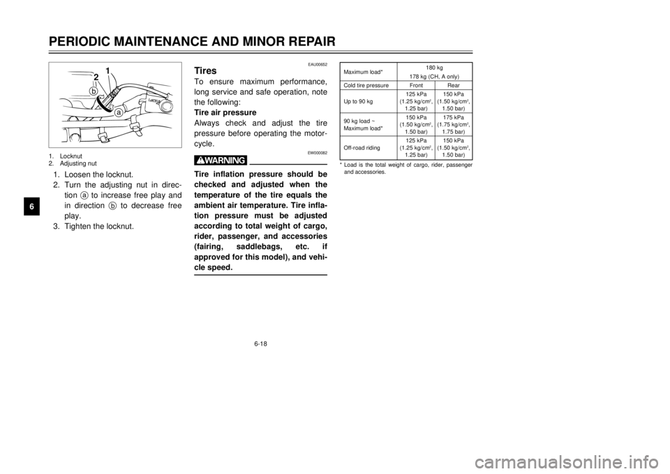
*Load is the total weight of cargo, rider, passenger
and accessories. Maximum load*180 kg
178 kg (CH, A only)
Cold tire pressureFrontRear
125 kPa150 kPa
Up to 90 kg(1.25 kg/cm
2,(1.50 kg/cm
2,
1.25 bar)1.50 bar)
90 kg load ~150 kPa175 kPa
Maximum load*(1.50 kg/cm
2,(1.75 kg/cm
2,
1.50 bar) 1.75 bar)
125 kPa150 kPa
Off-road riding(1.25 kg/cm
2,(1.50 kg/cm
2,
1.25 bar)1.50 bar)
1.Loosen the locknut.
2.Turn the adjusting nut in direc-
tion ato increase free play and
in direction bto decrease free
play.
3.Tighten the locknut.
2
1
b
a
1.Locknut
2.Adjusting nut
3MB-9-E7 12/27/00 2:52 PM Page 54
Page 56 of 91
6-19
PERIODIC MAINTENANCE AND MINOR REPAIR
1
2
3
4
56
7
8
9
EW000083
wProper loading of your motorcycle
is important for several character-
istics of your motorcycle, such as
handling, braking, performance
and safety. Do not carry loosely
packed items that can shift.
Securely pack your heaviest items
close to the center of the motorcy-
cle, and distribute the weight even-
ly from side to side. Properly
adjust the suspension for your
load, and check the condition and
pressure of your tires. NEVER
OVERLOAD YOUR MOTORCYCLE.
Make sure the total weight of the
cargo, rider, passenger, and
accessories (fairing, saddlebags,
etc. if approved for this model)
does not exceed the maximum
load of the motorcycle. Operation
of an overloaded motorcycle could
cause tire damage, an accident, or
even injury.
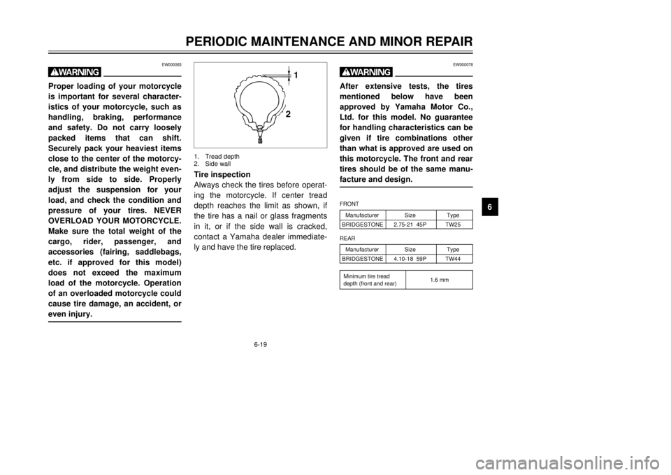
Tire inspection
Always check the tires before operat-
ing the motorcycle. If center tread
depth reaches the limit as shown, if
the tire has a nail or glass fragments
in it, or if the side wall is cracked,
contact a Yamaha dealer immediate-
ly and have the tire replaced.
EW000078
wAfter extensive tests, the tires
mentioned below have been
approved by Yamaha Motor Co.,
Ltd. for this model. No guarantee
for handling characteristics can be
given if tire combinations other
than what is approved are used on
this motorcycle. The front and rear
tires should be of the same manu-
facture and design.
1
2
1.Tread depth
2.Side wall
ManufacturerSizeType
BRIDGESTONE2.75-21 45PTW25FRONTManufacturerSizeType
BRIDGESTONE4.10-18 59PTW44REAR
Minimum tire tread
1.6 mm
depth (front and rear)
3MB-9-E7 12/27/00 2:52 PM Page 55
Page 57 of 91

6-20
PERIODIC MAINTENANCE AND MINOR REPAIR
1
2
3
4
56
7
8
9
EAU00685
WheelsTo ensure maximum performance,
long service, and safe operation, note
the following:
8Always inspect the wheels
before a ride. Check for cracks,
bends or warpage of the wheel.
Be sure the spokes are tight and
undamaged. If any abnormal
condition exists in a wheel, con-
sult a Yamaha dealer. Do not
attempt even small repairs to the
wheel. If a wheel is deformed or
cracked, it must be replaced.
8Tires and wheels should be bal-
anced whenever either one is
changed or replaced. Failure to
have a wheel balanced can
result in poor performance,
adverse handling characteristics,
and shortened tire life.
8Ride at moderate speeds after
changing a tire since the tire sur-
face must first be broken in for it
to develop its optimal character-
istics.
EAU00681
w8 8
Operating the motorcycle with
excessively worn tires
decrease riding stability and
can lead to loss of control.
Have excessively worn tires
replaced by a Yamaha dealer
immediately. Brakes, tires, and
related wheel parts replace-
ment should be left to a
Yamaha Service Technician.
8 8
Patching a punctured tube is
not recommended. If it is
absolutely necessary to do so,
use great care and replace the
tube as soon as possible with
a good quality replacement.
NOTE:
These limits may be different by regu-
lation from country to country. If so,
conform to the limits specified by the
regulations of your own country.
3MB-9-E7 12/27/00 2:52 PM Page 56
Page 58 of 91
6-21
PERIODIC MAINTENANCE AND MINOR REPAIR
1
2
3
4
56
7
8
9
3
12b
a
EAU00694
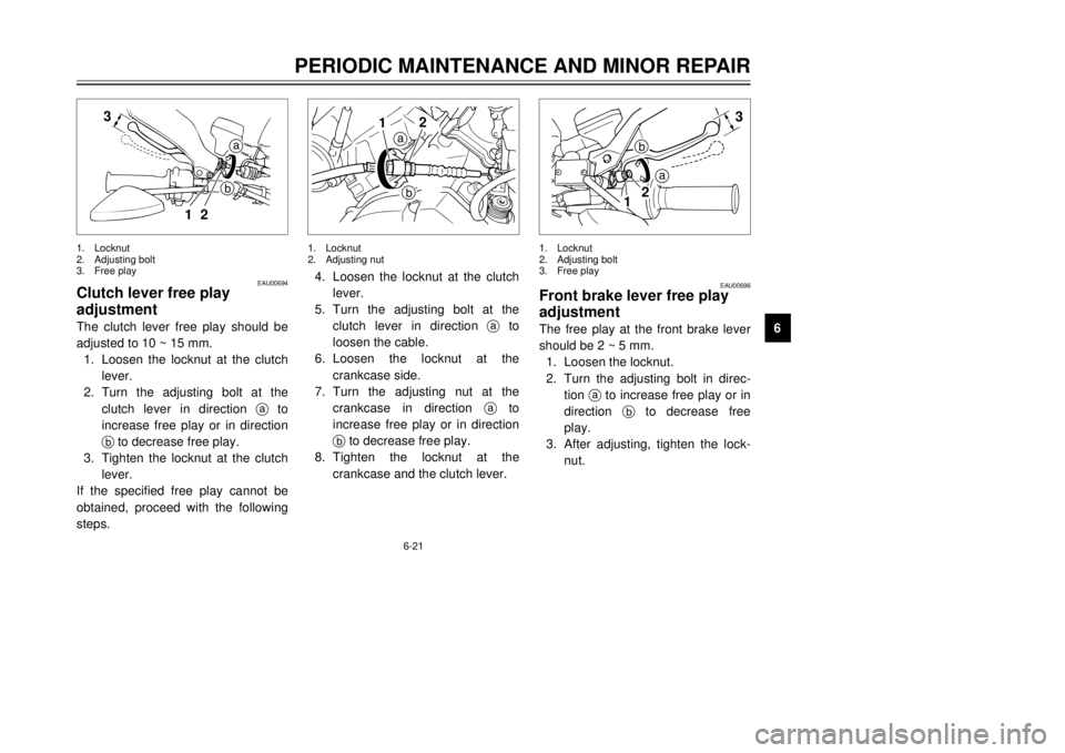
Clutch lever free play
adjustmentThe clutch lever free play should be
adjusted to 10 ~ 15 mm.
1.Loosen the locknut at the clutch
lever.
2.Turn the adjusting bolt at the
clutch lever in direction ato
increase free play or in direction
bto decrease free play.
3.Tighten the locknut at the clutch
lever.
If the specified free play cannot be
obtained, proceed with the following
steps.1.Locknut
2.Adjusting bolt
3.Free play
ab 12
4.Loosen the locknut at the clutch
lever.
5.Turn the adjusting bolt at the
clutch lever in direction ato
loosen the cable.
6.Loosen the locknut at the
crankcase side.
7.Turn the adjusting nut at the
crankcase in direction ato
increase free play or in direction
bto decrease free play.
8.Tighten the locknut at the
crankcase and the clutch lever.1.Locknut
2.Adjusting nut
3
2
1b
a
EAU00696
Front brake lever free play
adjustmentThe free play at the front brake lever
should be 2 ~ 5 mm.
1.Loosen the locknut.
2.Turn the adjusting bolt in direc-
tion ato increase free play or in
direction bto decrease free
play.
3.After adjusting, tighten the lock-
nut.1.Locknut
2.Adjusting bolt
3.Free play
3MB-9-E7 12/27/00 2:52 PM Page 57
Page 59 of 91
6-22
PERIODIC MAINTENANCE AND MINOR REPAIR
1
2
3
4
56
7
8
9
EW000099
w8 8
Check the brake lever free
play. Be sure the brake is
working properly.
8 8
A soft or spongy feeling in the
brake lever can indicate the
presence of air in the brake
system. This air must be
removed by bleeding the brake
system before the motorcycle
is operated. Air in the system
will cause greatly diminished
braking capability and can
result in loss of control and an
accident. Have a Yamaha deal-
er inspect and bleed the sys-
tem if necessary.
a
1
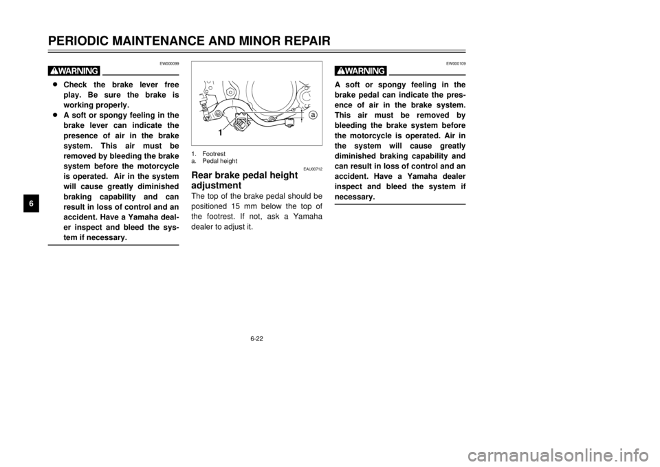
EAU00712
Rear brake pedal height
adjustmentThe top of the brake pedal should be
positioned 15 mm below the top of
the footrest. If not, ask a Yamaha
dealer to adjust it.1.Footrest
a.Pedal height
EW000109
wA soft or spongy feeling in the
brake pedal can indicate the pres-
ence of air in the brake system.
This air must be removed by
bleeding the brake system before
the motorcycle is operated. Air in
the system will cause greatly
diminished braking capability and
can result in loss of control and an
accident. Have a Yamaha dealer
inspect and bleed the system if
necessary.
3MB-9-E7 12/27/00 2:52 PM Page 58
Page 60 of 91
6-23
PERIODIC MAINTENANCE AND MINOR REPAIR
1
2
3
4
56
7
8
9
EAU00713
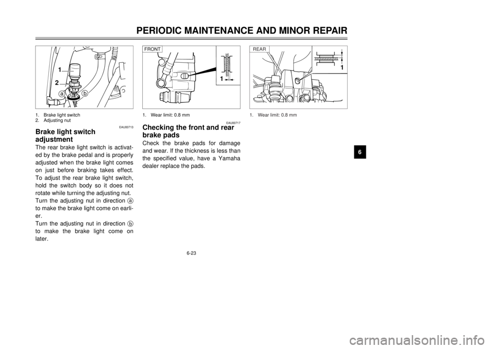
Brake light switch
adjustmentThe rear brake light switch is activat-
ed by the brake pedal and is properly
adjusted when the brake light comes
on just before braking takes effect.
To adjust the rear brake light switch,
hold the switch body so it does not
rotate while turning the adjusting nut.
Turn the adjusting nut in direction a
to make the brake light come on earli-
er.
Turn the adjusting nut in direction b
to make the brake light come on
later.
b
a 1
2
1.Brake light switch
2.Adjusting nut
EAU00717
Checking the front and rear
brake padsCheck the brake pads for damage
and wear. If the thickness is less than
the specified value, have a Yamaha
dealer replace the pads.
1
1.Wear limit: 0.8 mm FRONT
1
1.Wear limit: 0.8 mmREAR
3MB-9-E7 12/27/00 2:52 PM Page 59