engine coolant YAMAHA GIGGLE50 2009 Owners Manual
[x] Cancel search | Manufacturer: YAMAHA, Model Year: 2009, Model line: GIGGLE50, Model: YAMAHA GIGGLE50 2009Pages: 74, PDF Size: 0.9 MB
Page 6 of 74
1
2
3
4
5
6
7
8
9
EAU10210
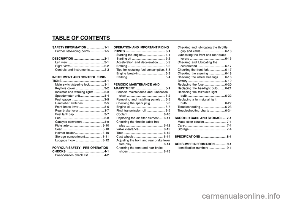
TABLE OF CONTENTSSAFETY INFORMATION .................... 1-1
Further safe-riding points ................ 1-5
DESCRIPTION ................................... 2-1
Left view .......................................... 2-1
Right view ........................................ 2-2
Controls and instruments ................ 2-3
INSTRUMENT AND CONTROL FUNC-
TIONS................................................. 3-1
Main switch/steering lock ................ 3-1
Keyhole cover ................................. 3-2
Indicator and warning lights ............ 3-3
Speedometer unit............................ 3-4
Fuel gauge ...................................... 3-5
Handlebar switches........................ 3-5
Front brake lever ............................. 3-6
Rear brake lever ............................. 3-7
Fuel tank cap ................................... 3-7
Fuel................................................. 3-8
Catalytic converters ......................... 3-9
Kickstarter......................................3-10
Seat...............................................3-10
Helmet holder................................3-10
Storage compartment ....................3-11
Luggage hook...............................3-12
FOR YOUR SAFETY - PRE-OPERATION
CHECKS............................................ 4-1
Pre-operation check list .................. 4-2OPERATION AND IMPORTANT RIDING
POINTS............................................... 5-1
Starting the engine .......................... 5-1
Starting off ....................................... 5-2
Acceleration and deceleration........ 5-2
Braking............................................ 5-2
Tips for reducing fuel consumption . 5-3
Engine break-in............................... 5-3
Parking............................................ 5-4
PERIODIC MAINTENANCE AND
ADJUSTMENT................................... 6-1
Periodic maintenance and lubrication
chart............................................. 6-2
Removing and installing panels ..... 6-5
Checking the spark plug ................. 6-6
Engine oil........................................ 6-7
Final transmission oil ...................... 6-9
Coolant..........................................6-10
Replacing the air filter element .....6-11
Checking the throttle cable free
play............................................6-12
Valve clearance.............................6-12
Tires...............................................6-12
Cast wheels ...................................6-14
Adjusting the front and rear brake lever
free play .....................................6-14
Checking the front and rear brake
shoes.........................................6-15Checking and lubricating the throttle
grip and cable ............................6-16
Lubricating the front and rear brake
levers.........................................6-16
Checking and lubricating the
centerstand................................6-17
Checking the front fork ..................6-17
Checking the steering ...................6-18
Checking the wheel bearings .......6-18
Battery ...........................................6-19
Replacing the fuse ........................6-20
Replacing the headlight bulb ........6-21
Replacing the tail/brake light
bulb............................................6-22
Replacing a turn signal light
bulb............................................6-22
Troubleshooting............................6-23
Troubleshooting charts.................6-24
SCOOTER CARE AND STORAGE .... 7-1
Matte color caution .......................... 7-1
Care................................................. 7-1
Storage............................................ 7-4
SPECIFICATIONS.............................. 8-1
CONSUMER INFORMATION ............. 9-1
Identification numbers..................... 9-1
Page 19 of 74
3-19
1
2
3
4
5
6
7
8
9
EAU1044E
INSTRUMENT AND CONTROL FUNCTIONS
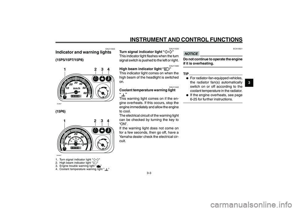
EAU11020
Turn signal indicator light “
5 55 5
5”
This indicator light flashes when the turn
signal switch is pushed to the left or right.
EAU11080
High beam indicator light “
& && &
&”
This indicator light comes on when the
high beam of the headlight is switched
on. Indicator and warning lights
Turn signal indicator light
High beam indicator light
Coolant temperature warning light
EAU11442
Coolant temperature warning light
“
”
This warning light comes on if the en-
gine overheats. If this occurs, stop the
engine immediately and allow the engine
to cool.
The electrical circuit of the warning light
can be checked by turning the key to
“ON”.
If the warning light does not come on
for a few seconds, then go off, have a
Yamaha dealer check the electrical cir-
cuit.
3-3
EAU11003
Indicator and warning lights(15P5/15P7/15P8)ZAUM00**
3
24
1
(15P6)ZAUM00**
0102030
40
50
60
3
24
1
1. Turn signal indicator light "5"
2. High beam indicator light "&"
3. Engine trouble warning light "
"
4. Coolant temperature warning light "
"
ECA10021
NOTICEDo not continue to operate the engine
if it is overheating.TIP●
For radiator-fan-equipped vehicles,
the radiator fan(s) automatically
switch on or off according to the
coolant temperature in the radiator.
●
If the engine overheats, see page
6-25 for further instructions.
Page 30 of 74
4-30
1
2
3
4
5
6
7
8
9
EAU15582
FOR YOUR SAFETY - PRE-OPERATION CHECKS
4-2
EAU15605
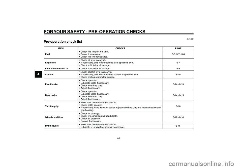
Pre-operation check listPre-operation check list
ITEM CHECKS PAGE
Fuel• Check fuel level in fuel tank.
• Refuel if necessary.
• Check fuel line for leakage.3-5, 3-7
~3-8
Engine oil• Check oil level in engine.
• If necessary, add recommended oil to specified level.
• Check vehicle for oil leakage.6-7
Final transmission oil• Check vehicle for oil leakage. 6-9
Coolant• Check coolant level in reservoir
• If necessary, add recommended coolant to specified level.
• Check cooling system for leakage.6-10
Front brake• Check operation.
• Lubricate cable if necessary.
• Check lever free play.
• Adjust if necessary.6-14
~6-15
Rear brake• Check operation.
• Lubricate cable if necessary.
• Check lever free play.
• Adjust if necessary.6-14~6-15
Throttle grip• Make sure that operation is smooth.
• Check cable free play.
• If necessary, have Yamaha dealer adjust cable free play and lubricate cable and
grip housing.6-16
Wheels and tires• Check for damage.
• Check tire condition and tread depth.
• Check air pressure.
• Correct if necessary.6-12~6-14
Brake levers• Make sure that operation is smooth.
• Lubricate lever pivoting points if necessary.6-16
Page 32 of 74
5-32
1
2
3
4
5
6
7
8
9
EAU15943
OPERATION AND IMPORTANT RIDING POINTS
EAU15943
OPERATION AND IMPORTANT RIDING POINTS
5-1
Starting the engine
EAU15951
Read the Owner’s Manual carefully to
become familiar with all controls. If there
is a control or function you do not un-
derstand, ask your Yamaha dealer.
EWA10271
WARNING
Failure to familiarize yourself with
the controls can lead to loss of con-
trol, which could cause an accident
or injury.
EAU45310
TIP
This model is equipped with a lean angle
sensor to stop the engine in case of a
turnover. To start the engine after a turn-
over, be sure to turn the main switch to
“OFF” and then to “ON”. Failing to do so
will prevent the engine from starting
even though the engine will crank when
pushing the start switch.
EAUT2251
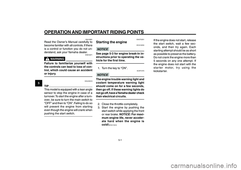
Starting the engine
ECA10250
NOTICESee page 5-3 for engine break-in in-
structions prior to operating the ve-
hicle for the first time.1. Turn the key to “ON”.
ECAT1070
NOTICEThe engine trouble warning light and
coolant temperature warning light
should come on for a few seconds,
then go off. If these warning lights do
not go off, have a Yamaha dealer check
their electrical circuits.2. Close the throttle completely.
3. Start the engine by pushing the
start switch while applying the front
or rear brake.
NOTICE:
For maxi-
mum engine life, never acceler-
ate hard when the engine is
cold!
[ECA11041]
If the engine does not start, release
the start switch, wait a few sec-
onds, and then try again. Each
starting attempt should be as short
as possible to preserve the battery.
Do not crank the engine more than
5 seconds on any one attempt. If
the engine does not start with the
starter motor, try using the
kickstar ter.
Page 38 of 74
6-38
1
2
3
4
5
6
7
8
9
EAU1722A
PERIODIC MAINTENANCE AND ADJUSTMENT
6-3
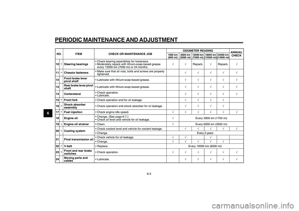
10
*Steering bearings• Check bearing assemblies for looseness.
• Moderately repack with lithium-soap-based grease
every 12000 km (7000 mi) or 24 months.�—�—Repack.�—Repack.�—
11*Chassis fasteners• Make sure that all nuts, bolts and screws are properly
tightened.�—�—�—�— �—
12Front brake lever
pivot shaft• Lubricate with lithium-soap-based grease.�—�—�—�— �—
13Rear brake lever pivot
shaft• Lubricate with lithium-soap-based grease.�—�—�—�— �—
14 Centerstand• Check operation.
• Lubricate.�—�—�—�— �—
15*Front fork• Check operation and for oil leakage.�—�—�—�—
16*Shock absorber
assembly• Check operation and shock absorber for oil leakage.�—�—�—�—
17*Fuel injection• Check engine idle speed.�—�—�—�—�— �—
18 Engine oil• Change. (See page 6-7.)
• Check oil level and vehicle for oil leakage.�—Every 3000 km (1750 mi)
19
*Engine oil strainer•Clean.�—Every 6000 km (3500 mi)
20*Cooling system• Check coolant level and vehicle for coolant leakage.�—�—�—�— �—
• Change. Every 3 years
21 Final transmission oil• Check vehicle for oil leakage.�—�— �—
• Change.�—�—�—�—�—
22*V-belt• Replace. Every 10000 km (6000 mi)
23*Front and rear brake
switches• Check operation.�—�—�—�—�— �—
24Moving parts and
cables• Lubricate.�—�—�—�— �— NO. ITEM CHECK OR MAINTENANCE JOBODOMETER READING
ANNUAL
CHECK
1000 km
(600 mi)6000 km
(3500 mi)12000 km
(7000 mi)18000 km
(10500 mi)24000 km
(14000 mi)
Page 45 of 74
6-45
1
2
3
4
5
6
7
8
9
EAU1722A
PERIODIC MAINTENANCE AND ADJUSTMENT
6-10
torque. WARNING! Make sure that
no foreign material enters the fi-
nal transmission case. Make sure
that no oil gets on the tire or
wheel.
[EWA11311]
Tightening torque:
Final transmission oil filler bolt:
Recommended final transmission oil:
See page 8-1.
Oil quantity:
0.10 L (0.11 US qt, 0.09 Imp.qt)7. Check the final transmission case
for oil leakage. If oil is leaking,
check for the cause.
EAU20070
CoolantThe coolant level should be checked
before each ride. In addition, the cool-
ant must be changed at the intervals
specified in the periodic maintenance
and lubrication chart. Coolant
EAUT1523
To check the coolant level
The coolant level should be checked as
follows before each ride. In addition, the
coolant must be changed at the inter-
vals specified in the periodic mainte-
nance and lubrication chart.
1. Place the vehicle on the
centerstand.TIP
8The coolant level must be checked
on a cold engine since the level
varies with engine temperature.
8Make sure that the vehicle is posi-
tioned straight up when checking
the coolant level. A slight tilt to the
side can result in a false reading.
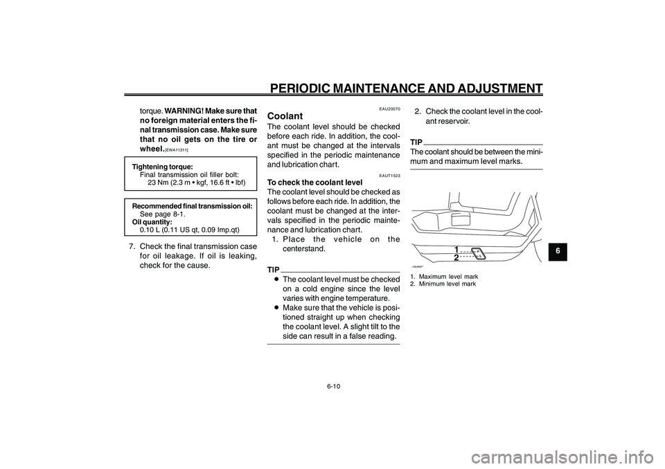
2. Check the coolant level in the cool-
ant reservoir.TIP
The coolant should be between the mini-
mum and maximum level marks.ZAUM00**
12
1. Maximum level mark
2. Minimum level mark
Page 46 of 74
6-46
1
2
3
4
5
6
7
8
9
EAU1722A
PERIODIC MAINTENANCE AND ADJUSTMENT
6-11
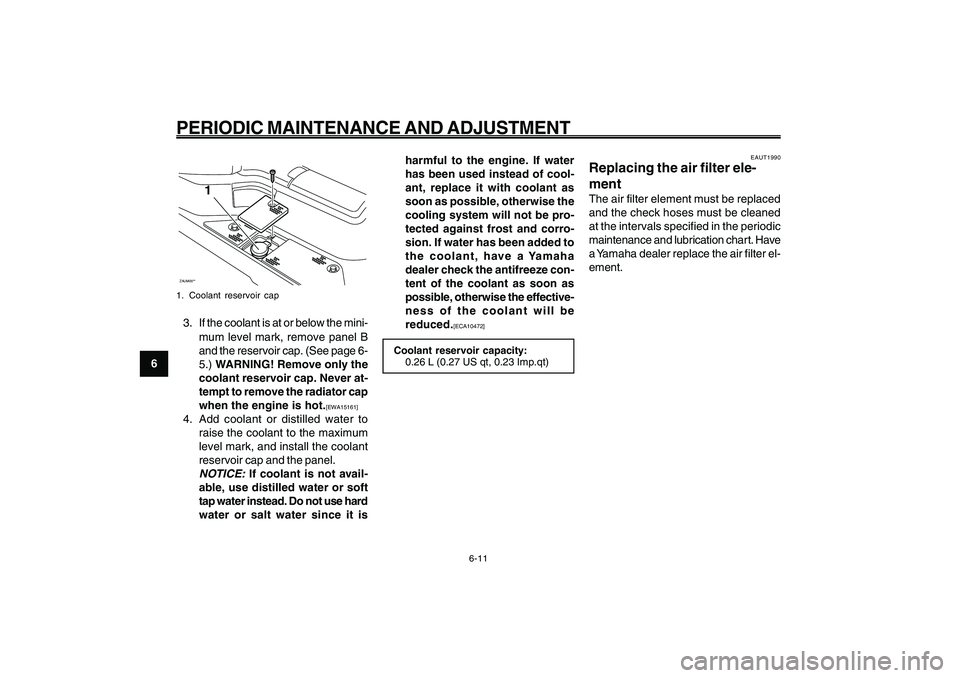
ZAUM00**
1
1. Coolant reservoir cap3. If the coolant is at or below the mini-
mum level mark, remove panel B
and the reservoir cap. (See page 6-
5.) WARNING! Remove only the
coolant reservoir cap. Never at-
tempt to remove the radiator cap
when the engine is hot.
[EWA15161]
4. Add coolant or distilled water to
raise the coolant to the maximum
level mark, and install the coolant
reservoir cap and the panel.
NOTICE:
If coolant is not avail-
able, use distilled water or soft
tap water instead. Do not use hard
water or salt water since it isharmful to the engine. If water
has been used instead of cool-
ant, replace it with coolant as
soon as possible, otherwise the
cooling system will not be pro-
tected against frost and corro-
sion. If water has been added to
the coolant, have a Yamaha
dealer check the antifreeze con-
tent of the coolant as soon as
possible, otherwise the effective-
ness of the coolant will be
reduced.
[ECA10472]
Coolant reservoir capacity:
0.26 L (0.27 US qt, 0.23 Imp.qt)
EAUT1990
Replacing the air filter ele-
mentThe air filter element must be replaced
and the check hoses must be cleaned
at the intervals specified in the periodic
maintenance and lubrication chart. Have
a Yamaha dealer replace the air filter el-
ement. Air filter element, replacing
Page 60 of 74

6-60
1
2
3
4
5
6
7
8
9
EAU1722A
PERIODIC MAINTENANCE AND ADJUSTMENT
6-25
Wait until the
engine has cooled.
Check the coolant level in the
reservoir and radiator.
The coolant level
is OK.The coolant level is low.
Check the cooling system
for leakage.
Have a Yamaha dealer checkand repair the cooling system.Add coolant. (See TIP.)
Start the engine. If the engine overheats again,
have a
Yamaha dealer check
and repair the cooling system.
There is
leakage.
There is
no leakage.
Engine overheating
EWAT1040
WARNING
8 88 8
8Do not remove the radiator cap when the engine and radiator are hot. Scalding hot fluid and steam may be
blown out under pressure, which could cause serious injury. Be sure to wait until the engine has cooled.
8 88 8
8Place a thick rag, like a towel, over the radiator cap, and then slowly rotate the cap counterclockwise to the
detent to allow any residual pressure to escape. When the hissing sound has stopped, press down on the cap
while turning it counterclockwise, and then remove the cap.TIP
If coolant is not available, tap water can be temporarily used instead, provided that it is changed to the recommended coolant
as soon as possible.
Page 66 of 74
8-66
1
2
3
4
5
6
7
8
9
EAU26320
SPECIFICATIONS
8-1
EAU26320
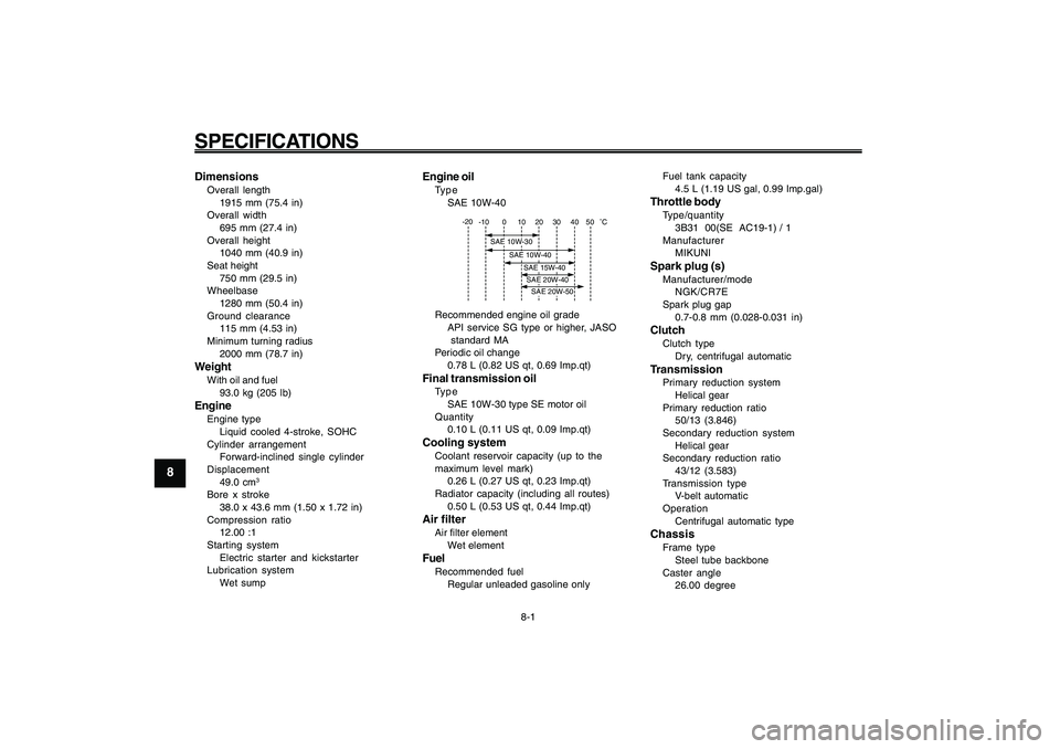
SPECIFICATIONSSpecifications
1915 mm (75.4 in)
Overall width
695 mm (27.4 in)
Overall height
1040 mm (40.9 in)
Seat height
750 mm (29.5 in)
Wheelbase
1280 mm (50.4 in)
Ground clearance
115 mm (4.53 in)
Minimum turning radius
2000 mm (78.7 in)WeightWith oil and fuel
93.0 kg (205 lb)EngineEngine type
Liquid cooled 4-stroke, SOHC
Cylinder arrangement
Forward-inclined single cylinder
Displacement
49.0 cm
3
Bore x stroke
38.0 x 43.6 mm (1.50 x 1.72 in)
Compression ratio
12.00 :1
Starting system
Electric starter and kickstarter
Lubrication system
Wet sump
Engine oilType
SAE 10W-40
-10 0 10 20 30
40 -20
50
�C
SAE 10W-30
SAE 10W-40
SAE 15W-40SAE 20W-40SAE 20W-50
Recommended engine oil grade
API service SG type or higher, JASO
standard MA
Periodic oil change
0.78 L (0.82 US qt, 0.69 Imp.qt)Final transmission oilType
SAE 10W-30 type SE motor oil
Quantity
0.10 L (0.11 US qt, 0.09 Imp.qt)Cooling systemCoolant reservoir capacity (up to the
maximum level mark)
0.26 L (0.27 US qt, 0.23 Imp.qt)
Radiator capacity (including all routes)
0.50 L (0.53 US qt, 0.44 Imp.qt)Air filterAir filter element
Wet elementFuelRecommended fuel
Regular unleaded gasoline onlyFuel tank capacity
4.5 L (1.19 US gal, 0.99 Imp.gal)
Throttle bodyType/quantity
3B31 00(SE AC19-1) / 1
Manufacturer
MIKUNISpark plug (s)Manufacturer/mode
NGK/CR7E
Spark plug gap
0.7-0.8 mm (0.028-0.031 in)ClutchClutch type
Dry, centrifugal automaticTransmissionPrimary reduction system
Helical gear
Primary reduction ratio
50/13 (3.846)
Secondary reduction system
Helical gear
Secondary reduction ratio
43/12 (3.583)
Transmission type
V-belt automatic
Operation
Centrifugal automatic typeChassisFrame type
Steel tube backbone
Caster angle
26.00 degree
Page 67 of 74

8-67
1
2
3
4
5
6
7
8
9
EAU26320
SPECIFICATIONS
8-2 Trail
84.0 mm (3.31 in)
Front tireType
Tubeless
Size
120/90-10 57J
Manufacturer/model
CHENG SHIN / C-6022Rear tireType
Tubeless
Size
120/90-10 57J
Manufacturer/model
CHENG SHIN / C-6022LoadingMaximum load
177 kg (390 lb)Tire air pressure (measured on cold
tires)Front
175 kPa (1.75 kgf/cm
2, 25 psi, 1.75 bar)
Rear
175 kPa (1.75 kgf/cm2, 25 psi, 1.75 bar)
Front wheelWheel type
Cast wheel
Rim size
10 x 3.00Rear wheelWheel type
Cast wheelRim size
10 x 3.00
Front brakeType
Drum brake
Operation
Right hand operationRear brakeType
Drum brake
Operation
Left hand operationFront suspensionType
Telescopic fork
Spring/shock absorber type
Coil spring
Wheel travel
65.0 mm (2.56 in)Rear suspensionType
Unit swing
Spring/shock absorber type
Coil spring
Wheel travel
56.0 mm (2.20 in)Electrical systemIgnition system
TCI
Charging system
AC magnetoBatteryModel
GTX5L-BSVoltage, capacity
12 V, 4.0 Ah
HeadlightBulb type
Halogen bulbBulb voltage, wattage x quantityHeadlight
12 V, 35 W/35.0 W x 1
Tail/brake light
12 V, 5.0 W/21.0 W x 1
Front turn signal light
12 V, 10.0 W x 2
Rear turn signal light
12 V, 10.0 W x 2
Meter lighting
12 V, 1.7 W x 1
High beam indicator light
12 V, 1.7 W x 1
Turn signal indicator light
14 V, 3.0 W x 1
Coolant temperature warning light
12 V, 1.7 W x 1
Engine trouble warning light
12 V, 1.7 W x 1FusesMain fuse
15.0 A