lock YAMAHA GIGGLE50 2009 Owners Manual
[x] Cancel search | Manufacturer: YAMAHA, Model Year: 2009, Model line: GIGGLE50, Model: YAMAHA GIGGLE50 2009Pages: 74, PDF Size: 0.9 MB
Page 6 of 74
1
2
3
4
5
6
7
8
9
EAU10210
TABLE OF CONTENTSSAFETY INFORMATION .................... 1-1
Further safe-riding points ................ 1-5
DESCRIPTION ................................... 2-1
Left view .......................................... 2-1
Right view ........................................ 2-2
Controls and instruments ................ 2-3
INSTRUMENT AND CONTROL FUNC-
TIONS................................................. 3-1
Main switch/steering lock ................ 3-1
Keyhole cover ................................. 3-2
Indicator and warning lights ............ 3-3
Speedometer unit............................ 3-4
Fuel gauge ...................................... 3-5
Handlebar switches........................ 3-5
Front brake lever ............................. 3-6
Rear brake lever ............................. 3-7
Fuel tank cap ................................... 3-7
Fuel................................................. 3-8
Catalytic converters ......................... 3-9
Kickstarter......................................3-10
Seat...............................................3-10
Helmet holder................................3-10
Storage compartment ....................3-11
Luggage hook...............................3-12
FOR YOUR SAFETY - PRE-OPERATION
CHECKS............................................ 4-1
Pre-operation check list .................. 4-2OPERATION AND IMPORTANT RIDING
POINTS............................................... 5-1
Starting the engine .......................... 5-1
Starting off ....................................... 5-2
Acceleration and deceleration........ 5-2
Braking............................................ 5-2
Tips for reducing fuel consumption . 5-3
Engine break-in............................... 5-3
Parking............................................ 5-4
PERIODIC MAINTENANCE AND
ADJUSTMENT................................... 6-1
Periodic maintenance and lubrication
chart............................................. 6-2
Removing and installing panels ..... 6-5
Checking the spark plug ................. 6-6
Engine oil........................................ 6-7
Final transmission oil ...................... 6-9
Coolant..........................................6-10
Replacing the air filter element .....6-11
Checking the throttle cable free
play............................................6-12
Valve clearance.............................6-12
Tires...............................................6-12
Cast wheels ...................................6-14
Adjusting the front and rear brake lever
free play .....................................6-14
Checking the front and rear brake
shoes.........................................6-15Checking and lubricating the throttle
grip and cable ............................6-16
Lubricating the front and rear brake
levers.........................................6-16
Checking and lubricating the
centerstand................................6-17
Checking the front fork ..................6-17
Checking the steering ...................6-18
Checking the wheel bearings .......6-18
Battery ...........................................6-19
Replacing the fuse ........................6-20
Replacing the headlight bulb ........6-21
Replacing the tail/brake light
bulb............................................6-22
Replacing a turn signal light
bulb............................................6-22
Troubleshooting............................6-23
Troubleshooting charts.................6-24
SCOOTER CARE AND STORAGE .... 7-1
Matte color caution .......................... 7-1
Care................................................. 7-1
Storage............................................ 7-4
SPECIFICATIONS.............................. 8-1
CONSUMER INFORMATION ............. 9-1
Identification numbers..................... 9-1
Page 16 of 74
2-16
1
2
3
4
5
6
7
8
9
EAU10401
DESCRIPTION
2-3
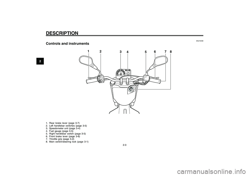
EAU10430
Controls and instruments1. Rear brake lever (page 3-7)
2. Left handlebar switches (page 3-5)
3. Speedometer unit (page 3-4)
4. Fuel gauge (page 3-5)
5. Right handlebar switch (page 3-5)
6. Front brake lever (page 3-6)
7. Throttle grip (page 5-2)
8. Main switch/steering lock (page 3-1)
1
2
3
4
5
6
7
8
Page 17 of 74
3-17
1
2
3
4
5
6
7
8
9
EAU1044E
INSTRUMENT AND CONTROL FUNCTIONS
3-1
Main switch/steering lock
EAU10460
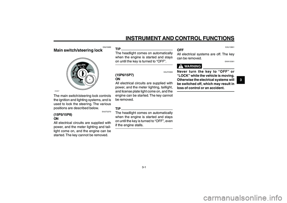
Main switch/steering lockZAUM00**The main switch/steering lock controls
the ignition and lighting systems, and is
used to lock the steering. The various
positions are described below.
EAUT2270
(15P5/15P8)
ON
All electrical circuits are supplied with
power, and the meter lighting and tail-
light come on, and the engine can be
started. The key cannot be removed.
EAUT2060
(15P6/15P7)
ON
All electrical circuits are supplied with
power, and the meter lighting, taillight,
and license plate light come on, and the
engine can be started. The key cannot
be removed.TIP
The headlight comes on automatically
when the engine is started and stays
on until the key is turned to “OFF”, even
if the engine stalls.
EAU10661
OFF
All electrical systems are off. The key
can be removed.
EWA10061
WARNING
Never turn the key to “OFF” or
“LOCK” while the vehicle is moving.
Otherwise the electrical systems will
be switched off, which may result in
loss of control or an accident.
EAU1044E
INSTRUMENT AND CONTROL FUNCTIONS
TIP
The headlight comes on automatically
when the engine is started and stays
on until the key is turned to “OFF”.
Page 18 of 74
3-18
1
2
3
4
5
6
7
8
9
EAU1044E
INSTRUMENT AND CONTROL FUNCTIONS
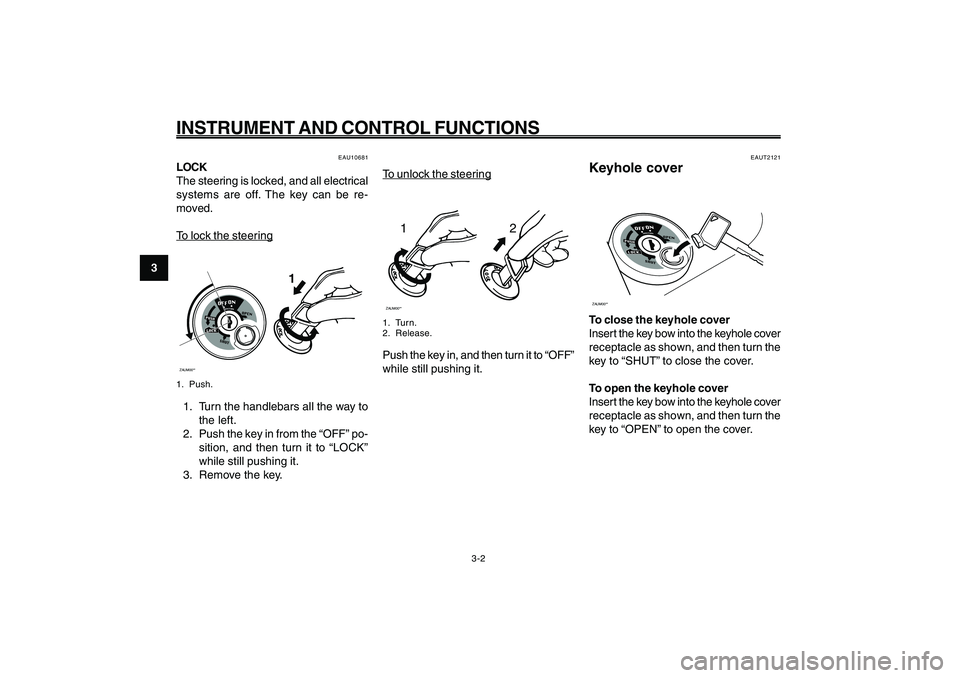
To unloc
k the steer
ing
12
ZAUM00**1. Turn.
2. Release.Push the key in, and then turn it to “OFF”
while still pushing it.
EAUT2121
Keyhole coverZAUM00**To close the keyhole cover
Insert the key bow into the keyhole cover
receptacle as shown, and then turn the
key to “SHUT” to close the cover.
To open the keyhole cover
Insert the key bow into the keyhole cover
receptacle as shown, and then turn the
key to “OPEN” to open the cover. Keyhole cover
3-2
EAU10681
LOCK
The steering is locked, and all electrical
systems are off. The key can be re-
moved.To loc
k the steer
ing
ZAUM00**
1
1. Push.1. Turn the handlebars all the way to
the left.
2. Push the key in from the “OFF” po-
sition, and then turn it to “LOCK”
while still pushing it.
3. Remove the key.
Page 23 of 74
3-23
1
2
3
4
5
6
7
8
9
EAU1044E
INSTRUMENT AND CONTROL FUNCTIONS
3-7
Brake lever, rear
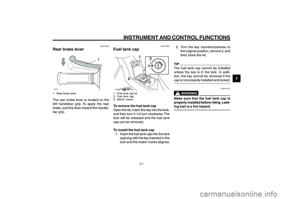
Fuel tank cap
EAUT2281
Fuel tank capZAUM00**
3
1
2
1. Fuel tank cap lid
2. Fuel tank cap
3. Match marksTo remove the fuel tank cap
Open the lid, insert the key into the lock,
and then turn it 1/4 turn clockwise. The
lock will be released and the fuel tank
cap can be removed.
To install the fuel tank cap
1. Inser t the fuel tank cap into the tank
opening with the key inserted in the
lock and the match marks aligned.2. Turn the key counterclockwise to
the original position, remove it, and
then close the lid.
TIP
The fuel tank cap cannot be installed
unless the key is in the lock. In addi-
tion, the key cannot be removed if the
cap is not properly installed and locked.
EWA10131
WARNING
Make sure that the fuel tank cap is
properly installed before riding. Leak-
ing fuel is a fire hazard.
EAU12950
Rear brake lever
1
ZAUM00**1. Rear brake leverThe rear brake lever is located on the
left handlebar grip. To apply the rear
brake, pull this lever toward the handle-
bar grip.
Page 26 of 74
3-26
1
2
3
4
5
6
7
8
9
EAU1044E
INSTRUMENT AND CONTROL FUNCTIONS
3-10
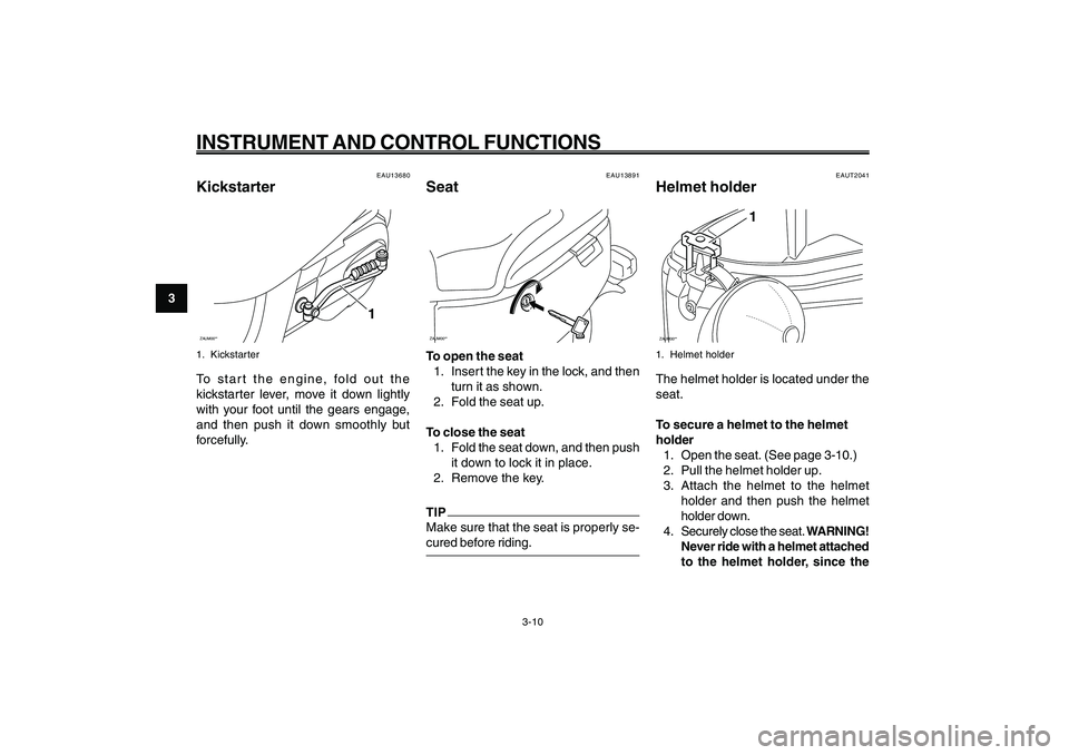
Kickstarter
Seat
Helmet holder
EAU13891
SeatZAUM00**To open the seat
1. Insert the key in the lock, and then
turn it as shown.
2. Fold the seat up.
To close the seat
1. Fold the seat down, and then push
it down to lock it in place.
2. Remove the key.TIP
Make sure that the seat is properly se-
cured before riding.
EAUT2041
Helmet holderZAUM00**
1
1. Helmet holderThe helmet holder is located under the
seat.
To secure a helmet to the helmet
holder
1. Open the seat. (See page 3-10.)
2. Pull the helmet holder up.
3. Attach the helmet to the helmet
holder and then push the helmet
holder down.
4. Securely close the seat. WARNING!
Never ride with a helmet attached
to the helmet holder, since the
EAU13680
KickstarterZAUM00**
1
1. KickstarterTo start the engine, fold out the
kickstarter lever, move it down lightly
with your foot until the gears engage,
and then push it down smoothly but
forcefully.
Page 56 of 74
6-56
1
2
3
4
5
6
7
8
9
EAU1722A
PERIODIC MAINTENANCE AND ADJUSTMENT
6-21
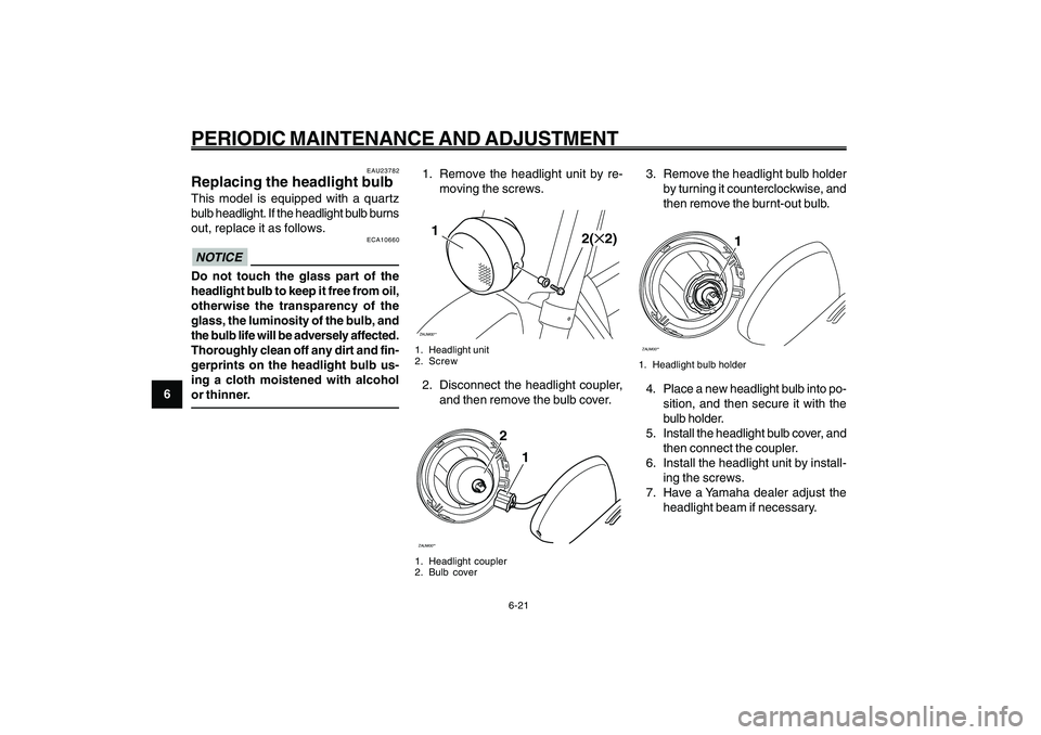
1. Remove the headlight unit by re-
moving the screws.ZAUM00**1
2(✕2)
1. Headlight unit
2. Screw2. Disconnect the headlight coupler,
and then remove the bulb cover.ZAUM00**
2
1
1. Headlight coupler
2. Bulb cover
3. Remove the headlight bulb holder
by turning it counterclockwise, and
then remove the burnt-out bulb.ZAUM00**
1
1. Headlight bulb holder4. Place a new headlight bulb into po-
sition, and then secure it with the
bulb holder.
5. Install the headlight bulb cover, and
then connect the coupler.
6. Install the headlight unit by install-
ing the screws.
7. Have a Yamaha dealer adjust the
headlight beam if necessary. Headlight bulb, replacing
EAU23782
Replacing the headlight bulbThis model is equipped with a quartz
bulb headlight. If the headlight bulb burns
out, replace it as follows.
ECA10660
NOTICEDo not touch the glass part of the
headlight bulb to keep it free from oil,
otherwise the transparency of the
glass, the luminosity of the bulb, and
the bulb life will be adversely affected.
Thoroughly clean off any dirt and fin-
gerprints on the headlight bulb us-
ing a cloth moistened with alcohol
or thinner.
Page 57 of 74
6-57
1
2
3
4
5
6
7
8
9
EAU1722A
PERIODIC MAINTENANCE AND ADJUSTMENT
6-22
Tail/brake light bulb, replacing
Turn signal light bulb, replacing
EAU24204
Replacing a turn signal light
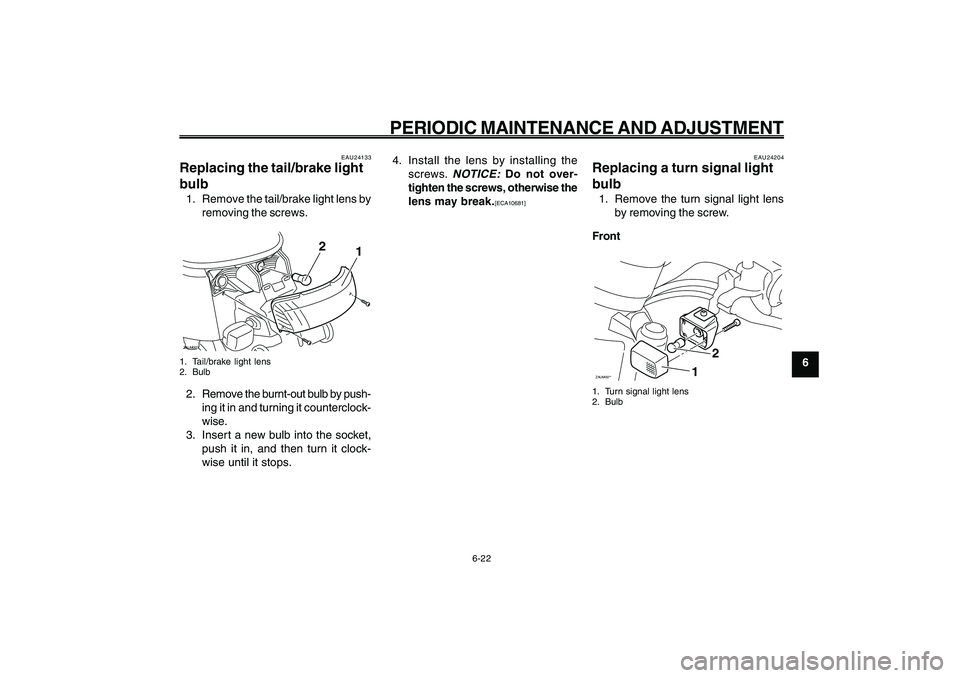
bulb1. Remove the turn signal light lens
by removing the screw.
FrontZAUM00**
2
1
1. Turn signal light lens
2. Bulb
EAU24133
Replacing the tail/brake light
bulb1. Remove the tail/brake light lens by
removing the screws.ZAUM00**
1
2
1. Tail/brake light lens
2. Bulb2. Remove the burnt-out bulb by push-
ing it in and turning it counterclock-
wise.
3. Insert a new bulb into the socket,
push it in, and then turn it clock-
wise until it stops.4. Install the lens by installing the
screws.
NOTICE:
Do not over-
tighten the screws, otherwise the
lens may break.[ECA10681]
Page 58 of 74
6-58
1
2
3
4
5
6
7
8
9
EAU1722A
PERIODIC MAINTENANCE AND ADJUSTMENT
6-23
EWA15141
WARNING
When checking the fuel system, do
not smoke, and make sure there are
no open flames or sparks in the area,
including pilot lights from water heat-
ers or furnaces. Gasoline or gasoline
vapors can ignite or explode, caus-
ing severe injury or property damage.
EAU25881
TroubleshootingAlthough Yamaha scooters receive a
thorough inspection before shipment
from the factory, trouble may occur dur-
ing operation. Any problem in the fuel,
compression, or ignition systems, for
example, can cause poor starting and
loss of power.
The following troubleshooting charts rep-
resent quick and easy procedures for
checking these vital systems yourself.
However, should your scooter require any
repair, take it to a Yamaha dealer, whose
skilled technicians have the necessary
tools, experience, and know-how to ser-
vice the scooter properly.
Use only genuine Yamaha replacement
parts. Imitation par ts may look like
Yamaha parts, but they are often infe-
rior, have a shorter service life and can
lead to expensive repair bills. Troubleshooting
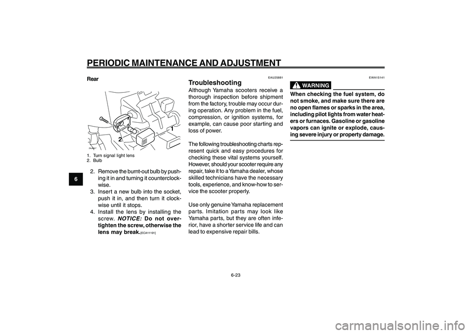
Rear
ZAUM00**
1
2
1. Turn signal light lens
2. Bulb2. Remove the burnt-out bulb by push-
ing it in and turning it counterclock-
wise.
3. Insert a new bulb into the socket,
push it in, and then turn it clock-
wise until it stops.
4. Install the lens by installing the
screw.
NOTICE:
Do not over-
tighten the screw, otherwise the
lens may break.[ECA11191]
Page 60 of 74

6-60
1
2
3
4
5
6
7
8
9
EAU1722A
PERIODIC MAINTENANCE AND ADJUSTMENT
6-25
Wait until the
engine has cooled.
Check the coolant level in the
reservoir and radiator.
The coolant level
is OK.The coolant level is low.
Check the cooling system
for leakage.
Have a Yamaha dealer checkand repair the cooling system.Add coolant. (See TIP.)
Start the engine. If the engine overheats again,
have a
Yamaha dealer check
and repair the cooling system.
There is
leakage.
There is
no leakage.
Engine overheating
EWAT1040
WARNING
8 88 8
8Do not remove the radiator cap when the engine and radiator are hot. Scalding hot fluid and steam may be
blown out under pressure, which could cause serious injury. Be sure to wait until the engine has cooled.
8 88 8
8Place a thick rag, like a towel, over the radiator cap, and then slowly rotate the cap counterclockwise to the
detent to allow any residual pressure to escape. When the hissing sound has stopped, press down on the cap
while turning it counterclockwise, and then remove the cap.TIP
If coolant is not available, tap water can be temporarily used instead, provided that it is changed to the recommended coolant
as soon as possible.