YAMAHA NMAX 2015 Repair Manual
Manufacturer: YAMAHA, Model Year: 2015, Model line: NMAX, Model: YAMAHA NMAX 2015Pages: 90, PDF Size: 3.56 MB
Page 61 of 90
Periodic maintenance an d a djustment
6-21
6
EAU21963
Cast wheelsTo maximize the performance, durabil-
ity, and safe operation of your vehicle,
note the following points regarding the
specified wheels.
The wheel rims should be
checked for cracks, bends, warp-
age or other damage before each
ride. If any damage is found, have
a Yamaha dealer replace the
wheel. Do not attempt even the
smallest repair to the wheel. A de-
formed or cracked wheel must be
replaced.
The wheel should be balanced
whenever either the tire or wheel
has been changed or replaced. An
unbalanced wheel can result in
poor performance, adverse han-
dling characteristics, and a short-
ened tire life.
EAU50861
Checkin g the front an d rear
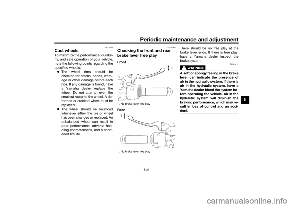
b rake lever free playFront
Rear There should be no free play at the
brake lever ends. If there is free play,
have a Yamaha dealer inspect the
brake system.
WARNING
EWA14212
A soft or spon
gy feelin g in the b rake
lever can in dicate the presence of
air in the hy draulic system. If there is
air in the hy draulic system, have a
Yamaha dealer blee d the system be-
fore operatin g the vehicle. Air in the
hy draulic system will diminish the
b rakin g performance, which may re-
sult in loss of control an d an acci-
d ent.
1. No brake lever free play
1. No brake lever free play
1
1
U2DSE0E0.book Page 21 Thursday, March 19, 2015 10:34 AM
Page 62 of 90
Periodic maintenance an d a djustment
6-22
6
EAU22393
Checkin g the front an d rear
b rake pa dsThe front and rear brake pads must be
checked for wear at the intervals spec-
ified in the periodic maintenance and
lubrication chart.
EAU22432
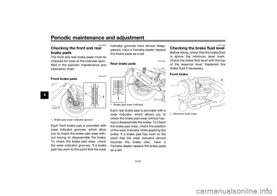
Front brake pa ds
Each front brake pad is provided with
wear indicator grooves, which allow
you to check the brake pad wear with-
out having to disassemble the brake.
To check the brake pad wear, check
the wear indicator grooves. If a brake
pad has worn to the point that the wear indicator grooves have almost disap-
peared, have a Yamaha dealer replace
the brake pads as a set.
EAU22461
Rear
brake pad s
Each rear brake pad is provided with a
wear indicator, which allows you to
check the brake pad wear without hav-
ing to disassemble the brake. To check
the brake pad wear, check the position
of the wear indicator while applying the
brake. If a brake pad has worn to the
point that the wear indicator almost
touches the brake disc, have a
Yamaha dealer replace the brake pads as a set.
EAU22582
Checkin g the brake flui d levelBefore riding, check that the brake fluid
is above the minimum level mark.
Check the brake fluid level with the top
of the reservoir level. Replenish the
brake fluid if necessary.
Front brake
1. Brake pad wear indicator groove
1
1
1. Brake pad wear indicator
1
1. Minimum level mark
1
U2DSE0E0.book Page 22 Thursday, March 19, 2015 10:34 AM
Page 63 of 90
Periodic maintenance an d a djustment
6-23
6
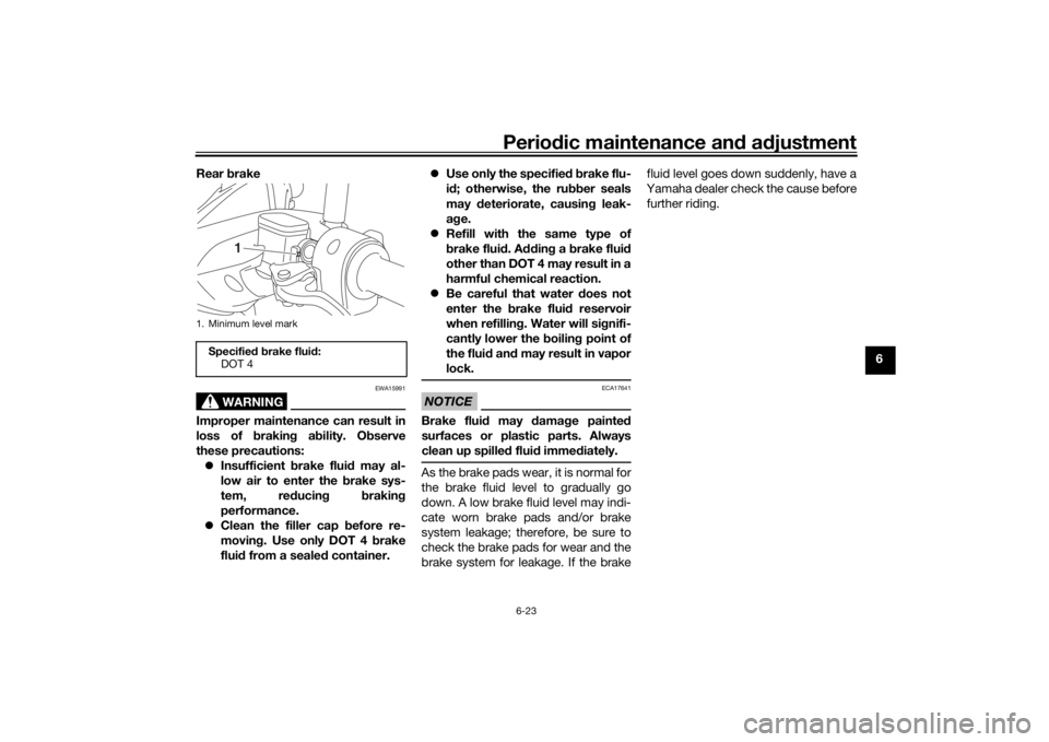
Rear
brake
WARNING
EWA15991
Improper maintenance can result in
loss of b raking a bility. O bserve
these precautions: Insufficient brake flui d may al-
low air to enter the brake sys-
tem, re ducin g brakin g
performance.
Clean the filler cap before re-
movin g. Use only DOT 4 brake
flui d from a seale d container.
Use only the specified b rake flu-
i d ; otherwise, the ru bber seals
may deteriorate, causin g leak-
a g e.
Refill with the same type of
brake flui d. A dding a brake fluid
other than DOT 4 may result in a
harmful chemical reaction.
Be careful that water d oes not
enter the brake flui d reservoir
when refillin g. Water will si gnifi-
cantly lower the boilin g point of
the flui d an d may result in vapor
lock.
NOTICE
ECA17641
Brake flui d may d amage painte d
surfaces or plastic parts. Always
clean up spilled fluid imme diately.As the brake pads wear, it is normal for
the brake fluid level to gradually go
down. A low brake fluid level may indi-
cate worn brake pads and/or brake
system leakage; therefore, be sure to
check the brake pads for wear and the
brake system for leakage. If the brake fluid level goes down suddenly, have a
Yamaha dealer check the cause before
further riding.
1. Minimum level markSpecifie
d b rake flui d:
DOT 4
1
U2DSE0E0.book Page 23 Thursday, March 19, 2015 10:34 AM
Page 64 of 90

Periodic maintenance an d a djustment
6-24
6
EAU22733
Chan gin g the brake flui dHave a Yamaha dealer change the
brake fluid at the intervals specified in
the periodic maintenance and lubrica-
tion chart. In addition, have the oil seals
of the master cylinders and calipers as
well as the brake hoses replaced at the
intervals listed below or whenever they
are damaged or leaking.
Oil seals: Replace every two
years.
Brake hoses: Replace every four
years.
EAUU0311
Checkin g the V- beltThe V-belt must be checked and re-
placed by a Yamaha dealer at the inter-
vals specified in the periodic
maintenance and lubrication chart.
EAU23098
Checkin g an d lu bricatin g the
cab lesThe operation of all control cables and
the condition of the cables should be
checked before each ride, and the ca-
bles and cable ends should be lubri-
cated if necessary. If a cable is
damaged or does not move smoothly,
have a Yamaha dealer check or re-
place it. WARNING! Dama ge to the
outer housin g of cab les may result
in internal rustin g an d cause inter-
ference with cab le movement. Re-
place damag ed cab les as soon as
possi ble to prevent unsafe con di-
tions.
[EWA10712]
Recommen ded lu bricant:
Yamaha cable lubricant or other
suitable cable lubricant
U2DSE0E0.book Page 24 Thursday, March 19, 2015 10:34 AM
Page 65 of 90
Periodic maintenance an d a djustment
6-25
6
EAU49921
Checkin g an d lu bricatin g the
throttle grip an d ca bleThe operation of the throttle grip
should be checked before each ride. In
addition, the cable should be lubricat-
ed by a Yamaha dealer at the intervals
specified in the periodic maintenance
chart.
EAU23173
Lu bricatin g the front an d rear
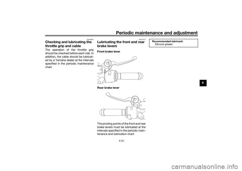
b rake leversFront brake lever
Rear brake lever
The pivoting points of the front and rear
brake levers must be lubricated at the
intervals specified in the periodic main-
tenance and lubrication chart.
Recommen ded lu bricant:
Silicone grease
U2DSE0E0.book Page 25 Thursday, March 19, 2015 10:34 AM
Page 66 of 90
Periodic maintenance an d a djustment
6-26
6
EAU23215
Checkin g an d lu bricatin g the
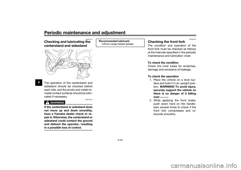
centerstan d an d sid estan dThe operation of the centerstand and
sidestand should be checked before
each ride, and the pivots and metal-to-
metal contact surfaces should be lubri-
cated if necessary.
WARNING
EWA10742
If the centerstan d or si destan d d oes
not move up an d d own smoothly,
have a Yamaha d ealer check or re-
pair it. Otherwise, the centerstan d or
si destan d coul d contact the groun d
an d d istract the operator, resultin g
in a possi ble loss of control.
EAU23273
Checkin g the front forkThe condition and operation of the
front fork must be checked as follows
at the intervals specified in the periodic
maintenance and lubrication chart.
To check the con dition
Check the inner tubes for scratches,
damage and excessive oil leakage.
To check the operation 1. Place the vehicle on a level sur- face and hold it in an upright posi-
tion. WARNING! To avoi d injury,
securely support the vehicle so
there is no dan ger of it fallin g
over.
[EWA10752]
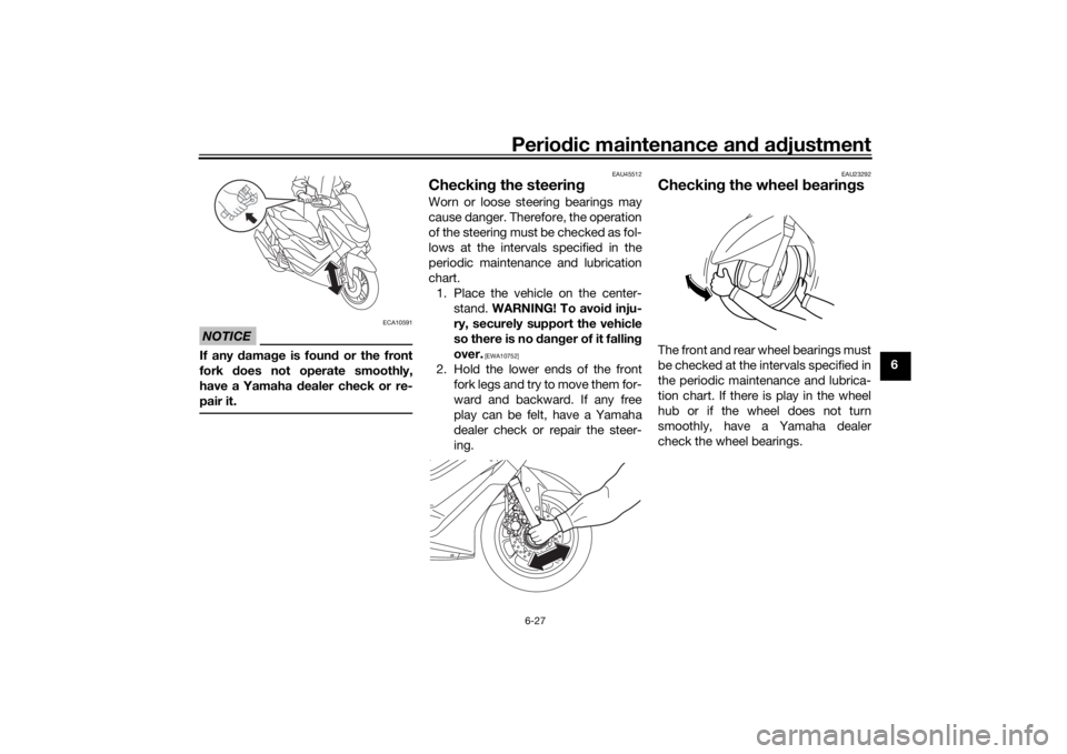
2. While applying the front brake, push down hard on the handle-
bars several times to check if the
front fork compresses and re-
bounds smoothly.
Recommen ded lu bricant:
Lithium-soap-based grease
U2DSE0E0.book Page 26 Thursday, March 19, 2015 10:34 AM
Page 67 of 90
Periodic maintenance an d a djustment
6-27
6
NOTICE
ECA10591
If any damag e is foun d or the front
fork does not operate smoothly,
have a Yamaha d ealer check or re-
pair it.
EAU45512
Checkin g the steerin gWorn or loose steering bearings may
cause danger. Therefore, the operation
of the steering must be checked as fol-
lows at the intervals specified in the
periodic maintenance and lubrication
chart.
1. Place the vehicle on the center- stand. WARNING! To avoi d inju-
ry, securely support the vehicle
so there is no dan ger of it fallin g
over.
[EWA10752]
2. Hold the lower ends of the front fork legs and try to move them for-
ward and backward. If any free
play can be felt, have a Yamaha
dealer check or repair the steer-
ing.
EAU23292
Checkin g the wheel bearin gsThe front and rear wheel bearings must
be checked at the intervals specified in
the periodic maintenance and lubrica-
tion chart. If there is play in the wheel
hub or if the wheel does not turn
smoothly, have a Yamaha dealer
check the wheel bearings.
U2DSE0E0.book Page 27 Thursday, March 19, 2015 10:34 AM
Page 68 of 90
Periodic maintenance an d a djustment
6-28
6
EAU50291
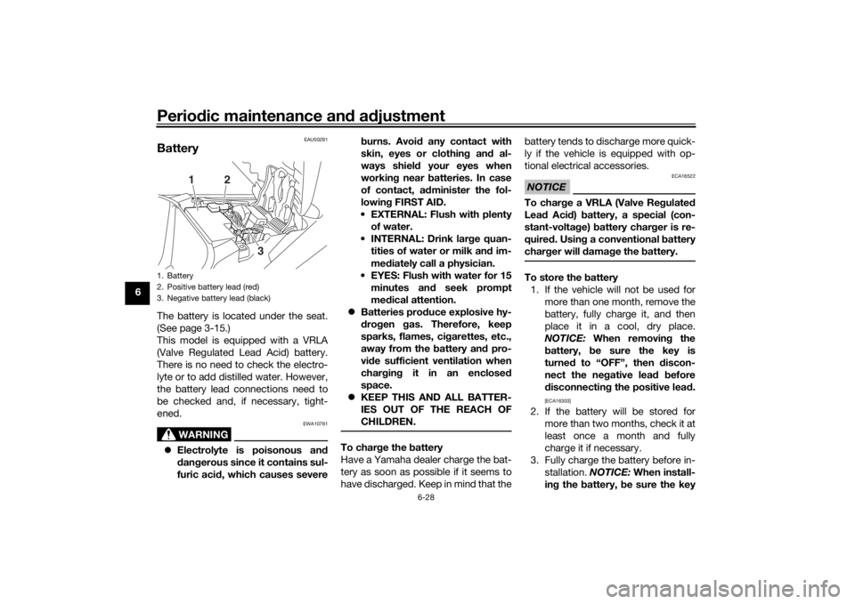
BatteryThe battery is located under the seat.
(See page 3-15.)
This model is equipped with a VRLA
(Valve Regulated Lead Acid) battery.
There is no need to check the electro-
lyte or to add distilled water. However,
the battery lead connections need to
be checked and, if necessary, tight-
ened.
WARNING
EWA10761
Electrolyte is poisonous an d
d an gerous since it contains sul-
furic aci d, which causes severe b
urns. Avoi d any contact with
skin, eyes or clothin g an d al-
ways shiel d your eyes when
workin g near b atteries. In case
of contact, a dminister the fol-
lowin g FIRST AID.
EXTERNAL: Flush with plenty of water.
INTERNAL: Drink lar ge quan-
tities of water or milk and im-
me diately call a physician.
EYES: Flush with water for 15 minutes an d seek prompt
me dical attention.
Batteries pro duce explosive hy-
d ro gen gas. Therefore, keep
sparks, flames, ci garettes, etc.,
away from the battery an d pro-
vi de sufficient ventilation when
char gin g it in an enclose d
space.
KEEP THIS AND ALL BATTER-
IES OUT OF THE REACH OF
CHILDREN.
To char ge the battery
Have a Yamaha dealer charge the bat-
tery as soon as possible if it seems to
have discharged. Keep in mind that the battery tends to discharge more quick-
ly if the vehicle is equipped with op-
tional electrical accessories.
NOTICE
ECA16522
To char
ge a VRLA (Valve Re gulate d
Lea d Aci d) battery, a special (con-
stant-volta ge) battery char ger is re-
quire d. Usin g a conventional b attery
char ger will damag e the b attery.To store the battery
1. If the vehicle will not be used for more than one month, remove the
battery, fully charge it, and then
place it in a cool, dry place.
NOTICE: When removin g the
b attery, be sure the key is
turne d to “OFF”, then d iscon-
nect the neg ative lead b efore
d isconnectin g the positive lea d.
[ECA16303]
2. If the battery will be stored for
more than two months, check it at
least once a month and fully
charge it if necessary.
3. Fully charge the battery before in- stallation. NOTICE: When install-
in g the b attery, be sure the key
1. Battery
2. Positive battery lead (red)
3. Negative battery lead (black)
1
2
3
U2DSE0E0.book Page 28 Thursday, March 19, 2015 10:34 AM
Page 69 of 90
![YAMAHA NMAX 2015 Repair Manual Periodic maintenance an d a djustment
6-29
6
is turne
d to “OFF”, then connect
the positive lea d before con-
nectin g the ne gative lead .
[ECA16841]
4. After installation, make sure that
the b YAMAHA NMAX 2015 Repair Manual Periodic maintenance an d a djustment
6-29
6
is turne
d to “OFF”, then connect
the positive lea d before con-
nectin g the ne gative lead .
[ECA16841]
4. After installation, make sure that
the b](/img/51/51058/w960_51058-68.png)
Periodic maintenance an d a djustment
6-29
6
is turne
d to “OFF”, then connect
the positive lea d before con-
nectin g the ne gative lead .
[ECA16841]
4. After installation, make sure that
the battery leads are properly con-
nected to the battery terminals.NOTICE
ECA16531
Always keep the b attery charged .
Storin g a dischar ged battery can
cause permanent battery damag e.
EAU66790
Replacin g the fusesThe fuse boxes, which contain the fus-
es for the individual circuits, are locat-
ed under the seat. (See page 3-15.)
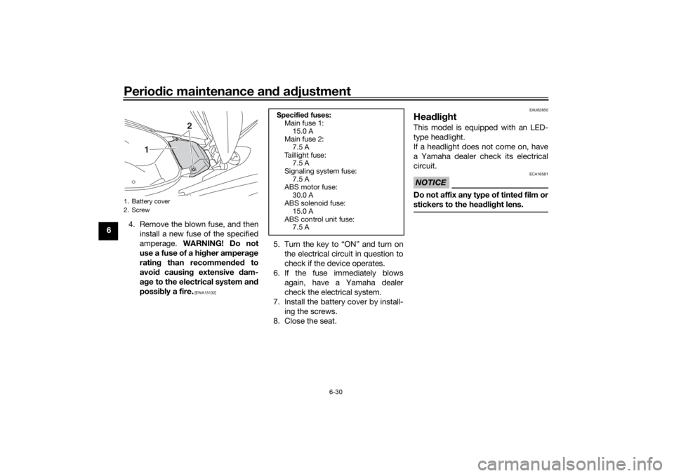
If a fuse is blown, replace it as follows.1. Turn the key to “OFF” and turn off the electrical circuit in question.
2. Open the seat. (See page 3-15.)
3. Remove the battery cover by re- moving the screws.1. Fuse box
1
1. Main fuse 1
2. ABS solenoid fuse
3. Main fuse 2
4. Taillight fuse
5. Signaling system fuse
6. ABS control unit fuse
7. ABS motor fuse
8. Spare fuse
1
2
3
4
5
67
8
U2DSE0E0.book Page 29 Thursday, March 19, 2015 10:34 AM
Page 70 of 90
Periodic maintenance an d a djustment
6-30
6 4. Remove the blown fuse, and then
install a new fuse of the specified
amperage. WARNING! Do not
use a fuse of a hi gher ampera ge
ratin g than recommen ded to
avoi d causin g extensive d am-
a g e to the electrical system an d
possi bly a fire.
[EWA15132]
5. Turn the key to “ON” and turn on
the electrical circuit in question to
check if the device operates.
6. If the fuse immediately blows again, have a Yamaha dealer
check the electrical system.
7. Install the battery cover by install- ing the screws.
8. Close the seat.
EAU62850
Hea dlig htThis model is equipped with an LED-
type headlight.
If a headlight does not come on, have
a Yamaha dealer check its electrical
circuit.NOTICE
ECA16581
Do not affix any type of tinte d film or
stickers to the hea dlig ht lens.
1. Battery cover
2. Screw
1
2
Specifie d fuses:
Main fuse 1:
15.0 A
Main fuse 2:
7.5 A
Taillight fuse: 7.5 A
Signaling system fuse: 7.5 A
ABS motor fuse:
30.0 A
ABS solenoid fuse: 15.0 A
ABS control unit fuse: 7.5 A
U2DSE0E0.book Page 30 Thursday, March 19, 2015 10:34 AM